EP0339275A2 - Procédé et dispositif pour l'adhésion sous pression d'un film mince à un substrat - Google Patents
Procédé et dispositif pour l'adhésion sous pression d'un film mince à un substrat Download PDFInfo
- Publication number
- EP0339275A2 EP0339275A2 EP89105433A EP89105433A EP0339275A2 EP 0339275 A2 EP0339275 A2 EP 0339275A2 EP 89105433 A EP89105433 A EP 89105433A EP 89105433 A EP89105433 A EP 89105433A EP 0339275 A2 EP0339275 A2 EP 0339275A2
- Authority
- EP
- European Patent Office
- Prior art keywords
- base plate
- film
- thin film
- carrier
- pressure
- Prior art date
- Legal status (The legal status is an assumption and is not a legal conclusion. Google has not performed a legal analysis and makes no representation as to the accuracy of the status listed.)
- Granted
Links
Images


Classifications
-
- B—PERFORMING OPERATIONS; TRANSPORTING
- B32—LAYERED PRODUCTS
- B32B—LAYERED PRODUCTS, i.e. PRODUCTS BUILT-UP OF STRATA OF FLAT OR NON-FLAT, e.g. CELLULAR OR HONEYCOMB, FORM
- B32B38/00—Ancillary operations in connection with laminating processes
- B32B38/0036—Heat treatment
-
- B—PERFORMING OPERATIONS; TRANSPORTING
- B29—WORKING OF PLASTICS; WORKING OF SUBSTANCES IN A PLASTIC STATE IN GENERAL
- B29C—SHAPING OR JOINING OF PLASTICS; SHAPING OF MATERIAL IN A PLASTIC STATE, NOT OTHERWISE PROVIDED FOR; AFTER-TREATMENT OF THE SHAPED PRODUCTS, e.g. REPAIRING
- B29C43/00—Compression moulding, i.e. applying external pressure to flow the moulding material; Apparatus therefor
- B29C43/32—Component parts, details or accessories; Auxiliary operations
- B29C43/56—Compression moulding under special conditions, e.g. vacuum
-
- B—PERFORMING OPERATIONS; TRANSPORTING
- B29—WORKING OF PLASTICS; WORKING OF SUBSTANCES IN A PLASTIC STATE IN GENERAL
- B29C—SHAPING OR JOINING OF PLASTICS; SHAPING OF MATERIAL IN A PLASTIC STATE, NOT OTHERWISE PROVIDED FOR; AFTER-TREATMENT OF THE SHAPED PRODUCTS, e.g. REPAIRING
- B29C63/00—Lining or sheathing, i.e. applying preformed layers or sheathings of plastics; Apparatus therefor
- B29C63/0091—Lining or sheathing, i.e. applying preformed layers or sheathings of plastics; Apparatus therefor in particular atmospheres
-
- B—PERFORMING OPERATIONS; TRANSPORTING
- B29—WORKING OF PLASTICS; WORKING OF SUBSTANCES IN A PLASTIC STATE IN GENERAL
- B29C—SHAPING OR JOINING OF PLASTICS; SHAPING OF MATERIAL IN A PLASTIC STATE, NOT OTHERWISE PROVIDED FOR; AFTER-TREATMENT OF THE SHAPED PRODUCTS, e.g. REPAIRING
- B29C63/00—Lining or sheathing, i.e. applying preformed layers or sheathings of plastics; Apparatus therefor
- B29C63/02—Lining or sheathing, i.e. applying preformed layers or sheathings of plastics; Apparatus therefor using sheet or web-like material
-
- B—PERFORMING OPERATIONS; TRANSPORTING
- B32—LAYERED PRODUCTS
- B32B—LAYERED PRODUCTS, i.e. PRODUCTS BUILT-UP OF STRATA OF FLAT OR NON-FLAT, e.g. CELLULAR OR HONEYCOMB, FORM
- B32B27/00—Layered products comprising a layer of synthetic resin
- B32B27/06—Layered products comprising a layer of synthetic resin as the main or only constituent of a layer, which is next to another layer of the same or of a different material
- B32B27/08—Layered products comprising a layer of synthetic resin as the main or only constituent of a layer, which is next to another layer of the same or of a different material of synthetic resin
-
- B—PERFORMING OPERATIONS; TRANSPORTING
- B32—LAYERED PRODUCTS
- B32B—LAYERED PRODUCTS, i.e. PRODUCTS BUILT-UP OF STRATA OF FLAT OR NON-FLAT, e.g. CELLULAR OR HONEYCOMB, FORM
- B32B3/00—Layered products comprising a layer with external or internal discontinuities or unevennesses, or a layer of non-planar shape; Layered products comprising a layer having particular features of form
- B32B3/02—Layered products comprising a layer with external or internal discontinuities or unevennesses, or a layer of non-planar shape; Layered products comprising a layer having particular features of form characterised by features of form at particular places, e.g. in edge regions
- B32B3/04—Layered products comprising a layer with external or internal discontinuities or unevennesses, or a layer of non-planar shape; Layered products comprising a layer having particular features of form characterised by features of form at particular places, e.g. in edge regions characterised by at least one layer folded at the edge, e.g. over another layer ; characterised by at least one layer enveloping or enclosing a material
-
- B—PERFORMING OPERATIONS; TRANSPORTING
- B32—LAYERED PRODUCTS
- B32B—LAYERED PRODUCTS, i.e. PRODUCTS BUILT-UP OF STRATA OF FLAT OR NON-FLAT, e.g. CELLULAR OR HONEYCOMB, FORM
- B32B37/00—Methods or apparatus for laminating, e.g. by curing or by ultrasonic bonding
- B32B37/10—Methods or apparatus for laminating, e.g. by curing or by ultrasonic bonding characterised by the pressing technique, e.g. using action of vacuum or fluid pressure
- B32B37/1018—Methods or apparatus for laminating, e.g. by curing or by ultrasonic bonding characterised by the pressing technique, e.g. using action of vacuum or fluid pressure using only vacuum
-
- B—PERFORMING OPERATIONS; TRANSPORTING
- B32—LAYERED PRODUCTS
- B32B—LAYERED PRODUCTS, i.e. PRODUCTS BUILT-UP OF STRATA OF FLAT OR NON-FLAT, e.g. CELLULAR OR HONEYCOMB, FORM
- B32B37/00—Methods or apparatus for laminating, e.g. by curing or by ultrasonic bonding
- B32B37/14—Methods or apparatus for laminating, e.g. by curing or by ultrasonic bonding characterised by the properties of the layers
- B32B37/16—Methods or apparatus for laminating, e.g. by curing or by ultrasonic bonding characterised by the properties of the layers with all layers existing as coherent layers before laminating
- B32B37/22—Methods or apparatus for laminating, e.g. by curing or by ultrasonic bonding characterised by the properties of the layers with all layers existing as coherent layers before laminating involving the assembly of both discrete and continuous layers
- B32B37/223—One or more of the layers being plastic
- B32B37/226—Laminating sheets, panels or inserts between two continuous plastic layers
-
- B—PERFORMING OPERATIONS; TRANSPORTING
- B32—LAYERED PRODUCTS
- B32B—LAYERED PRODUCTS, i.e. PRODUCTS BUILT-UP OF STRATA OF FLAT OR NON-FLAT, e.g. CELLULAR OR HONEYCOMB, FORM
- B32B38/00—Ancillary operations in connection with laminating processes
- B32B38/18—Handling of layers or the laminate
-
- G—PHYSICS
- G03—PHOTOGRAPHY; CINEMATOGRAPHY; ANALOGOUS TECHNIQUES USING WAVES OTHER THAN OPTICAL WAVES; ELECTROGRAPHY; HOLOGRAPHY
- G03F—PHOTOMECHANICAL PRODUCTION OF TEXTURED OR PATTERNED SURFACES, e.g. FOR PRINTING, FOR PROCESSING OF SEMICONDUCTOR DEVICES; MATERIALS THEREFOR; ORIGINALS THEREFOR; APPARATUS SPECIALLY ADAPTED THEREFOR
- G03F7/00—Photomechanical, e.g. photolithographic, production of textured or patterned surfaces, e.g. printing surfaces; Materials therefor, e.g. comprising photoresists; Apparatus specially adapted therefor
- G03F7/16—Coating processes; Apparatus therefor
- G03F7/161—Coating processes; Apparatus therefor using a previously coated surface, e.g. by stamping or by transfer lamination
-
- B—PERFORMING OPERATIONS; TRANSPORTING
- B29—WORKING OF PLASTICS; WORKING OF SUBSTANCES IN A PLASTIC STATE IN GENERAL
- B29C—SHAPING OR JOINING OF PLASTICS; SHAPING OF MATERIAL IN A PLASTIC STATE, NOT OTHERWISE PROVIDED FOR; AFTER-TREATMENT OF THE SHAPED PRODUCTS, e.g. REPAIRING
- B29C43/00—Compression moulding, i.e. applying external pressure to flow the moulding material; Apparatus therefor
- B29C43/32—Component parts, details or accessories; Auxiliary operations
- B29C43/56—Compression moulding under special conditions, e.g. vacuum
- B29C2043/561—Compression moulding under special conditions, e.g. vacuum under vacuum conditions
-
- B—PERFORMING OPERATIONS; TRANSPORTING
- B29—WORKING OF PLASTICS; WORKING OF SUBSTANCES IN A PLASTIC STATE IN GENERAL
- B29C—SHAPING OR JOINING OF PLASTICS; SHAPING OF MATERIAL IN A PLASTIC STATE, NOT OTHERWISE PROVIDED FOR; AFTER-TREATMENT OF THE SHAPED PRODUCTS, e.g. REPAIRING
- B29C43/00—Compression moulding, i.e. applying external pressure to flow the moulding material; Apparatus therefor
- B29C43/32—Component parts, details or accessories; Auxiliary operations
-
- B—PERFORMING OPERATIONS; TRANSPORTING
- B29—WORKING OF PLASTICS; WORKING OF SUBSTANCES IN A PLASTIC STATE IN GENERAL
- B29L—INDEXING SCHEME ASSOCIATED WITH SUBCLASS B29C, RELATING TO PARTICULAR ARTICLES
- B29L2031/00—Other particular articles
- B29L2031/34—Electrical apparatus, e.g. sparking plugs or parts thereof
- B29L2031/3425—Printed circuits
-
- B—PERFORMING OPERATIONS; TRANSPORTING
- B32—LAYERED PRODUCTS
- B32B—LAYERED PRODUCTS, i.e. PRODUCTS BUILT-UP OF STRATA OF FLAT OR NON-FLAT, e.g. CELLULAR OR HONEYCOMB, FORM
- B32B2309/00—Parameters for the laminating or treatment process; Apparatus details
- B32B2309/60—In a particular environment
- B32B2309/68—Vacuum
-
- B—PERFORMING OPERATIONS; TRANSPORTING
- B32—LAYERED PRODUCTS
- B32B—LAYERED PRODUCTS, i.e. PRODUCTS BUILT-UP OF STRATA OF FLAT OR NON-FLAT, e.g. CELLULAR OR HONEYCOMB, FORM
- B32B2457/00—Electrical equipment
- B32B2457/08—PCBs, i.e. printed circuit boards
-
- Y—GENERAL TAGGING OF NEW TECHNOLOGICAL DEVELOPMENTS; GENERAL TAGGING OF CROSS-SECTIONAL TECHNOLOGIES SPANNING OVER SEVERAL SECTIONS OF THE IPC; TECHNICAL SUBJECTS COVERED BY FORMER USPC CROSS-REFERENCE ART COLLECTIONS [XRACs] AND DIGESTS
- Y10—TECHNICAL SUBJECTS COVERED BY FORMER USPC
- Y10T—TECHNICAL SUBJECTS COVERED BY FORMER US CLASSIFICATION
- Y10T156/00—Adhesive bonding and miscellaneous chemical manufacture
- Y10T156/10—Methods of surface bonding and/or assembly therefor
- Y10T156/1052—Methods of surface bonding and/or assembly therefor with cutting, punching, tearing or severing
- Y10T156/108—Flash, trim or excess removal
-
- Y—GENERAL TAGGING OF NEW TECHNOLOGICAL DEVELOPMENTS; GENERAL TAGGING OF CROSS-SECTIONAL TECHNOLOGIES SPANNING OVER SEVERAL SECTIONS OF THE IPC; TECHNICAL SUBJECTS COVERED BY FORMER USPC CROSS-REFERENCE ART COLLECTIONS [XRACs] AND DIGESTS
- Y10—TECHNICAL SUBJECTS COVERED BY FORMER USPC
- Y10T—TECHNICAL SUBJECTS COVERED BY FORMER US CLASSIFICATION
- Y10T156/00—Adhesive bonding and miscellaneous chemical manufacture
- Y10T156/10—Methods of surface bonding and/or assembly therefor
- Y10T156/1089—Methods of surface bonding and/or assembly therefor of discrete laminae to single face of additional lamina
- Y10T156/1092—All laminae planar and face to face
- Y10T156/1093—All laminae planar and face to face with covering of discrete laminae with additional lamina
- Y10T156/1095—Opposed laminae are running length webs
-
- Y—GENERAL TAGGING OF NEW TECHNOLOGICAL DEVELOPMENTS; GENERAL TAGGING OF CROSS-SECTIONAL TECHNOLOGIES SPANNING OVER SEVERAL SECTIONS OF THE IPC; TECHNICAL SUBJECTS COVERED BY FORMER USPC CROSS-REFERENCE ART COLLECTIONS [XRACs] AND DIGESTS
- Y10—TECHNICAL SUBJECTS COVERED BY FORMER USPC
- Y10T—TECHNICAL SUBJECTS COVERED BY FORMER US CLASSIFICATION
- Y10T156/00—Adhesive bonding and miscellaneous chemical manufacture
- Y10T156/17—Surface bonding means and/or assemblymeans with work feeding or handling means
- Y10T156/1702—For plural parts or plural areas of single part
- Y10T156/1712—Indefinite or running length work
- Y10T156/1734—Means bringing articles into association with web
Definitions
- the present invention relates to the art of adhering a thin film to a base plate, and particularly relates to the art in which a dry film consisting of a light-transmissible resin film and a photosensitive resin layer provided on one side of the resin film is stuck under pressure to a base plate such as a printed circuit board and an electronic circuit substrate of silicon, gallium arsenide or the like without leaving an air bubble between the dry film and the base plate and without wrinkling the dry film.
- a base plate such as a printed circuit board and an electronic circuit substrate of silicon, gallium arsenide or the like
- the end of the base plate and that of the dry film are stuck to each other in the air at atmospheric pressure and the film and the plate are thereafter completely stuck to each other in a vacuum.
- the dry film consisting of a light-transmissible resin film and a photosensitive resin layer bonded to one side of the film is thus stuck to the base plate, under prescribed pressure and at a prescribed temperature in each of the conventional apparatuses.
- the photosensitive resin layer is thereafter exposed to light through a pattern mask overlaid on the light-transmissible resin film.
- the resin film is then removed.
- the resin layer is then etched so that a desired pattern is made on the base plate.
- an air bubble is likely to be left between the dry film and the base plate at the time the film and the plate are stuck to each other.
- the air bubble causes defects in the step of exposing the film and layer to light or the step of etching the resin layer, thereby causing problems for the process. If the dry film is entirely or partly stuck to the base plate in air at atmospheric pressure, not only will air bubbles likely be left between the dry film and the base plate but also the film will likely be wrinkled by the pressure of the rotating pressure sticking roller. This is another problem.
- the present invention was made in order to solve the above-mentioned problems.
- a pressure sticking means for sticking a conveyed thin film to a base plate, under pressure, in the environment of a vacuum or reduced pressure so as to form a stratified body.
- a significant feature of the thin film sticking method is that the thin film and the base plate are held at a prescribed distance from each other in the middle portion of a vacuum chamber in which the environment of a vacuum or reduced pressure can be generated.
- the thin film is placed between an upper contact member and a lower contact member.
- the upper contact member is made of an elastic material and provided in the upper portion of the vacuum chamber and is shaped such that its central portion is thicker than its peripheral portion thereof.
- the lower contact member is made of a material of higher rigidity than those of the base plate and the upper contact member, is vertically movably supported in the lower portion of the vacuum chamber and has a flat shape.
- the vacuum chamber is degassed so that a vacuum or reduced pressure is generated therein.
- the lower contact member is moved up in that environment to push up the base plate placed in the middle of the vacuum chamber.
- the lower contact member is moved up further to push the thin film into pressure contact with the upper contact member by the top of the base plate to stick the thin film and the base plate to each other under pressure at a prescribed temperature.
- the thin film and the base plate are thereafter further stuck to each other in the air at atmospheric pressure by a heat and pressure roller.
- a thin film sticking, apparatus includes a pressure sticking means by which a conveyed thin film is stuck to a base plate under pressure in a vacuum or at reduced pressure so as to form a stratified body.
- the apparatus comprises an upper contact member which is shaped semicylindrically or hemispherically to have a larger thickness in the central portion thereof than in the peripheral portion with the convex surface thereof projecting downward and is attached to the bottom of an elastic support member in a vacuum chamber in which a vacuum or reduced pressure can be generated.
- a lower contact member which is made of a material of greater hardness than the upper contact member and has a flat shape can be moved up and down.
- Means are provided for holding the thin film and the base plate at a prescribed distance from each other between the upper and the lower contact members. Means are also provided for degassing the vacuum chamber to generate a vacuum or reduced pressure therein. Further means are provided for moving up the lower contact member to pinch the thin film between the upper and lower contact members by a prescribed force to stick the thin film and the base plate to each other under pressure. A heat and pressure sticking roller is also provided for sticking the thin film and the base plate to each other under pressure further in the air at atmospheric pressure.
- the thin film and the base plate are stuck to each other under pressure in a vacuum or at reduced pressure in the vacuum chamber such that the area of the pressure sticking is gradually increased from the central portion of the base plate to the peripheral portion thereof the film and the plate are stuck to each other under pressure without leaving air bubbles between the film and the plate and without wrinkling the film.
- FIG 1 is a schematic view illustrating a dry film sticking method and a dry film sticking apparatus in accordance with preferred embodiments of the invention.
- the apparatus includes a loader 2 by which base plates 1 are transferred one after another onto a carrier 3 from a cassette 1a put on a vertically movable support arm 2a.
- a cassette sensor 2a ⁇ provided on the top 2a′ of the support arm as shown in Figure 3B detects the cassette.
- the sensor 2a ⁇ is of the optical fiber type or the pressure detection type.
- the support arm 2a is moved up and down by a vertical mover 2b while being guided by a guide column 2c attached to a stand 2k, as shown in Figures 2A and 2B.
- the vertical mover 2b is made of a screw unit.
- the vertical drive motor 2b′ of the vertical mover 2b is put into action.
- a light blocking member 2d provided on the support arm 2a reaches a position 3c′ such that the light blocking member blocks light from a position light sensor 2e attached to the stand 2k, the motor 2b′ is stopped.
- the position 3c′ is predetermined so that after the lowermost base plate 1, whose bottom is on the same plane as a carrying surface 3c, is transferred out of the cassette 1a onto the carrying surface, the height from the position 3c′ to the second lowermost base plate 1 housed in the cassette 1a so as to be transferred next is detected by the cassette sensor 2a ⁇ and the vertical drive motor 2b′ is then put into action to move down the second lowermost base plate to the position 3c′. Even if the base plates 1 are not housed in all the housing sections of the cassette 1a, each base plate to be transferred next can be brought to the prescribed position 3c′ through the action of the cassette sensor 2a ⁇ .
- a push-out cylinder 2f for pushing the base plate 1 onto carrying surface 3c is attached to the stand 2k at the same height as the position 3c′ .
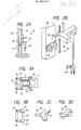
- Figure 3A shows a plan view of the push-out cylinder 2f.
- Figure3B shows a plan view of the support arm 2a and the cassette sensor 2a ⁇ .
- Figure 3C shows a perspective view of the base plate push-out rod 2g of the push-out cylinder 2f.
- Figure 3D shows a perspective view of a modification 2g′ of the base plate push-out rod of the push-out cylinder 2f.
- Shown at 3b in Figure 3A is a transfer roller attached to the support frame of a conveyer.
- the carrier 3, on which the base plate 1 is placed is supported by the rotatable roller 3b to change the direction of movement of the carrier.
- a pusher 2h for pushing the base plate 1 is provided, and a tongue 2i is attached to the bottom of the pusher to support the base plate 1 at the bottom thereof when the base plate is transferred from the cassette 1a onto the carrier 3.
- a pusher 2h′ is provided, and tongues 2i′ are attached to the bottom of the pusher to support the base plate 1 at the bottom thereof when the base plate is transferred from the cassette 1a onto the carrier 3.
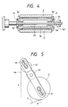
- the vertically wound carrier support portion 3a′ of a carrier feed means 3a for supplying the vertically wound carrier 3′ is provided with a conventional brake mechanism 3a ⁇ composed of a friction plate 31 and a spring 32 to apply to a tensile force to the carrier 3, as shown in Figure 4.
- the carrier feed means 3a includes a rotary shaft 33 and a carrier winding cylinder 34.
- the transfer roller 3b shown in Figure 1 acts to change the direction of travel of the carrier 3 to move it horizontally, and also supports the base plate 1 at the time of the transfer thereof.
- a loosening roller unit 3d including upper and lower rollers 3e and 3f is provided as shown in Figure 1.
- a pressure cylinder 3e′ is provided over the upper roller 3e to pinch the carrier 3 to apply a tensile force thereto between the roller unit 3d and the carrier feed means 3a.
- a loosening motor 3f′ is rotated by such a quantity as to loosen the carrier 3 downstream of the loosening roller unit 3d.
- the vertically wound dry film support portion of a dry film feed means 4a is provided with the same kind of brake mechanism as that for the vertically wound carrier feed means 3a.
- the peripheral surface of a cover film winding roller 4f for winding a cover film 4e is in contact with that of an idle roller 4h, which is in contact with that of a vertically wound dry film 4′, so that the cover film 4e is wound on the cover film winding roller by the same length as the dry film 4 unwound from the vertically wound dry film 4′.
- Contact pressure keepers 4j and 4k are provided to keep the contact pressure between the rollers 4f and 4h and the wound film 4′ at a prescribed level.
- the idle roller 4h may be eliminated.
- the peripheral surface of the cover film winding roller 4f and that of the vertically wound dry film 4′ are located in contact with each other, and the direction of rotation of the roller 4f is made reverse to that in the case that the idle roller is provided.
- a vacuum chamber 5 is defined by an upper box 5f secured to a base 5e, and a lower box 5g which is vertically movably supported by a vertical mover 53 made of a pneumatic cylinder.
- the lower box 5g is provided with a sealing means 5c in contact with the upper box 5f.
- the sealing means 5c is made of an 0-ring 5c′ for keeping the vacuum chamber 5 airtight at the convey-in port 5a and convey-out port 5b thereof.
- a pressure sensor 5h is provided in the vacuum chamber 5.
- the chamber 5 is provided with an air extraction port 5i.
- a heater 5j for setting a temperature for the pressure sticking of the dry film 4 and the base plate 1 may be provided in the vacuum chamber 5.
- the size of the convey-in port 5a of the vacuum chamber 5 is such that the distance between the top 51 of the port and the dry film 4 is ⁇ , that between the bottom 52 of the port and the carrier 3 is ⁇ , and that between the distances ⁇ and ⁇ is ⁇ which enables the dry film and the carrier to pass through the port, as shown in Figure 6.
- the thickness ⁇ of the base plate 1 on the carrier 3 is smaller than the distance ⁇ . For example.
- a lower contact member 6b is vertically movably supported by a vertical mover 54 made of a pneumatic cylinder.
- the top of the lower contact member 6b is such a smooth surface that the carrier 3 is not damaged when the conveyed-in carrier is moved while the bottom thereof is in slip contact with the top of the lower contact member.
- An upper contact member 6a, whose bottom is convex downward is provided.
- a conventional heat and pressure sticking roller 7b is provided adjacent the vacuum chamber outlet.
- a pneumatic cylinder 7b′ is provided over the roller 7b to apply a prescribed downward pushing force thereto.
- the upper holding member 10c of the upstream holder 10b of a cutoff means 10 is vertically movably supported by a pneumatic cylinder 10c′.
- the lower holding member 10d of the upstream holder 10b is secured to a base 10′.
- the upper and lower holding members 10e′ and 10e ⁇ of the downstream holder 10e of the cutoff means 10 are usually in mutually opened positions at such a distance from each other that the members do not interfere with the stratified body holding member 9a of a film pull-out means 9.
- the upper and the lower holding members 10e′ and 10e ⁇ are vertically closed to each other by an upper and a lower pneumatic cylinders 10f and 10f′.
- a rotary cutter 10a shown in Figure 7 is moved from one side edge of the stratified body 20 to the other side edge thereof by a timing belt 10g while the body is held by the upper and the lower holding members 10e′ and 10e ⁇ and the cutter is rotated through engagement with a rack 10 ⁇ attached to the base 10′, so that the dry film 4 of the body is cut off.
- the cutoff means 10 includes a suction unit 10h for removing air from the space surrounded by the upstream and the downstream holders 10b and 10e, so that a chip made from the stratified body 20 in cutting off the dry film 4 thereof is prevented from flying away.
- the stratified body 20 having the dry film 4 cut off by the cutter 10a is held by the holding member 9a of the film pull-out means 9 which is moved by a timing belt 9b so that the stratified body is conveyed out to an unloader 11 and put into a cassette 11b through an outlet chute 11a.
- the tension of the dry film 4 is maintained between a tension roller 4c and the upstream holder 10b.
- the stratified body 20 is held by the holding member 9a instead of the upstream holder and the dry film 4 is pulled out from the vertically wound dry film 4′ by the movement of the film pull-out means so that the tension of the film 4 is maintained.
- the dry film sticking method will now be described in detail with reference to the drawings.
- the support arm 2a of a loader 2 is moved up and down by a vertical mover 2b while being guided on a guide column 2c.
- a base plate 1 is thereby moved to the same height as the carrying surface 3c of a carrier 3
- a light blocking member 2d is detected by a position light sensor 2e to stop the vertical movement of the support arm 2a, and the lowermost base plate 1 is transferred from a cassette 1a onto the carrying surface 3c of the carrier 3.
- a push-out rod 2g consists of a pusher 2h and a tongue 2i so that the base plate 1, which would become unstable due to the displacement of the center of gravity thereof in being transferred from the cassette 1a onto the carrier 3, is supported by the tongue and thereby securely transferred from the cassette onto the carrier.
- a carrier feed means 3a is provided under the carrying surface 3c.
- the carrier 3 is moved into a vacuum chamber 5 along a loosening roller unit 3d including a transfer roller 3b for receiving the base plate 1 and changing the direction of travel of the carrier to move it horizontally, and a pair of rollers 3e and 3f for loosening the carrier.
- a dry film feed means 4a is provided over the carrying surface 3c so that a dry film 4 coated with a cover film 4e is unwound from large roller 4′ and moved in between a turn roller 4b and a cover roller 4d.
- the cover film 4e is peeled from the dry film 4, turned upward and taken up by a cover film winding roller 4f.
- the dry film 4 is moved into the vacuum chamber 5 while receiving a prescribed tensile force between a tension roller 4c and a film pull-out means 9.
- the height of the bottom of an upper contact member 6a is set to be equal to that of the top 51 of the inlet port 5a of the vacuum chamber 5.
- the height of the top of a lower contact member 6b is set to be such that the loose carrier 3 carrying the base plate 1 does not come into contact with the bottom 52 of the inlet port 5a. As a result, the base plate 1 is conveyed while the bottom of the carrier 3 slips on the smooth top of the lower contact member 6b.
- the dry film 4 and the carrier 3 are moved by the movement of the film pull-out means 9.
- the movement of the dry film 4 and the carrier 3 is stopped and a pair of sealing means 5c provided at the inlet port 5a and outlet port 5b are moved up to push the carrier and the dry film onto the edges at the tops 51 of the inlet and the outlet ports to seal the vacuum chamber 5.
- the air is then extracted from the vacuum chamber 5.
- the lower contact member 6b is moved up by an actuator 54 so that the dry film 4, the base plate 1 and the carrier 3 are stuck to each other under pressure, between the lower contact member and the upper contact member 6a.
- Figure 8A shows that the base plate 1 is stopped at the central portion of the lower contact member 6b.
- Figure 8B shows that the vacuum chamber 5 is sealed by pushing the sealing means 5c onto the dry film 4 and the carrier 3 at the tops 51 of the convey-in and the convey-out ports 5a and 5b. Since the carrier 3 is loose although the air is extracted from the sealed vacuum chamber 5, the top of the base plate 1 and the dry film 4 do not come into contact with each other.
- Figure 8C shows that the lower contact member 6b is moved up to push the dry film 4, the base plate 1 and the carrier 3 onto the upper contact member 6a by a prescribed lifting force to stick the film, the plate and the carrier to each other under pressure as the upper contact member is elastically deformed.
- the lower photosensitive resin layer of the dry film 4 begins to come into contact with the central portion of the base plate 1 first and then gradually comes into contact with the peripheral portion thereof as well, along with the elevation of the lower contact member 6b toward the upper contact member in the pressure sticking of the dry film and the base plate. Since the dry film 4 and the base plate 1 are thus stuck to each other under pressure in the vacuum chamber at reduced pressure, starting with the central portion of the base plate, no air bubbles will be left between the photosensitive resin layer of the dry film 4 and the base plate at the time of completion of the pressure sticking thereof and the dry film will not be wrinkled as a result of the pressure sticking.
- the dry film 4 the base plate 1 and the carrier 3 are thus stuck to each other by a pressure sticking means 6 comprising the upper contact member 6a, the lower contact member 6b and an actuator 6c so that the dry film, the base plate and the carrier form a stratified body 20 as shown in Figure 9.
- a pressure sticking means 6 comprising the upper contact member 6a, the lower contact member 6b and an actuator 6c so that the dry film, the base plate and the carrier form a stratified body 20 as shown in Figure 9.
- a vertical mover 53 which acts as a sealing control means, is moved down
- the stratified body 20 is moved onto a stage 7a so that the stratified body is subjected to secondary pressure sticking by the downward pressure of a heat and a pressure sticking roller 7b.
- the pressure rolling step may be avoided.
- the heating step during the step of compression in the vacuum chamber may be eliminated.
- rollers 3e and 3f, tension roller 4c and pull out means 9 maintain film 3 relatively loose and carrier film 4 relatively tense. This insures separation of the base plate and the thin film when they enter the vacuum chamber. Also, when the vacuum chamber is sealed the seals will pinch the thin film 4 and carrier 3 thereby continuing to maintain the base plate and thin film separate from one another while the chamber is degassed. In this way the vacuum or reduced pressure will exist before the thin film first touches the base plate, insuring a better sticking of the thin film to the base plate.
- the movement of the stratified body is stopped and the body is held at the cutting station thereof by upstream and downstream holders 10b and 10e.
- the cutter 10a is then moved to cut off the stratified body 20 at the prescribed portion thereof.
- the body is conveyed downstream further by the film pull-out means 9. The body 20 is then released from the film pull-out means 9 and put into a cassette.
- a thin film and a base plate are stuck to each other under pressure in a vacuum chamber so that the area of the pressure sticking is gradually increased from the central portion of the base plate to the peripheral portion thereof. For that reason, the thin film and the base plate are stuck to each other under pressure without leaving an air bubble between the thin film and the base plate and without wrinkling the thin film.
Landscapes
- Engineering & Computer Science (AREA)
- Physics & Mathematics (AREA)
- Manufacturing & Machinery (AREA)
- Fluid Mechanics (AREA)
- General Physics & Mathematics (AREA)
- Mechanical Engineering (AREA)
- Thermal Sciences (AREA)
- Lining Or Joining Of Plastics Or The Like (AREA)
- Manufacturing Of Printed Circuit Boards (AREA)
- Laminated Bodies (AREA)
Applications Claiming Priority (4)
| Application Number | Priority Date | Filing Date | Title |
|---|---|---|---|
| JP63072960A JPH0622200B2 (ja) | 1988-03-25 | 1988-03-25 | 薄膜張付方法及びその実施装置 |
| JP63072959A JPH0622199B2 (ja) | 1988-03-25 | 1988-03-25 | 薄膜圧着方法及び薄膜圧着装置 |
| JP72959/88 | 1988-03-25 | ||
| JP72960/88 | 1988-03-25 |
Publications (3)
| Publication Number | Publication Date |
|---|---|
| EP0339275A2 true EP0339275A2 (fr) | 1989-11-02 |
| EP0339275A3 EP0339275A3 (en) | 1990-10-10 |
| EP0339275B1 EP0339275B1 (fr) | 1996-05-01 |
Family
ID=26414091
Family Applications (1)
| Application Number | Title | Priority Date | Filing Date |
|---|---|---|---|
| EP89105433A Expired - Lifetime EP0339275B1 (fr) | 1988-03-25 | 1989-03-28 | Procédé et dispositif pour l'adhésion sous pression d'un film mince à un substrat |
Country Status (3)
| Country | Link |
|---|---|
| US (1) | US5078820A (fr) |
| EP (1) | EP0339275B1 (fr) |
| DE (1) | DE68926361T2 (fr) |
Cited By (15)
| Publication number | Priority date | Publication date | Assignee | Title |
|---|---|---|---|---|
| EP0324596A3 (fr) * | 1988-01-11 | 1991-04-10 | Morton International, Inc. | Méthode et appareil pour l'application de matériaux polymères aux circuits imprimés |
| DE4106460A1 (de) * | 1990-05-22 | 1991-11-28 | Somar Corp | Klebevorrichtung |
| EP0460621A1 (fr) * | 1990-06-04 | 1991-12-11 | Hakuto Co., Ltd. | Dispositif de laminage à vide |
| EP0422542A3 (en) * | 1989-10-10 | 1992-01-02 | Manville Corporation | Apparatus and method for encapsulating contoured articles |
| EP0528566A1 (fr) | 1991-08-09 | 1993-02-24 | Morton International, Inc. | Dispositif de laminage à vide avec convoyeur, et procédé d'utilisation de l'appareil |
| EP0501358B1 (fr) * | 1991-02-25 | 1997-01-15 | Canon Kabushiki Kaisha | Méthode et dispositif de connexion pour composants électriques |
| WO1999048673A1 (fr) * | 1998-03-20 | 1999-09-30 | Cww-Gerko Akustik Gmbh & Co. Kg | Dispositif pour appliquer une pellicule, notamment une pellicule a effet acoustique |
| EP1072390A1 (fr) * | 1999-07-29 | 2001-01-31 | Hitachi Techno Engineering Co., Ltd. | Dispositif pour appliquer un film sous vide |
| GB2355958A (en) * | 1999-11-02 | 2001-05-09 | Richard Warrington George | Forming plastics sheets or forming and bonding plastics sheets onto a substrate |
| FR2809583A1 (fr) * | 2000-05-26 | 2001-11-30 | Siemens Ag | Procede de stratification d'une plaquette de circuit imprime sur une plaquette de base et dispositif de stratification |
| US6942751B1 (en) | 1999-11-02 | 2005-09-13 | Permacoat Limited | Method and apparatus for thermoforming of plastic sheets |
| EP2189284A2 (fr) | 2008-11-21 | 2010-05-26 | komax Holding AG | Dispositif de laminage d'un module solaire |
| EP3363617A1 (fr) * | 2017-02-16 | 2018-08-22 | 3M Innovative Properties Company | Appareil pour l'application d'un film |
| CN108715026A (zh) * | 2018-05-23 | 2018-10-30 | 何红侠 | 一种铝合金生产加工用整平贴膜装置 |
| CN111823695A (zh) * | 2020-08-04 | 2020-10-27 | 颜军 | 一种强力上胶复合贴合设备 |
Families Citing this family (33)
| Publication number | Priority date | Publication date | Assignee | Title |
|---|---|---|---|---|
| JP2899825B2 (ja) * | 1990-08-24 | 1999-06-02 | 株式会社新川 | リードフレーム押え装置 |
| JPH0753357B2 (ja) * | 1990-12-20 | 1995-06-07 | ソマール株式会社 | 薄膜切り抜き方法とその実施装置 |
| US5679610A (en) * | 1994-12-15 | 1997-10-21 | Kabushiki Kaisha Toshiba | Method of planarizing a semiconductor workpiece surface |
| JPH09141743A (ja) * | 1995-11-24 | 1997-06-03 | N P C:Kk | ラミネート装置 |
| US5587043A (en) * | 1995-06-05 | 1996-12-24 | Brady Usa, Inc. | Thin label applicator |
| US5967030A (en) * | 1995-11-17 | 1999-10-19 | Micron Technology, Inc. | Global planarization method and apparatus |
| US5972780A (en) * | 1996-08-22 | 1999-10-26 | Nippon Telegraph Telephone Corporation | Thin film forming apparatus and method |
| US5788802A (en) * | 1996-10-22 | 1998-08-04 | Preco Industries, Inc. | Vacuum drum feed and alignment apparatus for multiple layer laminator |
| US7640836B1 (en) | 1997-03-28 | 2010-01-05 | Preco Industries, Inc. | Method for simultaneous x, y and θ registration of segment of continuous web with a processing station |
| WO1998043788A1 (fr) * | 1997-03-28 | 1998-10-08 | Preco Industries, Inc. | Appareil alimente en feuille ou bande et comprenant un mecanisme de positionnement grande vitesse |
| US6316363B1 (en) | 1999-09-02 | 2001-11-13 | Micron Technology, Inc. | Deadhesion method and mechanism for wafer processing |
| US6331488B1 (en) * | 1997-05-23 | 2001-12-18 | Micron Technology, Inc. | Planarization process for semiconductor substrates |
| US6218316B1 (en) | 1998-10-22 | 2001-04-17 | Micron Technology, Inc. | Planarization of non-planar surfaces in device fabrication |
| US6050318A (en) * | 1998-12-11 | 2000-04-18 | Record Products Of America, Inc. | Apparatus and method for protective layer application |
| US6518172B1 (en) * | 2000-08-29 | 2003-02-11 | Micron Technology, Inc. | Method for applying uniform pressurized film across wafer |
| US6499526B1 (en) * | 2000-10-11 | 2002-12-31 | The United States Of America As Represented By The Secretary Of The Navy | Umbilical cable bonding tool |
| JP3883929B2 (ja) * | 2001-09-25 | 2007-02-21 | 大日本スクリーン製造株式会社 | 薄膜形成装置および薄膜形成方法 |
| WO2007085043A1 (fr) * | 2006-01-24 | 2007-08-02 | Mycrolab Pty Ltd | Procédés de fabrication bon marché de matériaux et dispositifs stratifiés complexes |
| JP4666519B2 (ja) * | 2006-09-08 | 2011-04-06 | リンテック株式会社 | シート貼付装置 |
| CN101262744B (zh) * | 2007-03-08 | 2011-01-19 | 奈电软性科技电子(珠海)有限公司 | 假贴机 |
| DE102007027999A1 (de) | 2007-06-14 | 2008-12-18 | Leonhard Kurz Gmbh & Co. Kg | Heißprägen von Strukturen |
| DE102007027998A1 (de) * | 2007-06-14 | 2008-12-18 | Leonhard Kurz Gmbh & Co. Kg | Heißprägen von Leiterbahnen auf Photovoltaik-Silizium-Wafer |
| JP4773419B2 (ja) * | 2007-12-20 | 2011-09-14 | リンテック株式会社 | シート貼付装置及び貼付方法 |
| JP5334135B2 (ja) | 2010-08-20 | 2013-11-06 | ニチゴー・モートン株式会社 | 積層装置 |
| TWI402171B (zh) * | 2010-11-11 | 2013-07-21 | C Sun Mfg Ltd | 壓合裝置及其壓合方法 |
| JP6136936B2 (ja) * | 2012-02-01 | 2017-05-31 | 旭硝子株式会社 | 積層体の製造方法および製造装置 |
| US20130312907A1 (en) * | 2012-05-23 | 2013-11-28 | Lg Display Co., Ltd. | Substrate-bonding apparatus for display device and method for manufacturing bonded substrate |
| CN103144398B (zh) * | 2013-03-06 | 2015-04-22 | 旭东机械(昆山)有限公司 | 贴膜机及其贴膜方法 |
| CN105538902B (zh) * | 2015-12-30 | 2018-05-18 | 浙江新嘉联电子科技有限公司 | 一种自动震膜装配机的盖膜组件 |
| CN107214971A (zh) * | 2017-05-08 | 2017-09-29 | 安徽颍瑞源焊管科技有限公司 | 一种集成墙面板压平覆膜装置 |
| JP7355809B2 (ja) * | 2018-07-30 | 2023-10-03 | コーニング インコーポレイテッド | 流体の流れを用いた基板梱包装置及び方法 |
| DE102018215939A1 (de) * | 2018-09-19 | 2020-03-19 | Profol GmbH | Werkzeug zum Aufbringen einer Folie |
| CN110789768B (zh) * | 2019-11-29 | 2021-09-28 | 航天科技控股集团股份有限公司 | 一种车载终端产品自动贴膜方法 |
Family Cites Families (24)
| Publication number | Priority date | Publication date | Assignee | Title |
|---|---|---|---|---|
| US1206656A (en) * | 1912-08-01 | 1916-11-28 | Edouard Benedictus | Press-plate. |
| NL302012A (fr) * | 1963-08-14 | |||
| US3322598A (en) * | 1963-10-02 | 1967-05-30 | Alvin M Marks | Laminator for securing continuous flexible film to a base |
| US3860473A (en) * | 1969-07-03 | 1975-01-14 | Glen L Wesen | Method for making pressure sensitive label records |
| US3658629A (en) * | 1970-02-27 | 1972-04-25 | Ibm | Photopolymer resist sheet laminator |
| US4544619A (en) * | 1970-03-03 | 1985-10-01 | Shipley Company Inc. | Photosensitive laminate |
| US3870582A (en) * | 1972-10-05 | 1975-03-11 | Polaroid Corp | Novel laminating system |
| US4152188A (en) * | 1973-05-25 | 1979-05-01 | Saint-Gobain Industries | Method and apparatus for manufacture of laminated glazing |
| DE2544553C2 (de) * | 1974-10-08 | 1983-08-04 | E.I. du Pont de Nemours and Co., 19898 Wilmington, Del. | Verfahren zum Aufbringen einer photopolymerisierbaren festen Resistschicht auf ein Substrat |
| US4127436A (en) * | 1975-04-17 | 1978-11-28 | E. I. Du Pont De Nemours And Company | Vacuum laminating process |
| FR2447819A1 (fr) * | 1979-01-30 | 1980-08-29 | Essilor Int | Procede et dispositif pour la decoration d'un quelconque substrat, en particulier monture de lunettes |
| DE2932845C2 (de) * | 1979-08-14 | 1981-04-09 | G. Siempelkamp Gmbh & Co, 4150 Krefeld | Vorrichtung zum Zusammenlegen von Pressgutpaketen bei der Herstellung von Laminatplatten |
| US4316757A (en) * | 1980-03-03 | 1982-02-23 | Monsanto Company | Method and apparatus for wax mounting of thin wafers for polishing |
| US4373846A (en) * | 1980-10-24 | 1983-02-15 | Charbonnet Carl D | Panel transferring apparatus |
| US4338152A (en) * | 1981-02-17 | 1982-07-06 | E. I. Du Pont De Nemours And Company | Gripping arrangement for an apparatus for automatically laminating circuit boards |
| FR2530186A1 (fr) * | 1982-07-19 | 1984-01-20 | Saint Gobain Vitrage | Procede pour recouvrir d'une pellicule de protection en matiere plastique une ebauche de verre de lunettes et dispositif pour la realisation de ce procede |
| FR2546635B1 (fr) * | 1983-05-25 | 1986-07-04 | Saint Gobain Vitrage | Procede et dispositif pour recouvrir une ebauche d'un verre de lunettes par une feuille de protection |
| US4511425A (en) * | 1983-06-13 | 1985-04-16 | Dennison Manufacturing Company | Heated pad decorator |
| FR2561169B1 (fr) * | 1984-03-14 | 1987-02-27 | Perus Rene | Procede et dispositif de fabrication de verre feuillete de securite |
| CA1243417A (fr) * | 1984-03-16 | 1988-10-18 | Shoji Tanaka | Dispositif de lamellage de cartes a circuit imprime |
| JPS6252552A (ja) * | 1985-08-30 | 1987-03-07 | Hitachi Chem Co Ltd | 減圧貼り合わせ方法及び装置 |
| JPS62117389A (ja) * | 1985-11-15 | 1987-05-28 | 日立化成工業株式会社 | フレキシブル配線板の製造法 |
| JPH01289132A (ja) * | 1988-01-11 | 1989-11-21 | Morton Thiokol Inc | 印刷配線に重合体材料を貼着する方法および装置 |
| US4834821A (en) * | 1988-01-11 | 1989-05-30 | Morton Thiokol, Inc. | Process for preparing polymeric materials for application to printed circuits |
-
1989
- 1989-03-24 US US07/328,402 patent/US5078820A/en not_active Expired - Fee Related
- 1989-03-28 EP EP89105433A patent/EP0339275B1/fr not_active Expired - Lifetime
- 1989-03-28 DE DE68926361T patent/DE68926361T2/de not_active Expired - Fee Related
Cited By (25)
| Publication number | Priority date | Publication date | Assignee | Title |
|---|---|---|---|---|
| EP0324596A3 (fr) * | 1988-01-11 | 1991-04-10 | Morton International, Inc. | Méthode et appareil pour l'application de matériaux polymères aux circuits imprimés |
| EP0422542A3 (en) * | 1989-10-10 | 1992-01-02 | Manville Corporation | Apparatus and method for encapsulating contoured articles |
| DE4106460A1 (de) * | 1990-05-22 | 1991-11-28 | Somar Corp | Klebevorrichtung |
| EP0460621A1 (fr) * | 1990-06-04 | 1991-12-11 | Hakuto Co., Ltd. | Dispositif de laminage à vide |
| EP0501358B1 (fr) * | 1991-02-25 | 1997-01-15 | Canon Kabushiki Kaisha | Méthode et dispositif de connexion pour composants électriques |
| US6015081A (en) * | 1991-02-25 | 2000-01-18 | Canon Kabushiki Kaisha | Electrical connections using deforming compression |
| US5292388A (en) * | 1991-08-09 | 1994-03-08 | Morton International, Inc. | Conveyorized vacuum applicator and method therefor |
| EP0528566A1 (fr) | 1991-08-09 | 1993-02-24 | Morton International, Inc. | Dispositif de laminage à vide avec convoyeur, et procédé d'utilisation de l'appareil |
| WO1999048673A1 (fr) * | 1998-03-20 | 1999-09-30 | Cww-Gerko Akustik Gmbh & Co. Kg | Dispositif pour appliquer une pellicule, notamment une pellicule a effet acoustique |
| US6199613B1 (en) | 1998-03-20 | 2001-03-13 | Cww-Gerko Akustik Gmbh & Co. Kg | Apparatus for applying padding, especially acoustically active padding |
| EP1072390A1 (fr) * | 1999-07-29 | 2001-01-31 | Hitachi Techno Engineering Co., Ltd. | Dispositif pour appliquer un film sous vide |
| US6453963B1 (en) | 1999-07-29 | 2002-09-24 | Hitachi Techno Engineering Co., Ltd. | Vacuum film laminating apparatus |
| US6942751B1 (en) | 1999-11-02 | 2005-09-13 | Permacoat Limited | Method and apparatus for thermoforming of plastic sheets |
| GB2355958A (en) * | 1999-11-02 | 2001-05-09 | Richard Warrington George | Forming plastics sheets or forming and bonding plastics sheets onto a substrate |
| GB2355958B (en) * | 1999-11-02 | 2004-02-11 | Richard Warrington George | A method of and apparatus for forming plastics sheets |
| FR2809583A1 (fr) * | 2000-05-26 | 2001-11-30 | Siemens Ag | Procede de stratification d'une plaquette de circuit imprime sur une plaquette de base et dispositif de stratification |
| EP2189284A2 (fr) | 2008-11-21 | 2010-05-26 | komax Holding AG | Dispositif de laminage d'un module solaire |
| EP2189283A1 (fr) * | 2008-11-21 | 2010-05-26 | komax Holding AG | Appareil de lamination d'un module de cellule solaire |
| US8191599B2 (en) | 2008-11-21 | 2012-06-05 | Komax Holding Ag | Apparatus for laminating a solar module |
| EP3363617A1 (fr) * | 2017-02-16 | 2018-08-22 | 3M Innovative Properties Company | Appareil pour l'application d'un film |
| WO2018150323A1 (fr) * | 2017-02-16 | 2018-08-23 | 3M Innovative Properties Company | Appareil pour appliquer un film |
| CN108715026A (zh) * | 2018-05-23 | 2018-10-30 | 何红侠 | 一种铝合金生产加工用整平贴膜装置 |
| CN108715026B (zh) * | 2018-05-23 | 2020-06-19 | 湖北精洲铝业有限公司 | 一种铝合金生产加工用整平贴膜装置 |
| CN111823695A (zh) * | 2020-08-04 | 2020-10-27 | 颜军 | 一种强力上胶复合贴合设备 |
| CN111823695B (zh) * | 2020-08-04 | 2022-06-07 | 郴州科宝新材料科技有限公司 | 一种强力上胶复合贴合设备 |
Also Published As
| Publication number | Publication date |
|---|---|
| DE68926361D1 (de) | 1996-06-05 |
| EP0339275B1 (fr) | 1996-05-01 |
| US5078820A (en) | 1992-01-07 |
| DE68926361T2 (de) | 1996-11-28 |
| EP0339275A3 (en) | 1990-10-10 |
Similar Documents
| Publication | Publication Date | Title |
|---|---|---|
| US5078820A (en) | Method and apparatus for pressure sticking a thin film to a base plate | |
| US5641372A (en) | Transferring apparatus and transferring method | |
| EP0318806B1 (fr) | Procédé pour enlever une bande protectrice d'une plaquette | |
| CA1079175A (fr) | Appareil et methode d'empaquetage a vide | |
| KR20190027007A (ko) | 필름을 기판에 라미네이팅하는 장치 및 그 방법 | |
| WO2018149378A1 (fr) | Appareil et procédé de transfert de matériau d'emballage en plastique | |
| CN207497009U (zh) | 一种3d曲面玻璃贴膜机 | |
| US4984017A (en) | Vacuum contact type printing machine and method of contact therefor | |
| JP2835475B2 (ja) | 真空包装袋整形装置 | |
| JPH0622200B2 (ja) | 薄膜張付方法及びその実施装置 | |
| JPH05262319A (ja) | 目的物を包装する装置及び方法 | |
| JP2014017309A (ja) | フィルム状樹脂積層装置 | |
| EP0337578B1 (fr) | Procédé et dispositif de production de cartes postales illustrées | |
| JP2009212430A (ja) | ウエハ取り出し装置及び半導体装置の製造方法 | |
| GB2237262A (en) | Manufacturing labels on a continuous web | |
| TW202209421A (zh) | 薄膜材貼附裝置及薄膜材貼附方法 | |
| CN113471085A (zh) | 器件密封方法、器件密封装置和半导体产品的制造方法 | |
| TWI874602B (zh) | 元件密封方法、元件密封裝置及半導體製品的製造方法 | |
| TW202147506A (zh) | 黏著片貼附方法、黏著片貼附裝置及半導體製品的製造方法 | |
| TWI883179B (zh) | 黏著片貼附方法、黏著片貼附裝置及半導體製品的製造方法 | |
| US5815548A (en) | Photographing device and X-ray photographing system utilizing the same | |
| TWI874601B (zh) | 元件密封方法、元件密封裝置及半導體製品的製造方法 | |
| JP4156733B2 (ja) | 貼付装置 | |
| TWI892862B (zh) | 壓膜方法 | |
| TW202131425A (zh) | 面板自動處理裝置和面板自動處理方法 |
Legal Events
| Date | Code | Title | Description |
|---|---|---|---|
| PUAI | Public reference made under article 153(3) epc to a published international application that has entered the european phase |
Free format text: ORIGINAL CODE: 0009012 |
|
| AK | Designated contracting states |
Kind code of ref document: A2 Designated state(s): DE FR GB |
|
| PUAL | Search report despatched |
Free format text: ORIGINAL CODE: 0009013 |
|
| AK | Designated contracting states |
Kind code of ref document: A3 Designated state(s): DE FR GB |
|
| 17P | Request for examination filed |
Effective date: 19901224 |
|
| 17Q | First examination report despatched |
Effective date: 19930714 |
|
| GRAH | Despatch of communication of intention to grant a patent |
Free format text: ORIGINAL CODE: EPIDOS IGRA |
|
| GRAA | (expected) grant |
Free format text: ORIGINAL CODE: 0009210 |
|
| AK | Designated contracting states |
Kind code of ref document: B1 Designated state(s): DE FR GB |
|
| PG25 | Lapsed in a contracting state [announced via postgrant information from national office to epo] |
Ref country code: FR Effective date: 19960501 |
|
| REF | Corresponds to: |
Ref document number: 68926361 Country of ref document: DE Date of ref document: 19960605 |
|
| EN | Fr: translation not filed | ||
| PLBE | No opposition filed within time limit |
Free format text: ORIGINAL CODE: 0009261 |
|
| STAA | Information on the status of an ep patent application or granted ep patent |
Free format text: STATUS: NO OPPOSITION FILED WITHIN TIME LIMIT |
|
| 26N | No opposition filed | ||
| PGFP | Annual fee paid to national office [announced via postgrant information from national office to epo] |
Ref country code: GB Payment date: 20000322 Year of fee payment: 12 |
|
| PGFP | Annual fee paid to national office [announced via postgrant information from national office to epo] |
Ref country code: DE Payment date: 20000327 Year of fee payment: 12 |
|
| PG25 | Lapsed in a contracting state [announced via postgrant information from national office to epo] |
Ref country code: GB Free format text: LAPSE BECAUSE OF NON-PAYMENT OF DUE FEES Effective date: 20010328 |
|
| GBPC | Gb: european patent ceased through non-payment of renewal fee |
Effective date: 20010328 |
|
| PG25 | Lapsed in a contracting state [announced via postgrant information from national office to epo] |
Ref country code: DE Free format text: LAPSE BECAUSE OF NON-PAYMENT OF DUE FEES Effective date: 20020101 |