EP0339439A2 - Outil de sciage - Google Patents
Outil de sciage Download PDFInfo
- Publication number
- EP0339439A2 EP0339439A2 EP89106955A EP89106955A EP0339439A2 EP 0339439 A2 EP0339439 A2 EP 0339439A2 EP 89106955 A EP89106955 A EP 89106955A EP 89106955 A EP89106955 A EP 89106955A EP 0339439 A2 EP0339439 A2 EP 0339439A2
- Authority
- EP
- European Patent Office
- Prior art keywords
- saw
- cutting
- plastic
- band
- hard
- Prior art date
- Legal status (The legal status is an assumption and is not a legal conclusion. Google has not performed a legal analysis and makes no representation as to the accuracy of the status listed.)
- Withdrawn
Links
Images

Classifications
-
- B—PERFORMING OPERATIONS; TRANSPORTING
- B23—MACHINE TOOLS; METAL-WORKING NOT OTHERWISE PROVIDED FOR
- B23D—PLANING; SLOTTING; SHEARING; BROACHING; SAWING; FILING; SCRAPING; LIKE OPERATIONS FOR WORKING METAL BY REMOVING MATERIAL, NOT OTHERWISE PROVIDED FOR
- B23D61/00—Tools for sawing machines or sawing devices; Clamping devices for these tools
- B23D61/18—Sawing tools of special type, e.g. wire saw strands, saw blades or saw wire equipped with diamonds or other abrasive particles in selected individual positions
- B23D61/185—Saw wires; Saw cables; Twisted saw strips
Definitions
- the invention relates to a sawing tool according to the preamble of claim 1.
- the subsidiary claim 3 represents an alternative application of the inventive idea.
- saw ropes or bandsaw blades are used as rotating sawing tools on a band saw machine.
- These sawing tools preferably have diamond-coated cutting or grinding elements which enable processing in rock-like materials such as marble or the like.
- these cutting or grinding elements are designed, for example, as cutting sleeves or so-called cutting beads, which are pulled onto the wire rope and crimped onto the wire rope at intervals.
- the space between the cutting beads can be filled with a plastic coating made of a hard, wear-resistant plastic or by pulling on metal springs.
- the cutting beads are fixed in their axial position, these can optionally also be fastened in a rotating manner on the wire rope.
- the ends of the wire rope are fastened to form an endless rope for a band saw machine.
- the lock is opened and the rope is passed through a hole in the workpiece.
- the cutting elements are, for example, soldered onto the carrier material consisting of spring band steel or fastened thereto by means of a riveted connection, screw connection or the like.
- Separate holders for the cutting elements can also be provided, the holder being connected to the carrier material.
- Both saw cable and saw band are subject to constant alternating bending stress during operation. It has been shown in particular in the case of saw ropes that the various material components do not always guarantee optimum durability or stability of the sawing tool. If you pull the cutting beads onto the wire rope and surround the spaces between the cutting beads with a hard, wear-resistant plastic layer, the rope becomes hard and not very flexible overall, which leads to a non-circular running and to a premature breakage of the strands. In addition, the hard plastic coating largely prevents the cutting beads from rotating freely, since the plastic partly flows into the space between the rope strand and the plastic sleeve.
- the plastic coating is chosen so strong that the outer diameter of the plastic coating corresponds approximately to the outer diameter of the cutting pearl, by none Form paragraphs in the sawing tool.
- the thickness of the plastic layer is thus determined by the thickness of the cutting pearl or cutting sleeve.
- the cutting sleeve cannot be made as thin as desired. This results in a relatively thick plastic layer made of hard, wear-resistant plastic, which, however, makes the sawing tool inflexible and lacks the suppleness of the stranded base material of the saw cable. Furthermore, the saw cable breaks prematurely.
- the cutting elements are applied to the base material of the saw band and coated with a plastic layer to fill in the gaps between the cutting elements to avoid disruptive heels.
- This plastic layer must also be hard and wear-resistant or low-wear in order to allow for a low removal of the plastic when processing in rock-like materials. This leads to the same poor flexibility and flexibility of the saw band as described for the saw cable.
- the invention has for its object to avoid the disadvantages described above.
- a sawing tool is to be created which ensures a high degree of stability with optimum flexibility.
- the sawing tool according to the invention is based on the knowledge that the durability of the sawing cable or the saw band can be increased if the basic material, ie. H. the wire rope for the saw rope or the spring band steel for a saw band, is provided with a first plastic coating made of soft, flexible plastic in order to give the base material a protective layer.
- This protective layer initially ensures constant flexibility of the base material and prevents the metal sleeve of the cutting element from coming into direct contact with the metal wire rope. This prevents wear between these parts.
- the inner, flexible plastic coating serves as a kind of padding, so that the second, hard and low-wear plastic coating above no longer has to be applied in the usual thickness or thickness. Since the outer, hard plastic coating wears essentially to the same extent as the cutting beads, ie to a small extent, it is not necessary that this hard plastic layer be chosen to be very thick in the wall thickness. However, if you can make this second, hard outer plastic layer thinner, the flexibility of the sawing tool remains largely what also leads to a lower tendency of the wire rope to break overall.
- This part of the sawing tool is therefore provided with a protective layer by the first plastic layer completely covering the rope or the saw band, which, however, gives the flexibility of the base material, ie. H. wire rope or spring steel, not affected. This avoids direct contact with metal - metal through the cutting sleeves to be applied or through intermediate springs between the cutting sleeves or cutting beads.
- the outer plastic coating can be adapted in the outer diameter to the outer diameter of the cutting beads or the outer dimensions of the cutting elements in the case of the saw band, so that a sawing tool results without shoulders, which is expedient for a smooth, smooth operation in operation.
- the cutting elements are initially also surrounded with a very thin layer of the plastic coating in order to obtain transport protection or protection against injury before use. In use, the plastic layer on the cutting elements and the rest of the corresponding area of the plastic coating are then immediately ground off.
- the thickness of the outer hard plastic layer is largely determined by how strong the wear on the cutting beads or the cutting elements themselves is. It therefore only needs to be the same or slightly larger than the expected removal on the cutting elements.
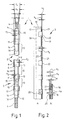
- the sawing tool 1 shown in FIGS. 1 and 2 is designed in FIG. 1 as a sawing rope 2, in FIG. 2 as a saw band 3, for use as an endlessly rotating sawing tool on a band sawing machine, not shown in detail.
- the saw cable 2 shown in Fig. 1 consists of a stranded wire rope 4, at the ends of which a fastener 5 consisting of two parts is attached.
- the closure 5 is used to open the endless rope so that internal cuts can be made in a workpiece.
- the two closure parts 6, 7 are joined together via a form-fitting anti-rotation device 8 (tongue and groove) and joined together by means of a union nut 9 surrounding the two parts 6, 7.
- the stranded wire rope 4 is covered with a first plastic coating 10 over its entire surface.
- the cutting elements 11 drawn onto the wire rope 4 with a plastic coating 10 are designed as cylindrical cutting sleeves or as so-called cutting beads. They are not squeezed onto the base body, so that they can rotate freely on this first plastic coating 10.
- the cutting pearls 11 have a known diamond coating 12 on their outer surface, which serves as a cutting layer or grinding layer for removal during workpiece machining.
- the closure 5 is also provided with a diamond coating 12 so that it also acts like a cutting element.
- the space 13 between two cutting elements 11 or between the cutting element adjacent to the closure 5 and the closure itself is filled with a second, hard and low-wear plastic layer 14 as a plastic coating to fix the position of the cutting elements.
- This second plastic coating 14 is used on the one hand to fix the position of the cutting elements 11 and on the other hand to produce a saw rope that is as free as possible, which is important for a smooth and uniform running of the saw rope.
- the outer diameter d3 of the second plastic layer 14 is therefore chosen to be the same or only slightly smaller than the outer diameter d4 of the cutting element 11.
- the wall thickness s2 of the outer plastic layer 14 is chosen at least so large that it corresponds to the amount of the cutting element 11 to be expected to be removed. d. H. the amount of the wall thickness s3 of the diamond coating 12 corresponds. In Fig. 1 the wall thickness s2 of the plastic layer 14 is shown larger for better visibility.
- the wall thickness of the second plastic layer is denoted by s2, the wall thickness of the diamond coating 12 by s3. Accordingly, it applies s2 ⁇ s3. However, since the diamond coating 12 is usually very thin, the wall thickness s2 of the second plastic layer 14 will be greater than the wall thickness s3 of the diamond coating, ie s2 ⁇ s3.
- the wall thickness s2 of the second plastic layer 14 should only be made so strong that it acts as a wear layer when removing the diamond coating 12. At the same time, it should have a sufficient supporting force for fixing the position of the cutting elements 11.
- the remaining space between the inner diameter d2 of the second plastic layer 14 and the outer diameter d1 of the wire rope 4 is filled with the first plastic coating 10 with a wall thickness s1.
- the wall thickness s1 of the first plastic coating 10 is made smaller than the wall thickness s2 of the second plastic coating. This can also be the other way round.
- the first plastic coating 10 can be made even stronger in the intermediate areas 13 in the wall thickness s 1, in order to serve as a lining to achieve the overall diameter.
- the first plastic cover has the advantage that it is flexible and soft and thus ensures the flexibility of the saw cable. In the area of the cutting elements 11, however, the wall thickness of the first plastic layer 10 is limited by the necessary wall thickness of the cutting sleeve 11.
- the first plastic coating can therefore be designed step-shaped, wherein it can be formed s1 in the gaps 13 in the wall thickness.
- a metal spring or plastic spring 15 can also be inserted into the intermediate space 13. This is shown as an alternative in the lower area in FIG. 1.
- the inner first plastic layer 10 protects the wire rope 4 against premature wear due to the mutual contact of metal parts.
- the invention is shown with the aid of a saw band 3 for use on a band saw machine.
- the base material 16 which is generally made of spring steel, is initially wholly or partially provided with a soft, flexible plastic coating 17.
- the plastic coating 17 can completely or for example only partially coat the base material 16, for example up to the line 18.
- the cutting elements 19 with front diamond coating 20 are generally firmly soldered to the base material 16 or otherwise riveted or screwed, so that in this case the cutting elements can be attached before or after the plastic coating with the first plastic layer 17.
- a second plastic layer 21 made of a hard, wear-resistant material with a thickness s5 is applied to the first soft plastic layer 17 with a thickness s4.
- the two plastic layers 17, 21 together result in a thickness corresponding to the amount s6 by which the cutting element 19 protrudes beyond the front edge 22 of the base material 16, i. H. s4 + s5 ⁇ s6.
- the layer thickness s5 of the second, hard plastic layer 21 is chosen as possible so that it corresponds to the maximum expected removal of the diamond coating 20. However, it is shown thicker in FIG. 2.
- the plastic coating consisting of the first coating 17 and the second coating 21 is also matched to the overall width s7, ie the cutting elements 19 with the diamond coating 20 go into the as seamless as possible subsequent plastic layer over.
- the thicknesses s4 and s5 of the two plastic coatings 17, 21 shown in FIG. 2b may have different values than in FIG. 2a.
- the decisive factor is the seamless embedding of the cutting elements 19 on the saw band, the second, outer hard plastic layer being made only as thick as is absolutely necessary for the abrasion. Otherwise, the plastic layer is formed by the first, softer plastic layer 17.
- FIGS. 3 and 4 shows the use of a saw cable according to the illustration and description according to FIG. 1 on a circular saw blade 22 (FIG. 3) or a gang saw blade 23 (FIG. 4).
- the cutting elements 11 are applied to the circulating endless saw cable 2.
- recesses 44 are provided in the saw blade base material, so that the cutting elements or cutting beads are loosely embedded in this area and are therefore rotatable.
- the remaining rope area between the cutting elements is supported on the end face 25 of the circular saw blade 22.
- the end face 25 is provided with U-shaped recesses 26 in order to form a type of U-shaped bearing surface for the rope so that the rope does not jump off the carrier material.
- the embodiment of the invention according to FIG. 4 provides that the saw cable 2 according to FIG. 1 in a frame saw blade o.
- the like. Is arranged similarly, as described for Fig. 3.
- recesses 28 for receiving the cutting beads 11 are again contained in the carrier material 27.
- the cutting beads can optionally rotate freely in the recesses 28.
- the remaining rope area is in turn mounted in a U-shaped recess 29 in the end face 30 against slipping out laterally.
- the saw cable 2 itself is constructed as described for FIG. 1.
- the carrier material 27 can be used as a frame saw or as another band saw blade. In the case of a frame saw, however, the sawing rope would be tensioned linearly and not as an endless rope.
Landscapes
- Engineering & Computer Science (AREA)
- Mechanical Engineering (AREA)
- Processing Of Stones Or Stones Resemblance Materials (AREA)
- Sawing (AREA)
Applications Claiming Priority (2)
| Application Number | Priority Date | Filing Date | Title |
|---|---|---|---|
| DE3813850A DE3813850A1 (de) | 1988-04-23 | 1988-04-23 | Saegewerkzeug |
| DE3813850 | 1988-04-23 |
Publications (2)
| Publication Number | Publication Date |
|---|---|
| EP0339439A2 true EP0339439A2 (fr) | 1989-11-02 |
| EP0339439A3 EP0339439A3 (fr) | 1990-09-05 |
Family
ID=6352793
Family Applications (1)
| Application Number | Title | Priority Date | Filing Date |
|---|---|---|---|
| EP19890106955 Withdrawn EP0339439A3 (fr) | 1988-04-23 | 1989-04-19 | Outil de sciage |
Country Status (2)
| Country | Link |
|---|---|
| EP (1) | EP0339439A3 (fr) |
| DE (1) | DE3813850A1 (fr) |
Cited By (3)
| Publication number | Priority date | Publication date | Assignee | Title |
|---|---|---|---|---|
| EP0489356A1 (fr) * | 1990-12-03 | 1992-06-10 | Mvz Maschinenbau Und Verzahnungstechnik, Johannes Falkenstein | Scie à fil |
| WO1996001715A1 (fr) * | 1994-07-08 | 1996-01-25 | Houmaro Slijptechniek B.V. | Outil d'usinage |
| EP2535160A1 (fr) | 2011-06-17 | 2012-12-19 | NV Bekaert SA | Câble pour scie à fil |
Family Cites Families (17)
| Publication number | Priority date | Publication date | Assignee | Title |
|---|---|---|---|---|
| IT573635A (fr) * | ||||
| US2810189A (en) * | 1953-02-24 | 1957-10-22 | Lasalle Steel Co | Milling cutters |
| US2855669A (en) * | 1954-04-28 | 1958-10-14 | Nicolet Ind Inc | Coated cut-off saw for asbestos articles |
| US2793478A (en) * | 1954-05-24 | 1957-05-28 | Bjorksten Res Lab Inc | Cutting tool and method of making |
| DE1088408B (de) * | 1955-12-27 | 1960-09-01 | Wallram Hartmetall | Werkzeug zur Steinbearbeitung |
| FR1142604A (fr) * | 1956-02-09 | 1957-09-20 | Perfectionnements aux dispositifs de sciage pour la pierre et analogues | |
| US3598101A (en) * | 1968-10-01 | 1971-08-10 | Carborundum Co | Wire saw |
| DE1933230A1 (de) * | 1969-07-01 | 1971-01-21 | Theresia Tullius | Hochflexibles Band einer Steinsaegemaschine mit aufgeloeteten aufgeschweissten oder durch Fliesspressen befestigten,ein- oder beiderseitig in Hauptbewegungsrichtung messerartig zugespitzten,mit Hartstoffen,z.B. Diamant durchsetzten Scnneidkoerpern |
| US3741192A (en) * | 1972-01-21 | 1973-06-26 | Carborundum Co | Abrasive cable saw cutting member |
| SU517498A1 (ru) * | 1972-06-12 | 1976-08-12 | Научно-Исследовательский Институт Камня И Силикатов | Дискова пила |
| US3884212A (en) * | 1973-11-01 | 1975-05-20 | Meyers W F Co | Wire saw |
| SU963842A2 (ru) * | 1980-10-08 | 1982-10-07 | Ордена Трудового Красного Знамени Институт Сверхтвердых Материалов Ан Усср | Бесконечна алмазно-абразивна пила |
| DE3147287C2 (de) * | 1981-11-28 | 1984-07-05 | Messner, Caspar O.H., Prof.Dr.sc.techn., Zürich | Verfahren zum Herstellen eines Schneiddrahtes |
| SU1057298A1 (ru) * | 1982-07-22 | 1983-11-30 | Научно-Исследовательский Институт Камня И Силикатов | Канатна пила |
| DE3323409C1 (de) * | 1983-06-29 | 1985-03-28 | Festo-Maschinenfabrik Gottlieb Stoll, 7300 Esslingen | Sägeblatt |
| IT8453307V0 (it) * | 1984-04-27 | 1984-04-27 | Brocco Emilio E Oberto Tarena | Filo diamantato per il taglio dipietre e marmi |
| DE3507188A1 (de) * | 1985-03-01 | 1986-09-04 | Festo KG, 7300 Esslingen | Maschinell antreibbare saege zum durchtrennen von nichtmetallischen materialien wie kork, eternit, glasfaser, plexiglas o.dgl. |
-
1988
- 1988-04-23 DE DE3813850A patent/DE3813850A1/de not_active Withdrawn
-
1989
- 1989-04-19 EP EP19890106955 patent/EP0339439A3/fr not_active Withdrawn
Cited By (4)
| Publication number | Priority date | Publication date | Assignee | Title |
|---|---|---|---|---|
| EP0489356A1 (fr) * | 1990-12-03 | 1992-06-10 | Mvz Maschinenbau Und Verzahnungstechnik, Johannes Falkenstein | Scie à fil |
| WO1996001715A1 (fr) * | 1994-07-08 | 1996-01-25 | Houmaro Slijptechniek B.V. | Outil d'usinage |
| NL9401139A (nl) * | 1994-07-08 | 1996-02-01 | Houmaro Slijptechniek Bv | Werkwijze voor het vervaardigen van een zaag. |
| EP2535160A1 (fr) | 2011-06-17 | 2012-12-19 | NV Bekaert SA | Câble pour scie à fil |
Also Published As
| Publication number | Publication date |
|---|---|
| EP0339439A3 (fr) | 1990-09-05 |
| DE3813850A1 (de) | 1989-11-02 |
Similar Documents
| Publication | Publication Date | Title |
|---|---|---|
| DE2451153C2 (de) | Bandsäge | |
| DE3608193C2 (fr) | ||
| EP1745757B1 (fr) | Instrument pour canal radiculaire avec revêtement abrasif et son procédé de fabrication | |
| DE10109321B4 (de) | Dentalwerkzeug | |
| DE3888942T2 (de) | Bandsäge zum Schneiden von Nuten in Steine. | |
| DE10030168A1 (de) | Sägeblatt | |
| DE2106998B2 (de) | Schneidklinge zum Schneiden von Flachmaterial | |
| DE3114687A1 (de) | Schneidblatt | |
| DE2904841A1 (de) | Saegezahndraht fuer aufloesewalzen von offenend-spinnaggregaten | |
| EP0414280B1 (fr) | Dispositif de jonction pour scie à fil | |
| EP0339439A2 (fr) | Outil de sciage | |
| DE1460705A1 (de) | Schervorrichtung fuer Textilmaterial | |
| DE29720261U1 (de) | Fräszahn zur Erdbearbeitung | |
| DE60018136T2 (de) | Kettensägehalter und -schwertanordnung für eine Baumerntemaschine | |
| DE3101842C2 (fr) | ||
| DE3715290A1 (de) | Saegeblatt | |
| EP2390035A1 (fr) | Fil de sciage | |
| DE3109176C2 (de) | Schneideinsatz zum Schälen bzw. Wellendrehen | |
| DE8610809U1 (de) | Arbeitsschutzhandschuh | |
| EP0316389B1 (fr) | Scie à ruban | |
| DE2220062B2 (de) | Schleifstift | |
| DE69509303T2 (de) | Schleifwerkzeug in Schichtkonstruktion zum Bearbeiten von Plattenkanten aus Marmor, Granit und ähnlichem | |
| DE20009331U1 (de) | Bracket | |
| DE3805405A1 (de) | Saegewerkzeug | |
| WO2001019578A1 (fr) | Lame de scie et son procede de production |
Legal Events
| Date | Code | Title | Description |
|---|---|---|---|
| PUAI | Public reference made under article 153(3) epc to a published international application that has entered the european phase |
Free format text: ORIGINAL CODE: 0009012 |
|
| AK | Designated contracting states |
Kind code of ref document: A2 Designated state(s): AT BE CH DE FR GB IT LI LU NL SE |
|
| PUAL | Search report despatched |
Free format text: ORIGINAL CODE: 0009013 |
|
| AK | Designated contracting states |
Kind code of ref document: A3 Designated state(s): AT BE CH DE FR GB IT LI LU NL SE |
|
| 17P | Request for examination filed |
Effective date: 19910227 |
|
| 17Q | First examination report despatched |
Effective date: 19930121 |
|
| STAA | Information on the status of an ep patent application or granted ep patent |
Free format text: STATUS: THE APPLICATION IS DEEMED TO BE WITHDRAWN |
|
| 18D | Application deemed to be withdrawn |
Effective date: 19930602 |