EP0339574A2 - Système pour déglacer des rails - Google Patents
Système pour déglacer des rails Download PDFInfo
- Publication number
- EP0339574A2 EP0339574A2 EP89107472A EP89107472A EP0339574A2 EP 0339574 A2 EP0339574 A2 EP 0339574A2 EP 89107472 A EP89107472 A EP 89107472A EP 89107472 A EP89107472 A EP 89107472A EP 0339574 A2 EP0339574 A2 EP 0339574A2
- Authority
- EP
- European Patent Office
- Prior art keywords
- rail
- trough
- cable
- heating cable
- carrier member
- Prior art date
- Legal status (The legal status is an assumption and is not a legal conclusion. Google has not performed a legal analysis and makes no representation as to the accuracy of the status listed.)
- Withdrawn
Links
Images



Classifications
-
- E—FIXED CONSTRUCTIONS
- E01—CONSTRUCTION OF ROADS, RAILWAYS, OR BRIDGES
- E01B—PERMANENT WAY; PERMANENT-WAY TOOLS; MACHINES FOR MAKING RAILWAYS OF ALL KINDS
- E01B19/00—Protection of permanent way against development of dust or against the effect of wind, sun, frost, or corrosion; Means to reduce development of noise
-
- Y—GENERAL TAGGING OF NEW TECHNOLOGICAL DEVELOPMENTS; GENERAL TAGGING OF CROSS-SECTIONAL TECHNOLOGIES SPANNING OVER SEVERAL SECTIONS OF THE IPC; TECHNICAL SUBJECTS COVERED BY FORMER USPC CROSS-REFERENCE ART COLLECTIONS [XRACs] AND DIGESTS
- Y02—TECHNOLOGIES OR APPLICATIONS FOR MITIGATION OR ADAPTATION AGAINST CLIMATE CHANGE
- Y02A—TECHNOLOGIES FOR ADAPTATION TO CLIMATE CHANGE
- Y02A30/00—Adapting or protecting infrastructure or their operation
- Y02A30/30—Adapting or protecting infrastructure or their operation in transportation, e.g. on roads, waterways or railways
Definitions
- the present disclosure is an improved system for reducing ice accumulation on rails.
- the most common means of reducing the accumulation of ice on rails is to apply heat to the rails by the attachment of an electric heating cable to the rails.
- a common means of securing a heating cable to a rail has employed the use of adhesive. Effective attachment of a heater cable to a rail by adhesive is very difficult. This method requires that the portion of the rail to receive the attachment of the heating cable be cleaned thoroughly such as with a wire brush and then wiped with a solvent. Thereafter the adhesive must be applied within a relatively few hours before oxidation of the metal re-occurs. The installation of a heating cable by adhesive is particularly sensitive to high humidity and to low temperatures. For these reasons, attaching a heating cable to a rail by adhesive has proven to be expensive and unreliable.
- Another method which has been used employs spring-type clips which are attached to the base portion of the rail and which have an integral portion extending from the base portion up along one side of the rail web portion.
- the resiliency of the spring-type clip is used to hold an electric heating cable in position against the underneath surface of the rail top portion.
- These spring-type clips have also not proven to be reliable.
- the tension available from such spring-type clip to force contact of the heating cable with the rail is usually insufficient to accomplish effective heat transfer.
- the present disclosure overcomes the limitations of the existing attachment systems by providing a much more effective, dependable and economical system for holding an electric cable in contact with a rail.
- the system employs the use of retention means or members such as threaded studs. These threaded studs are attached to one side of the rail web portion such as by means of spot welding, drilling and tapping or explosive driving.
- the employment of studs is important in that they provide a strong, permanent and dependable base element for supporting other elements necessary to retain the electric heating cable in contact with the rail.
- One embodiment of the system of this invention includes the use of a series of elongated carrier members each defined in cross-section normal to the length thereof by an upper trough-forming portion and a lower clamping portion.
- the clamping portion has openings spaced along the length thereof in register with and arranged to receive studs extending from the rail.
- a heating cable is then positioned within the carrier member's trough portions. Thereafter, a locking means, such as a nut and most preferably a nut and washer, are used on the studs to retain the trough-forming portion and thereby the heating cable therein in close proximity to the rail top portion.
- a locking means such as a nut and most preferably a nut and washer, are used on the studs to retain the trough-forming portion and thereby the heating cable therein in close proximity to the rail top portion.
- One embodiment employs the use of a series of elongated trough members adaptable for fitting in end-to-end relationship.
- the heating cable is received within the trough members.
- Brackets are employed at spaced intervals to hold the trough members in position.
- Each bracket is supported by a threaded stud affixed to the rail web portion.
- a nut is in use to retain each of the brackets securely in position on a stud to force the trough members and thereby the heating cable therein in contact with the rail upper portion.
- a heating cable can be expeditiously secured in contact with a rail and placed in optimal position for transferring heat to the rail upper portion.
- the system can be installed by unskilled labor and the attachment system is substantially immune to failure. Further, the system is adaptable to easy replacement of the cable if necessary.
- a rail generally indicated by the numeral 10 is shown in elevational cross-sectional view, the rail being characteristic of one type used for mass transit.
- the rail provides a surface for the wheel of the transit vehicle to pass thereover and in some instances simultaneously provides a source of electrical energy for supplying energy for the vehicle.
- the rail includes an upright web portion 12, a base portion 14 and a top portion 16.
- the top portion 16 has an upper surface 18 on which the wheels of the vehicle roll and on which ice and snow tend to accumulate.
- An objective of the present disclosure is to provide an improved system to heat the rail top portion 16 so as to reduce the accumulation of snow and ice on the top surface 18.
- Web portion 12 has opposed vertical surfaces 20 and 22. Affixed to surface 20 is a stud 24 and in like manner, affixed to surface 22 is a stud 26.
- the studs 24 and 26 can be affixed to web 12 in diferent ways. One means is by the use of welding, including spot welding so that the inner end of each of the studs 24 and 26 is welded to the corresponding web surfaces 20 and 22. Other means (not shown) includes drilling and tapping the web portion 12 so that the studs can be threaded into such tapped openings or the use of explosive driven studs.
- Carrier member 28 Secured to stud 24 is an elongated carrier member generally indicated by the numeral 28, the carrier member being shown in cross-section.
- Carrier member 28 is in the form of an extrusion and may be of a any length which is convenient to handle, such as 10 feet.
- the carrier member 28 includes two basic integral portions, that is, an upward trough portion 30 and a lower retention portion 32.
- Retention portion 32 may also be referred to as a clamping portion.
- the retention portion 32 has openings 34 spaced along the length thereof. Openings 34(only one of which is shown in the carrier member 28) may be spaced every two or three feet apart as an example and are spaced in register with studs 24 secured at the same intervals to the rail web portion 12.
- an electrically heated cable 38 Positioned in the carrier member top portion 30 is an electrically heated cable 38, which may be of the type generally used for industrial heating purposes and can be either a metal clad or plastic clad cable with resistive conductors therein. In some instances such heating cables are metal clad and are filled with mineral insulation.
- the particular type of heating cable is not relevant to this disclosure; however, providing an improved system of supporting the cable for effective transfer of heat from the cable to the rail top portion 16 is the essence of the invention.
- an insulation strip 40 Positioned within the trough portion 30 is an insulation strip 40 which may be in the form of an insulating tape having adhesive backing on one side.
- the insulating strip 40 can be formed as an elongated strip of insulation material such as made of polyurethane, polystyrene, PVC form or the like.
- the bottom surface of the insulating backing can have an adhesive thereon so that it will readily adhere to the interior of the carrier member trough portion 30.
- the interior surface of the insulating strip can be provided with a full cover.
- the carrier member 28 is held in position by means of a washer 42 and nut 44.
- the carrier member trough portion 30 securely holds heating cable 38 in direct contact with the lower surface 16A of the rail upper portion 16. This permits direct heat transfer from the heating cable 38 to the rail upper portion 16.
- the trough portion 30 provides a substantially closed space 36 along each side of the cable 38 which space is heated by the cable by an oven effect and this heat of convection is also transferred to the rail upper portion 16.
- the use of insulation strip 40 reduces the transfer of heat from the cable 38 to the carrier member 28 to thereby concentrate the heat in the rail upper portion 16 rather than into the carrier member 28.
- the carrier member 28 is shown in a downwardly tilted portion in dotted outline which is the normal position of the carrier member before nut 44 is tightened. It can be seen that in this attitude the trough portion 30 is open at the top. In this manner the cable 38 may be easily laid into the open trough along an extended length of rail. Thereafter, as the nut 44 on each stud 26 is tightened, the carrier member moves the cable up into contact with the rail's upper portion 16. This illustrates the ease of use of the system of this invention. Further, Figure 1 illustrates the ease by which cable 38 may be replaced if it develops an open circuit or for other reasons.
- a wind shield 48 is shown affixed to stud 24 and held in position by nut 50.
- the wind shield contacts the underneath surface 16A of the rail upper portion 16 and the top surface 14A of the rail base portion 14 and provides a closed space 52 between the shield and the rail web portion 12. This reduces air circulation and insures more efficient heat transfer from the heating cable 38 to the rail. While shown on only one side of the rail, typically they are placed on both sides of the rail when wind shields are used.
- Figure 3 shows an alternate embodiment of the invention in which the carrier member is of a different configuration.
- the carrier member generally indicated by the numeral 28A is of shorter elevation in cross-section, but still includes a retention portion 32A and a trough portion 30A.
- the function of the carrier member of the configuration shown in Figure 3 is the same as that shown with reference to Figures 1 and 2, however, the installation of the cable is different.
- the cable is first in position within the trough portion 30A of the carrier member and then the carrier member is inserted onto the spaced apart studs 24. Thereafter a washer 42 and a stud 44 is applied to stud 24 to retain cable 38 in contact with the rail.
- the cable 38 is held in contact in a favorable position, that is, at the juncture of the web inner surface 22 and the top portion lower surface 16A.
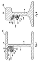
- Figure 4 shows an alternate embodiment of the arrangement of Figure 3 in which the rail is of a cross-sectional configuration more similar to that used for long distance rail systems in which the rail upper portion 16A is relatively thick and of less width compared to the web portion 12.
- the trough portion 30B of the carrier member 28B is configured somewhat differently as well as the retention portion 32B. Comparing Figures 1, 3 and 4 shows how the practice of the invention may employ carrier members having a variety of cross-sectional shapes.
- Figure 5 shows a rail generally indicated by 10B having essentially the same cross-sectional shape as that in Figure 4, but showing a type of rail system in which supplemental conductor elements 54 are used along the rail web portion 12 to reduce the resistance drop of electricity conducted by the rail.
- These conductor portions 54 are typically made of aluminium and are positioned along the full length of the rail system.
- These conductor portions 54 are not part of the disclosure, but Figures 5 and 6 illustrate how the principles of the disclosure may be employed to provide the heat to a rail system which includes conductive portions.
- Stud 24 can be electrically welded to the web portion 22 by drilling a hole 56 through the conductor member 54.
- hole 56 can be drilled easily through it and stud 24 easily attached to the rail web portion 12 such as by spot welding.
- the studs can be attached by explosively driving the studs into the conductive member 54.
- the carrier member 28C is of a still different cross-sectional configuration, but nevertheless retains a trough portion 30C and a lower retention portion 32C.
- the carrier 28C is shown in dotted outline as it is positioned before nut 44 is tightened showing how the cable 38 may be installed.
- the insulating strip 40 is curved to fit the interior shape of the trough portion 30C.
- Figure 5 shows how the principles of this disclosure may be employed to secure a cable to the side of the rail upper portions 16 which is important when the use of the conductor members 54 prevent installing the cable so as to contract primarily the lower surface of the rail upper portion.
- Figure 6 shows an alternate embodiment of Figure 5 and in which the rail 10C is of a different configuration.
- the conductor portions 54A are a slightly different shape.
- the carrier member 28B is configured so as to place cable 38 at the juncture between the upper exterior surface of the conductor member 54A and the lower surface of the rail upper portion 16C.
- Figures 5 and 6 are illustrated by the way in which the principles of the disclosure can be adapted to rail systems which use supplementary conductor members 54, irrespective of the particular cross-sectional configuration of the rail or the conductor members.
- FIG. 7 the system is shown in partial elevational view including a side view of the rail 10 which has a cross-sectional arrangement similar to that shown in Figure 3.
- the heating cable is supported by a series of elongated trough members 58 which may be of any length convenient to hand, such as 10 feet.
- the trough member 58 is in cross-section of an open-type trapezoidal shape. The trough member is held in position by spaced apart clip member 60 each of which is held in place by a stud 24 and nut 44.
- the trough member 58 is configured substantially like the trough portion 30 shown in the embodiment illustrated in Figure 1.
- Each trough member 58 is held in position by a plurality of clip members 60.
- Each clip member 60 is of relatively shorter length, such as 1 to 2 inches.
- Clip members 60 may typically be formed from an extrusion cut in such short lengths.
- Each trough member 58 includes an insulating strip 40 as previously described with reference to the preceding embodiments which serve the same function previously described, that is, to insulate heating cable 38 from the trough and to thereby concentrate heat transfer into the rail upper portion 16.
- Figures 9 and 10 show alternate embodiments.
- the trough member 58A is of semi-circular configuration and in Figure 10 the trough member 58B is of a V-shaped configuration.
- the clip member is configured to complement the shape of the trough member for which it is designed.
- trough support portions 62A in Figure 9 and 62B in Figure 10 each have a surface to mate with the external lower surface of the troughs 58A and 58B, respectively.
- spacers 66 are provided, each of which has an opening therein (not shown) so that each spacer is received on a stud 24.
- the use of spacers 66 is exemplary since each clip member could be configured so as to eliminate the need of a spacer.
- the use of a spacer, or nonuse of the spacer can control the placement of the area of contact of cable 38 with the rail top portion.
- the use of the trough members provide a closed space 46 to improve the transfer of heat from the cable to the rail.
- carrier members 28, trough members 58 and clip members 60 are all ideally manufactured by extrusion.
- extrusions may be of metal, fiberglass, plastic, fiberglass reinforced plastic and so forth.
- the spacing between the clips in the embodiment of Figure 7 will depend somewhat on the stiffness of the material of which the trough member 58 is made, since obviously the stiffer the trough member the less frequently it must be supported to ensure that the cable therein is held in close contact with the rail.
- Figures 7 through 8 can be applied to the various rail configurations shown in Figures 1 through 6 and it can be seen that the cable can be supported utilising the principles of the embodiment of Figures 7 through 10 on the side of the rail as shown in Figure 5 or at the juncture of the lower surface of the rail upper portion and the conductor member 54A as shown in Figure 6.
Landscapes
- Engineering & Computer Science (AREA)
- Architecture (AREA)
- Civil Engineering (AREA)
- Structural Engineering (AREA)
- Railway Tracks (AREA)
Applications Claiming Priority (2)
| Application Number | Priority Date | Filing Date | Title |
|---|---|---|---|
| US07/187,944 US4854244A (en) | 1988-04-29 | 1988-04-29 | Transit rail deicing system |
| US187944 | 1988-04-29 |
Publications (2)
| Publication Number | Publication Date |
|---|---|
| EP0339574A2 true EP0339574A2 (fr) | 1989-11-02 |
| EP0339574A3 EP0339574A3 (fr) | 1989-12-20 |
Family
ID=22691132
Family Applications (1)
| Application Number | Title | Priority Date | Filing Date |
|---|---|---|---|
| EP89107472A Withdrawn EP0339574A3 (fr) | 1988-04-29 | 1989-04-25 | Système pour déglacer des rails |
Country Status (3)
| Country | Link |
|---|---|
| US (1) | US4854244A (fr) |
| EP (1) | EP0339574A3 (fr) |
| CA (1) | CA1296042C (fr) |
Cited By (1)
| Publication number | Priority date | Publication date | Assignee | Title |
|---|---|---|---|---|
| DE102006044386A1 (de) * | 2006-09-18 | 2008-03-27 | Max Bögl Bauunternehmung GmbH & Co. KG | Träger und Verfahren zum Beheizen von Führungselementen an einem Träger |
Families Citing this family (5)
| Publication number | Priority date | Publication date | Assignee | Title |
|---|---|---|---|---|
| AU2000237291A1 (en) * | 2000-03-07 | 2001-09-17 | Daimlerchrysler Ag | Skin effect heating system for a structural member |
| GB2366315B (en) * | 2000-08-22 | 2003-09-24 | Darchem Engineering Ltd | Rail heater shield |
| US8586896B2 (en) * | 2008-12-10 | 2013-11-19 | David L. Reichle | Non-contact rail heater |
| US8872055B2 (en) * | 2011-04-12 | 2014-10-28 | Fastrax Industries, Inc. | Non-contact rail heater with insulating skirt |
| US20140183278A1 (en) * | 2013-01-03 | 2014-07-03 | Clive Sofus Michelsen | Perforated fluid dispensing hose or tube for the purpose of applying liquids and/or gases to railroad tracks including railroad switches, railroad crossings, bridge overheads and tunnel walls |
Family Cites Families (10)
| Publication number | Priority date | Publication date | Assignee | Title |
|---|---|---|---|---|
| US814671A (en) * | 1905-02-07 | 1906-03-13 | Lincoln Guynn | System of preventing the collection of ice on rails. |
| US1524223A (en) * | 1922-03-22 | 1925-01-27 | Loren S Wells | Means for heating railway rails and the like |
| US2090156A (en) * | 1936-01-15 | 1937-08-17 | William P Scholz | Ice melter for third rails |
| DE676413C (de) * | 1936-08-29 | 1939-06-03 | Aeg | Elektrische Heizvorrichtungen fuer Weichen |
| US2091849A (en) * | 1936-08-29 | 1937-08-31 | Gen Electric | Electric heater |
| GB543331A (en) * | 1940-07-18 | 1942-02-20 | Otto James Rudolf Brookman | Improvements relating to electric railways |
| US2644657A (en) * | 1947-12-31 | 1953-07-07 | White Mfg Company | Switch heater controller |
| DE1777855U (de) * | 1958-10-02 | 1958-11-20 | Bochumer Ver Fuer Gussstahlfab | Heizstab fuer elektrische weichenbeheizung. |
| DE1183928B (de) * | 1962-02-24 | 1964-12-23 | Viktor Thiel | Elektrische Weichenheizung mittels stabfoermiger Heizkoerper |
| US4429845A (en) * | 1982-04-26 | 1984-02-07 | Emerson Electric Co. | Rail track heaters |
-
1988
- 1988-04-29 US US07/187,944 patent/US4854244A/en not_active Expired - Fee Related
-
1989
- 1989-04-04 CA CA000595666A patent/CA1296042C/fr not_active Expired - Lifetime
- 1989-04-25 EP EP89107472A patent/EP0339574A3/fr not_active Withdrawn
Cited By (1)
| Publication number | Priority date | Publication date | Assignee | Title |
|---|---|---|---|---|
| DE102006044386A1 (de) * | 2006-09-18 | 2008-03-27 | Max Bögl Bauunternehmung GmbH & Co. KG | Träger und Verfahren zum Beheizen von Führungselementen an einem Träger |
Also Published As
| Publication number | Publication date |
|---|---|
| EP0339574A3 (fr) | 1989-12-20 |
| US4854244A (en) | 1989-08-08 |
| CA1296042C (fr) | 1992-02-18 |
Similar Documents
| Publication | Publication Date | Title |
|---|---|---|
| US9890535B2 (en) | Gutter debris barrier system | |
| US5878533A (en) | Heated gutter system | |
| US6190198B1 (en) | Electrical fittings for suspended ceilings | |
| US4854244A (en) | Transit rail deicing system | |
| US8872055B2 (en) | Non-contact rail heater with insulating skirt | |
| US11155970B2 (en) | Suspension mounted heating system | |
| US20050183343A1 (en) | Heated roof gutter assembly | |
| US7748509B2 (en) | Ground power supply system for electric vehicle | |
| KR100869761B1 (ko) | 경전철용 전력공급장치 | |
| US4615484A (en) | Insulative protective device for rail fastener | |
| US3394251A (en) | Heater apparatus | |
| US4926026A (en) | Electrical de-icer device | |
| EP0377285A2 (fr) | Dégivrage de conducteur électrique aérien | |
| US3882978A (en) | Trolley multi-conductor system | |
| JP2605571Y2 (ja) | ディスプレイ凍結防止用ヒータ | |
| ATE91199T1 (de) | Halter mit strom-sammelschienen fuer ein sammelschienensystem. | |
| JPS60258301A (ja) | 軌道まくらぎ | |
| PL335126A1 (en) | Vehicle | |
| CN221073255U (zh) | 一种屋顶电热融雪器 | |
| JP2004132060A (ja) | 雪止め式屋根用融雪装置 | |
| JP7587739B2 (ja) | 支持金具および支持構造 | |
| JPH07119335A (ja) | 融雪用電熱ヒータ線の配設構造及びこれに用いる配線金具 | |
| KR850003048Y1 (ko) | 철도 차량의 와이어레이스 웨이 | |
| US3378651A (en) | Traveling electric power collector | |
| KR20000016274U (ko) | 터널용 결빙 방지장치 |
Legal Events
| Date | Code | Title | Description |
|---|---|---|---|
| PUAI | Public reference made under article 153(3) epc to a published international application that has entered the european phase |
Free format text: ORIGINAL CODE: 0009012 |
|
| PUAL | Search report despatched |
Free format text: ORIGINAL CODE: 0009013 |
|
| AK | Designated contracting states |
Kind code of ref document: A2 Designated state(s): DE FR GB |
|
| AK | Designated contracting states |
Kind code of ref document: A3 Designated state(s): DE FR GB |
|
| 17P | Request for examination filed |
Effective date: 19900611 |
|
| 17Q | First examination report despatched |
Effective date: 19910705 |
|
| STAA | Information on the status of an ep patent application or granted ep patent |
Free format text: STATUS: THE APPLICATION IS DEEMED TO BE WITHDRAWN |
|
| 18D | Application deemed to be withdrawn |
Effective date: 19911116 |