EP0339630A1 - Drehbare Stützeinrichtung und deren Herstellungsverfahren - Google Patents
Drehbare Stützeinrichtung und deren Herstellungsverfahren Download PDFInfo
- Publication number
- EP0339630A1 EP0339630A1 EP89107619A EP89107619A EP0339630A1 EP 0339630 A1 EP0339630 A1 EP 0339630A1 EP 89107619 A EP89107619 A EP 89107619A EP 89107619 A EP89107619 A EP 89107619A EP 0339630 A1 EP0339630 A1 EP 0339630A1
- Authority
- EP
- European Patent Office
- Prior art keywords
- ring
- balls
- peripheral wall
- under
- rings
- Prior art date
- Legal status (The legal status is an assumption and is not a legal conclusion. Google has not performed a legal analysis and makes no representation as to the accuracy of the status listed.)
- Granted
Links
- 238000000034 method Methods 0.000 title claims abstract description 16
- 238000003825 pressing Methods 0.000 claims abstract description 7
- 230000002093 peripheral effect Effects 0.000 claims description 44
- 239000004519 grease Substances 0.000 claims description 6
- 238000005096 rolling process Methods 0.000 claims description 3
- 239000004927 clay Substances 0.000 abstract description 2
- 238000009966 trimming Methods 0.000 abstract description 2
- 238000010276 construction Methods 0.000 description 7
- 238000009877 rendering Methods 0.000 description 3
- 238000005452 bending Methods 0.000 description 2
- 238000005520 cutting process Methods 0.000 description 2
- 238000000926 separation method Methods 0.000 description 2
- 229910000831 Steel Inorganic materials 0.000 description 1
- 230000003247 decreasing effect Effects 0.000 description 1
- 239000000428 dust Substances 0.000 description 1
- 238000002347 injection Methods 0.000 description 1
- 239000007924 injection Substances 0.000 description 1
- 210000002445 nipple Anatomy 0.000 description 1
- 230000000717 retained effect Effects 0.000 description 1
- 239000010959 steel Substances 0.000 description 1
- 229920003002 synthetic resin Polymers 0.000 description 1
- 239000000057 synthetic resin Substances 0.000 description 1
- 238000003466 welding Methods 0.000 description 1
Images

Classifications
-
- F—MECHANICAL ENGINEERING; LIGHTING; HEATING; WEAPONS; BLASTING
- F16—ENGINEERING ELEMENTS AND UNITS; GENERAL MEASURES FOR PRODUCING AND MAINTAINING EFFECTIVE FUNCTIONING OF MACHINES OR INSTALLATIONS; THERMAL INSULATION IN GENERAL
- F16C—SHAFTS; FLEXIBLE SHAFTS; ELEMENTS OR CRANKSHAFT MECHANISMS; ROTARY BODIES OTHER THAN GEARING ELEMENTS; BEARINGS
- F16C33/00—Parts of bearings; Special methods for making bearings or parts thereof
- F16C33/30—Parts of ball or roller bearings
- F16C33/38—Ball cages
- F16C33/3818—Ball cages formed of unconnected segments
-
- F—MECHANICAL ENGINEERING; LIGHTING; HEATING; WEAPONS; BLASTING
- F16—ENGINEERING ELEMENTS AND UNITS; GENERAL MEASURES FOR PRODUCING AND MAINTAINING EFFECTIVE FUNCTIONING OF MACHINES OR INSTALLATIONS; THERMAL INSULATION IN GENERAL
- F16C—SHAFTS; FLEXIBLE SHAFTS; ELEMENTS OR CRANKSHAFT MECHANISMS; ROTARY BODIES OTHER THAN GEARING ELEMENTS; BEARINGS
- F16C19/00—Bearings with rolling contact, for exclusively rotary movement
- F16C19/02—Bearings with rolling contact, for exclusively rotary movement with bearing balls essentially of the same size in one or more circular rows
- F16C19/14—Bearings with rolling contact, for exclusively rotary movement with bearing balls essentially of the same size in one or more circular rows for both radial and axial load
- F16C19/16—Bearings with rolling contact, for exclusively rotary movement with bearing balls essentially of the same size in one or more circular rows for both radial and axial load with a single row of balls
- F16C19/163—Bearings with rolling contact, for exclusively rotary movement with bearing balls essentially of the same size in one or more circular rows for both radial and axial load with a single row of balls with angular contact
-
- F—MECHANICAL ENGINEERING; LIGHTING; HEATING; WEAPONS; BLASTING
- F16—ENGINEERING ELEMENTS AND UNITS; GENERAL MEASURES FOR PRODUCING AND MAINTAINING EFFECTIVE FUNCTIONING OF MACHINES OR INSTALLATIONS; THERMAL INSULATION IN GENERAL
- F16C—SHAFTS; FLEXIBLE SHAFTS; ELEMENTS OR CRANKSHAFT MECHANISMS; ROTARY BODIES OTHER THAN GEARING ELEMENTS; BEARINGS
- F16C33/00—Parts of bearings; Special methods for making bearings or parts thereof
- F16C33/30—Parts of ball or roller bearings
- F16C33/38—Ball cages
- F16C33/3837—Massive or moulded cages having cage pockets surrounding the balls, e.g. machined window cages
- F16C33/3843—Massive or moulded cages having cage pockets surrounding the balls, e.g. machined window cages formed as one-piece cages, i.e. monoblock cages
- F16C33/3856—Massive or moulded cages having cage pockets surrounding the balls, e.g. machined window cages formed as one-piece cages, i.e. monoblock cages made from plastic, e.g. injection moulded window cages
-
- F—MECHANICAL ENGINEERING; LIGHTING; HEATING; WEAPONS; BLASTING
- F16—ENGINEERING ELEMENTS AND UNITS; GENERAL MEASURES FOR PRODUCING AND MAINTAINING EFFECTIVE FUNCTIONING OF MACHINES OR INSTALLATIONS; THERMAL INSULATION IN GENERAL
- F16C—SHAFTS; FLEXIBLE SHAFTS; ELEMENTS OR CRANKSHAFT MECHANISMS; ROTARY BODIES OTHER THAN GEARING ELEMENTS; BEARINGS
- F16C33/00—Parts of bearings; Special methods for making bearings or parts thereof
- F16C33/30—Parts of ball or roller bearings
- F16C33/58—Raceways; Race rings
- F16C33/588—Races of sheet metal
-
- F—MECHANICAL ENGINEERING; LIGHTING; HEATING; WEAPONS; BLASTING
- F16—ENGINEERING ELEMENTS AND UNITS; GENERAL MEASURES FOR PRODUCING AND MAINTAINING EFFECTIVE FUNCTIONING OF MACHINES OR INSTALLATIONS; THERMAL INSULATION IN GENERAL
- F16C—SHAFTS; FLEXIBLE SHAFTS; ELEMENTS OR CRANKSHAFT MECHANISMS; ROTARY BODIES OTHER THAN GEARING ELEMENTS; BEARINGS
- F16C33/00—Parts of bearings; Special methods for making bearings or parts thereof
- F16C33/72—Sealings
- F16C33/76—Sealings of ball or roller bearings
- F16C33/78—Sealings of ball or roller bearings with a diaphragm, disc, or ring, with or without resilient members
- F16C33/7893—Sealings of ball or roller bearings with a diaphragm, disc, or ring, with or without resilient members mounted to a cage or integral therewith
-
- F—MECHANICAL ENGINEERING; LIGHTING; HEATING; WEAPONS; BLASTING
- F16—ENGINEERING ELEMENTS AND UNITS; GENERAL MEASURES FOR PRODUCING AND MAINTAINING EFFECTIVE FUNCTIONING OF MACHINES OR INSTALLATIONS; THERMAL INSULATION IN GENERAL
- F16C—SHAFTS; FLEXIBLE SHAFTS; ELEMENTS OR CRANKSHAFT MECHANISMS; ROTARY BODIES OTHER THAN GEARING ELEMENTS; BEARINGS
- F16C43/00—Assembling bearings
- F16C43/04—Assembling rolling-contact bearings
- F16C43/06—Placing rolling bodies in cages or bearings
- F16C43/08—Placing rolling bodies in cages or bearings by deforming the cages or the races
-
- F—MECHANICAL ENGINEERING; LIGHTING; HEATING; WEAPONS; BLASTING
- F16—ENGINEERING ELEMENTS AND UNITS; GENERAL MEASURES FOR PRODUCING AND MAINTAINING EFFECTIVE FUNCTIONING OF MACHINES OR INSTALLATIONS; THERMAL INSULATION IN GENERAL
- F16C—SHAFTS; FLEXIBLE SHAFTS; ELEMENTS OR CRANKSHAFT MECHANISMS; ROTARY BODIES OTHER THAN GEARING ELEMENTS; BEARINGS
- F16C2300/00—Application independent of particular apparatuses
- F16C2300/10—Application independent of particular apparatuses related to size
- F16C2300/14—Large applications, e.g. bearings having an inner diameter exceeding 500 mm
Definitions
- the present invention relates to rotary support devices for use in performing work for articles while rotating the article.
- Fig. 8 shows a rotary support device which is conventionally used and in which balls 4 are arranged in a row between the peripheral wall 13 of an under ring 1 and the peripheral wall 23 of an upper ring 3.
- the article When an article (not shown) is placed on a pallet 8 as placed on the device, the article can be lightly rotated along with the pallet, hence convenience.
- the conventional rotary support device has the problem that it is low in durability against thrust loads despite its high durability against radial loads. This problem is attributable to the following construction.
- the peripheral walls 13, 23 of the under ring 1 and the upper ring 2 are approximately perpendicular to the plane of rotation of the support device, so that the area of contact of the balls 4 in guide grooves 15, 25 formed in the opposed surfaces of the walls 13, 23 with the grooved portions 15, 25 is much smaller in the thrust direction than in the radial direction.
- the support device is assembled by fitting the upper ring 2 to the under ring 1, then placing the balls 4 into the space between the ring walls 13, 23 through a hole 14 formed in the inner ring, and thereafter closing the hole 14.
- the support device failed to provide between the rings with any retainer for holding balls.
- An object of the present invention is to provide a rotary support device simplified in construction and in assembling procedure and rotatable with good stability, and a method of producing the device.
- Another object of the invention is to provide a rotary support device having sufficient durability against thrust loads as well as against radial loads, and a method of producing the device.
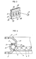
- the rotary support device of the present invention comprises an under ring including a horizontal portion and a peripheral wall projecting upward from the inner periphery of the horizontal portion and inclined either outward or inward, the wall being formed with a guide groove in a peripheral surface thereof, and an upper ring including a horizontal portion and a peripheral wall projecting downward from the inner periphery of the horizontal portion and inclined along the inclined under ring wall, the upper ring wall being formed with a guide groove in a peripheral surface thereof.
- a multiplicity of balls are rollably fitted in the guide grooves and interposed between the two rings.
- the under ring wall and the upper ring wall are engaged with each other rotatably and inseparably by the balls.
- the under ring peripheral wall and the upper ring peripheral wall rollably supporting the balls are inclined with respect to the axis of rotation, and the balls are adapted to withstand both radial load and thrust load at the same time.
- the device therefore has sufficient durablity and is simple in construction.
- the two rings are free of misalignment, rendering the device useful for precision work.
- the invention further provides a method of producing the rotary support device which comprises the steps of placing the multiplicity of balls in an annular arrangement into the guide groove of either one of the under and upper rings, arranging the two rings as opposed to each other concentrically, with the balls interposed therebetween and prevented from falling off by holding means, and pressing the rings against each other to elastically deform the ring walls and thereby fit the balls into the guide grooves of the rings.
- small devices can of course be produced similarly, for example, for use in drawing pictures on clay jars or pots or in trimming or taking care of potted plants.
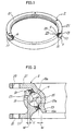
- each of an under ring 1 and an upper ring 2 is prepared from a shape steel member corresponding to the ring in cross section, by bending the member into a ring, about 2 m in diameter, using a bender, and welding opposite ends together.
- the under ring 1 comprises a horizontal portion 11 and a peripheral wall 13 projecting upward by a short distance from the inner periphery of the horizontal portion 11 and inclined outward with respect to the vertical direction.
- the upper ring 2 comprises a horizontal portion 21 and a peripheral wall 23 projecting downward by a short distance from the inner periphery of the horizontal portion 21 and inclined inward with respect to the vertical direction.
- the wall 13 of the under ring 1 has a diameter increasing toward its upper end, while the wall 23 of the upper ring 2 has a diameter decreasing toward its lower end in corresponding relation to the under ring wall 13.
- the upper ring wall 23 is fitted in the under ring wall 13 with a clearance formed therebetween.
- the ring walls 13, 23 are inclined at an angle of about 30 degrees with respect to the vertical direction, i.e., to the axis of rotation of the device.
- the peripheral wall 23 of the upper ring 2 has a vertical portion 23a, about 2 to 3 mm in length, at its lower end for preventing balls from falling off when the upper ring is pressed in as will be described later.
- the horizontal portions 11, 21 of the rings 1, 2 are formed respectively with holes 10 for inserting bolts or the like therethrough to fix the device to the floor, and with holes 20 for inserting bolts or the like therethrough to fix a pallet or like work table to the top of the device.
- Circumferential guide grooves 15, 25 are formed in the opposed faces of the peripheral walls 13, 23, respectively, approximately centally of their width.
- the wall surfaces defining the guide grooves 15, 25 are in the form of a circular arc subtending an angle of 150 degrees at the center of the ball 4 to be described below in conformity with the surface of the ball 4.
- a grease injection bore 17 is formed in the peripheral wall 13 of the under ring 1 and provided with a grease nipple (not shown).
- Balls 4 3/4 inch in diameter, are fitted in the guide grooves 15, 25 and arranged between the two rings at a pitch of about 30 mm.
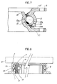
- the balls 4 are spaced at the specified distance by synthetic resin retainers 3 shown in Fig. 3.
- the retainer 3 comprises a strip 30 having five ball accommodating holes 31 arranged at equal spacings.
- the strip 30 has bifurcated lips 33, 33 formed at each side thereof and extending longitudinally thereof. The lips 33 are in contact with the respective ring walls 13, 23 to prevent ingress of dust or extraneous matter into the path of rolling of the balls 4.
- a required number of retainers 3 are used as arranged along the guide grooves in accordance with the size of the rings.
- the opposed surfaces of the rings 1, 2 defining the guide grooves 15, 26 partially cover the balls 4 from above and below, respectively, by an amount W which is about 4 mm. Accordingly, when the upper ring 2 is brought up, the balls 4 engage the outer side edges 15a, 25a of the respective grooved portions, thereby preventing the rings from separating from each other.
- peripheral walls 13, 23 of the rings 1, 2 rollably supporting the balls 4 are inclined and therefore permit the balls 4 to withstand both radial load and thrust load at the same time. This gives improved durability to the device although it is simple in construction.
- FIG. 2 can be of a construction corresponding to the device as turned upside down.
- Fig. 7 shows such an embodiment.
- the peripheral wall 13 of an under ring 1 projects upward from the inner periphery of its horizontal portion 11 and is inclined inward with respect to the vertical direction
- the peripheral wall 23 of an upper ring 2 projects downward from the inner periphery of its horizontal portion 21 and is inclined outward with respect to the vertical direction.
- guide grooves 15 and 25 are formed in the inner surface of the wall 13 and the outer surface of the wall 23 according to the embodiment shown in Fig. 2, these grooves 15, 25 can conversely be formed in the outer surface of the wall 13 and the inner surface of the wall 23. The same is true of the embodiment of Fig. 7.
- retainers 3 having balls 4 fitted therein are closely arranged along the guide groove 15 of the under ring 1, and the balls 4 are retained by holding means 5 so as not slip off the grooved portion 15.
- the holding means 5 is grease. Utilizing the adhering property of the grease, the balls 4 are held in the guide groove 15 against slipping off.
- the holding means can be suitable mechanical support means for preventing the balls from falling off the guide grooved portion.
- the ring peripheral walls 13, 23 are deformed away from each other, permitting the balls 4 to fit also into the guide groove 25 of the upper ring 2 (Fig. 2).
- the vertical portion 23a formed on the upper ring wall 23 serves to prevent the balls 4 from falling off the grooved portion 15 at this time as best seen in Fig. 4.
- a portion of the rotary support device is fitted in between two fixedly positioned rollers 91, 91 on a known bender 9 and correction rollers 92, 92 opposed to and movable toward or away from the respective rollers 91, 91 with the device placed on support rolls 93, 93 on opposite sides of the rollers 91, 91.
- the portion of the device left unsupported by the bender 9 is supported by a plurality of stands (not shown) so that the device is rotatable in a horizontal plane.
- a movable pressure roller 94 is moved toward a position between the fixed rollers 91, 91 to push the upper ring 2 with the roller 94, bringing the under ring 1 into contact with the fixed rollers 91, 91.
- the two fixed rollers 91, 91 are driven in the same direction, while the pressure roller 94 is driven in a direction opposite to the direction of rotation of the rollers 91.
- the rotation of these rollers rotates the upper ring 2 and the under ring 1 in directions opposite to each other.
- the correction rollers 92 are moved toward the fixed rollers 91 to press the wall 23 of the upper ring 2 outward.
- the upper ring wall 23 rotates while being subjected to a force acting to diametically enlarge the wall 23.
- the above operation also breaks in the balls 4 and the grooved rings 1, 2, rendering the balls 4 smoothly rotatable along the guide grooves 15, 25 even if these grooves are not finished by cutting to make the upper ring 2 smoothly rotatable.
- the breaking-in step may alternatively be so performed as to rotate the two rings relative to each other while pressing the peripheral wall of the outer ring inward.
- the under ring and the upper ring can be prepared by blanking with a press and bending the blanks.
- the guide grooves 15, 25 may be formed in the under ring and upper ring by recessing the peripheral walls 13, 23 to the shape of a groove by press work, and cutting the grooved portions in conformity with the spherical surface of the ball 4 when required.
- balls 4 are arranged in the guide groove of one of the rings, and the two rings are arranged as opposed to each other, with the balls 4 interposed therebetween and prevented from slipping off the grooved portion. In this state, the two rings are pressed against each other.
- the ring walls 13, 23 rollably supporting the balls 4 are in the form of a cone or inverted cone, and the balls 4 withstand both radial load and thrust load at the same time. This construction makes the device simple in construction.
- the two rings can be held in alignment with each other.
- the support device is usable for precision work.
- the device can be assembly merely by pressing the upper ring 2 against the under ring 1 with the balls 4 arranged on the ring 1.
- the device can therefore be produced by a simplified process at a reduced cost.
Landscapes
- Engineering & Computer Science (AREA)
- General Engineering & Computer Science (AREA)
- Mechanical Engineering (AREA)
- Rolling Contact Bearings (AREA)
- Workshop Equipment, Work Benches, Supports, Or Storage Means (AREA)
- Mounting Of Bearings Or Others (AREA)
Applications Claiming Priority (2)
| Application Number | Priority Date | Filing Date | Title |
|---|---|---|---|
| JP107930/88 | 1988-04-28 | ||
| JP10793088A JPH01279114A (ja) | 1988-04-28 | 1988-04-28 | 回転台 |
Publications (2)
| Publication Number | Publication Date |
|---|---|
| EP0339630A1 true EP0339630A1 (de) | 1989-11-02 |
| EP0339630B1 EP0339630B1 (de) | 1993-03-31 |
Family
ID=14471657
Family Applications (1)
| Application Number | Title | Priority Date | Filing Date |
|---|---|---|---|
| EP19890107619 Expired - Lifetime EP0339630B1 (de) | 1988-04-28 | 1989-04-27 | Drehbare Stützeinrichtung und deren Herstellungsverfahren |
Country Status (4)
| Country | Link |
|---|---|
| EP (1) | EP0339630B1 (de) |
| JP (1) | JPH01279114A (de) |
| AU (1) | AU609289B2 (de) |
| DE (1) | DE68905643T2 (de) |
Cited By (4)
| Publication number | Priority date | Publication date | Assignee | Title |
|---|---|---|---|---|
| EP1586524A3 (de) * | 2004-04-09 | 2006-05-31 | Z.M. di Zamuner Michele | Kabelabwickelvorrichtung |
| FR2901766A1 (fr) * | 2006-05-30 | 2007-12-07 | Snr Roulements Sa | Systeme d'actionnement compact d'arbre de direction comprenant un roulement a bagues en tole emboutie |
| GB2445756A (en) * | 2007-01-19 | 2008-07-23 | Jill Salmon | Rotating ring assembly unit |
| JP2017044268A (ja) * | 2015-08-26 | 2017-03-02 | Thk株式会社 | 旋回軸受 |
Families Citing this family (1)
| Publication number | Priority date | Publication date | Assignee | Title |
|---|---|---|---|---|
| CN114643563B (zh) * | 2022-04-24 | 2023-03-10 | 江苏鼎麒轴承有限公司 | 一种大型转盘轴承装配工作台 |
Citations (7)
| Publication number | Priority date | Publication date | Assignee | Title |
|---|---|---|---|---|
| GB447966A (en) * | 1935-05-29 | 1936-05-28 | Rothe Erde Eisenwerk | Ball bearing, especially for pivotal connections between a trailer and its support, and method of its manufacture |
| CH496182A (de) * | 1968-07-26 | 1970-09-15 | Skf Svenska Kullagerfab Ab | Wälzlager |
| DE2057187A1 (de) * | 1969-11-20 | 1971-06-03 | Riv Officine Di Villar Perosa | Verfahren und Vorrichtung zur Herstellung von Waelzlagern |
| DE2156081A1 (de) * | 1970-11-11 | 1972-05-18 | Rubber Plastics Ltd | Wälzlager |
| US3860301A (en) * | 1972-07-06 | 1975-01-14 | Skf Ind Trading & Dev | Rolling bearing with sheet metal rings and two rows of rolling bodies |
| US4027932A (en) * | 1974-05-25 | 1977-06-07 | Skf Industrial Trading And Development Company B.V. | Clutch release bearing |
| US4699527A (en) * | 1985-01-31 | 1987-10-13 | Schaeffler Walzlager GmbH, Homburg | Angular contact ball bearing with an out-of-round rim and method for assembling same |
Family Cites Families (3)
| Publication number | Priority date | Publication date | Assignee | Title |
|---|---|---|---|---|
| JPS4946040A (de) * | 1972-08-19 | 1974-05-02 | ||
| JPS54132044A (en) * | 1978-04-04 | 1979-10-13 | Koujirou Abe | Bearing |
| JPS5693516U (de) * | 1979-12-21 | 1981-07-25 |
-
1988
- 1988-04-28 JP JP10793088A patent/JPH01279114A/ja active Granted
-
1989
- 1989-04-27 DE DE1989605643 patent/DE68905643T2/de not_active Expired - Fee Related
- 1989-04-27 EP EP19890107619 patent/EP0339630B1/de not_active Expired - Lifetime
- 1989-04-27 AU AU33824/89A patent/AU609289B2/en not_active Ceased
Patent Citations (7)
| Publication number | Priority date | Publication date | Assignee | Title |
|---|---|---|---|---|
| GB447966A (en) * | 1935-05-29 | 1936-05-28 | Rothe Erde Eisenwerk | Ball bearing, especially for pivotal connections between a trailer and its support, and method of its manufacture |
| CH496182A (de) * | 1968-07-26 | 1970-09-15 | Skf Svenska Kullagerfab Ab | Wälzlager |
| DE2057187A1 (de) * | 1969-11-20 | 1971-06-03 | Riv Officine Di Villar Perosa | Verfahren und Vorrichtung zur Herstellung von Waelzlagern |
| DE2156081A1 (de) * | 1970-11-11 | 1972-05-18 | Rubber Plastics Ltd | Wälzlager |
| US3860301A (en) * | 1972-07-06 | 1975-01-14 | Skf Ind Trading & Dev | Rolling bearing with sheet metal rings and two rows of rolling bodies |
| US4027932A (en) * | 1974-05-25 | 1977-06-07 | Skf Industrial Trading And Development Company B.V. | Clutch release bearing |
| US4699527A (en) * | 1985-01-31 | 1987-10-13 | Schaeffler Walzlager GmbH, Homburg | Angular contact ball bearing with an out-of-round rim and method for assembling same |
Cited By (8)
| Publication number | Priority date | Publication date | Assignee | Title |
|---|---|---|---|---|
| EP1586524A3 (de) * | 2004-04-09 | 2006-05-31 | Z.M. di Zamuner Michele | Kabelabwickelvorrichtung |
| FR2901766A1 (fr) * | 2006-05-30 | 2007-12-07 | Snr Roulements Sa | Systeme d'actionnement compact d'arbre de direction comprenant un roulement a bagues en tole emboutie |
| GB2445756A (en) * | 2007-01-19 | 2008-07-23 | Jill Salmon | Rotating ring assembly unit |
| JP2017044268A (ja) * | 2015-08-26 | 2017-03-02 | Thk株式会社 | 旋回軸受 |
| KR20180042261A (ko) * | 2015-08-26 | 2018-04-25 | 티에치케이 가부시끼가이샤 | 선회 베어링 |
| EP3343051A4 (de) * | 2015-08-26 | 2018-09-05 | Thk Co., Ltd. | Grosswälzlager |
| US20180266484A1 (en) * | 2015-08-26 | 2018-09-20 | Thk Co., Ltd. | Slewing bearing |
| KR102557235B1 (ko) | 2015-08-26 | 2023-07-19 | 티에치케이 가부시끼가이샤 | 선회 베어링 |
Also Published As
| Publication number | Publication date |
|---|---|
| DE68905643D1 (de) | 1993-05-06 |
| JPH01279114A (ja) | 1989-11-09 |
| AU3382489A (en) | 1989-11-02 |
| EP0339630B1 (de) | 1993-03-31 |
| DE68905643T2 (de) | 1993-10-21 |
| JPH0547727B2 (de) | 1993-07-19 |
| AU609289B2 (en) | 1991-04-26 |
Similar Documents
| Publication | Publication Date | Title |
|---|---|---|
| US5174538A (en) | Rotary support device | |
| US4815862A (en) | Self-contained linear bearing unit and linear bearings embodying such units | |
| JPH0788848B2 (ja) | 複列アンギュラコンタクト球軸受の製造方法 | |
| US7637664B2 (en) | Composite roll bearing | |
| EP0339630B1 (de) | Drehbare Stützeinrichtung und deren Herstellungsverfahren | |
| JPS6098216A (ja) | 接触角をもつ軸受を備えた回転支持装置 | |
| US6186669B1 (en) | Roller cage for roller bearing | |
| CA1228106A (en) | Rotary support device | |
| JP2005090740A (ja) | ころ軸受用保持器の製造方法及びころ軸受用保持器 | |
| US20080112657A1 (en) | Linear guide device and method for designing or forming raceway groove thereof | |
| GB2054764A (en) | Linear ball bearing unit and method for manufacturing same | |
| JP2020070857A (ja) | 旋回軸受 | |
| WO1997041363A1 (fr) | Unite de guidage de deplacement lineaire et dispositif de guidage de table faisant appel a cette unite | |
| JP3261813B2 (ja) | 転がり軸受用保持器 | |
| JP2021124141A (ja) | 転がり軸受の製造方法、並びに機械及び車両の製造方法 | |
| CA2000304C (en) | Device for supporting arm driving shafts of industrial robot | |
| US7600922B2 (en) | Ball roller rolling member | |
| KR101192029B1 (ko) | 볼 베어링용 리테이너 및 그 제조방법 | |
| JP2877994B2 (ja) | 直線摺動用軸受 | |
| JPH10220481A (ja) | ころ軸受用のころ保持器及び該ころ保持器の取り付け方法及び装置 | |
| JP2538724Y2 (ja) | スライド軸受 | |
| JPH0623679A (ja) | 回転台 | |
| CN116398540B (zh) | 圆锥滚子轴承用冲压保持架、加工方法及加工用的冲子 | |
| KR200198328Y1 (ko) | 스러스트 니이들베어링 리테이너 구조 | |
| JPS645130Y2 (de) |
Legal Events
| Date | Code | Title | Description |
|---|---|---|---|
| PUAI | Public reference made under article 153(3) epc to a published international application that has entered the european phase |
Free format text: ORIGINAL CODE: 0009012 |
|
| AK | Designated contracting states |
Kind code of ref document: A1 Designated state(s): DE FR GB IT |
|
| 17P | Request for examination filed |
Effective date: 19891220 |
|
| 17Q | First examination report despatched |
Effective date: 19910403 |
|
| GRAA | (expected) grant |
Free format text: ORIGINAL CODE: 0009210 |
|
| AK | Designated contracting states |
Kind code of ref document: B1 Designated state(s): DE FR GB IT |
|
| ITF | It: translation for a ep patent filed | ||
| REF | Corresponds to: |
Ref document number: 68905643 Country of ref document: DE Date of ref document: 19930506 |
|
| ET | Fr: translation filed | ||
| PLBE | No opposition filed within time limit |
Free format text: ORIGINAL CODE: 0009261 |
|
| STAA | Information on the status of an ep patent application or granted ep patent |
Free format text: STATUS: NO OPPOSITION FILED WITHIN TIME LIMIT |
|
| 26N | No opposition filed | ||
| PGFP | Annual fee paid to national office [announced via postgrant information from national office to epo] |
Ref country code: FR Payment date: 19950328 Year of fee payment: 7 |
|
| PGFP | Annual fee paid to national office [announced via postgrant information from national office to epo] |
Ref country code: GB Payment date: 19950419 Year of fee payment: 7 |
|
| PGFP | Annual fee paid to national office [announced via postgrant information from national office to epo] |
Ref country code: DE Payment date: 19950428 Year of fee payment: 7 |
|
| PG25 | Lapsed in a contracting state [announced via postgrant information from national office to epo] |
Ref country code: GB Effective date: 19960427 |
|
| GBPC | Gb: european patent ceased through non-payment of renewal fee |
Effective date: 19960427 |
|
| PG25 | Lapsed in a contracting state [announced via postgrant information from national office to epo] |
Ref country code: FR Effective date: 19961227 |
|
| PG25 | Lapsed in a contracting state [announced via postgrant information from national office to epo] |
Ref country code: DE Effective date: 19970101 |
|
| REG | Reference to a national code |
Ref country code: FR Ref legal event code: ST |
|
| PG25 | Lapsed in a contracting state [announced via postgrant information from national office to epo] |
Ref country code: IT Free format text: LAPSE BECAUSE OF NON-PAYMENT OF DUE FEES;WARNING: LAPSES OF ITALIAN PATENTS WITH EFFECTIVE DATE BEFORE 2007 MAY HAVE OCCURRED AT ANY TIME BEFORE 2007. THE CORRECT EFFECTIVE DATE MAY BE DIFFERENT FROM THE ONE RECORDED. Effective date: 20050427 |