EP0340221B1 - Systeme d'enregistrement a carte multiple - Google Patents
Systeme d'enregistrement a carte multiple Download PDFInfo
- Publication number
- EP0340221B1 EP0340221B1 EP87907883A EP87907883A EP0340221B1 EP 0340221 B1 EP0340221 B1 EP 0340221B1 EP 87907883 A EP87907883 A EP 87907883A EP 87907883 A EP87907883 A EP 87907883A EP 0340221 B1 EP0340221 B1 EP 0340221B1
- Authority
- EP
- European Patent Office
- Prior art keywords
- data
- drum
- cards
- card
- light beam
- Prior art date
- Legal status (The legal status is an assumption and is not a legal conclusion. Google has not performed a legal analysis and makes no representation as to the accuracy of the status listed.)
- Expired - Lifetime
Links
Images

Classifications
-
- G—PHYSICS
- G06—COMPUTING OR CALCULATING; COUNTING
- G06K—GRAPHICAL DATA READING; PRESENTATION OF DATA; RECORD CARRIERS; HANDLING RECORD CARRIERS
- G06K1/00—Methods or arrangements for marking the record carrier in digital fashion
- G06K1/12—Methods or arrangements for marking the record carrier in digital fashion otherwise than by punching
- G06K1/126—Methods or arrangements for marking the record carrier in digital fashion otherwise than by punching by photographic or thermographic registration
-
- G—PHYSICS
- G11—INFORMATION STORAGE
- G11B—INFORMATION STORAGE BASED ON RELATIVE MOVEMENT BETWEEN RECORD CARRIER AND TRANSDUCER
- G11B27/00—Editing; Indexing; Addressing; Timing or synchronising; Monitoring; Measuring tape travel
- G11B27/02—Editing, e.g. varying the order of information signals recorded on, or reproduced from, record carriers
- G11B27/031—Electronic editing of digitised analogue information signals, e.g. audio or video signals
-
- G—PHYSICS
- G11—INFORMATION STORAGE
- G11B—INFORMATION STORAGE BASED ON RELATIVE MOVEMENT BETWEEN RECORD CARRIER AND TRANSDUCER
- G11B5/00—Recording by magnetisation or demagnetisation of a record carrier; Reproducing by magnetic means; Record carriers therefor
- G11B5/86—Re-recording, i.e. transcribing information from one magnetisable record carrier on to one or more similar or dissimilar record carriers
-
- G—PHYSICS
- G11—INFORMATION STORAGE
- G11B—INFORMATION STORAGE BASED ON RELATIVE MOVEMENT BETWEEN RECORD CARRIER AND TRANSDUCER
- G11B7/00—Recording or reproducing by optical means, e.g. recording using a thermal beam of optical radiation by modifying optical properties or the physical structure, reproducing using an optical beam at lower power by sensing optical properties; Record carriers therefor
- G11B7/002—Recording, reproducing or erasing systems characterised by the shape or form of the carrier
- G11B7/0025—Recording, reproducing or erasing systems characterised by the shape or form of the carrier with cylinders or cylinder-like carriers or cylindrical sections or flat carriers loaded onto a cylindrical surface, e.g. truncated cones
-
- G—PHYSICS
- G11—INFORMATION STORAGE
- G11B—INFORMATION STORAGE BASED ON RELATIVE MOVEMENT BETWEEN RECORD CARRIER AND TRANSDUCER
- G11B7/00—Recording or reproducing by optical means, e.g. recording using a thermal beam of optical radiation by modifying optical properties or the physical structure, reproducing using an optical beam at lower power by sensing optical properties; Record carriers therefor
- G11B7/002—Recording, reproducing or erasing systems characterised by the shape or form of the carrier
- G11B7/0033—Recording, reproducing or erasing systems characterised by the shape or form of the carrier with cards or other card-like flat carriers, e.g. flat sheets of optical film
-
- G—PHYSICS
- G11—INFORMATION STORAGE
- G11B—INFORMATION STORAGE BASED ON RELATIVE MOVEMENT BETWEEN RECORD CARRIER AND TRANSDUCER
- G11B7/00—Recording or reproducing by optical means, e.g. recording using a thermal beam of optical radiation by modifying optical properties or the physical structure, reproducing using an optical beam at lower power by sensing optical properties; Record carriers therefor
- G11B7/28—Re-recording, i.e. transcribing information from one optical record carrier on to one or more similar or dissimilar record carriers
Definitions
- the present invention relates to a data card recording system as described in the pre-characterizing part of claim 1.
- a data card recording system as described in the pre-characterizing part of claim 1.
- Such system is known from US-A-4,260,998.
- US-A-4,360,728 discloses a data card writing and reading system in which a laser light source emits a beam directed to a card.
- a first servo controlled mirror is mounted for rotation in order to find the lateral edges of laser recording material on the card in a coarse mode of operation and then in a fine node of operation identify data paths which exist predetermined distances from the edges.
- a second servo controlled mirror is mounted for rotation in order to scan the beam in a fine mode of operation along the length of the card. Coarse control of the lengthwise position of the card is achieved by motion of a movable holder supporting the card.
- the beam produces light scattering pits representing data bits in the laser recording material.
- the data are read by a photodetector detecting differences in reflectivity between a pit and surrounding material using a reduced power laser beam.
- US-A-3,654,624 discloses a laser recording system in which a flat elongated record strip is wound around the surface of a drum.
- the drum is rotated with respect to the laser beam during recording and reproducing operations.
- the laser beam is moved transversely to the direction of drum rotation to permit selection of any one of a large number of spaced parallel scan lines on the record strip.
- US-A-4,578,717 discloses a magnetic recording and reproducing apparatus in which a flexible magnetic record card is retained against a surface of a drum to permit suitable magnetic transducing to be effected while the card is rotated with a drum and the transducers are properly aligned with a selected circular track of the card.
- this apparatus is not suitable for card duplication.
- US-A-3,512,130 discloses a drum having arranged on its circumference a plurality of opaque account cards.
- the purpose of the drum is for comparing two different kinds of cards passing a linear opening in a mask.
- the recordings on the cards randomly differ from each other. There is no track forming or track recording or track following at all.
- US-A-4,390,176 discloses a sheet clamping device in which a sheet is disposed around the peripheral surface of a drum rotating in a given direction.
- the device has gripping means set in the circumference of the drum and aligned transversely to the direction of the drum rotation whereby the longitudinal ends of one sheet can be retained by pressure of said gripping means.
- US-A-4,074,282 discloses a record structure for recording with a radiation beam.
- the record structure uses a drum on which the data storage media is supported and which is covered with a transparent cylinder jacket which is transmissive to the light beam.
- US-A-4,260,998 discloses a recording system as defined in the pre-characterizing part of claim 1 which produces a plurality of hard copies from a single input image signal.
- the recording device comprises a scan converter which stores the input image signal and repeatedly reads out the signal, an acousto-optic modulator which is supplied with a stored image signal from the scan converter and modulates a recording light beam of a laser with the supplied image signal, and a deflector which deflects the modulated recording light beam to scan a plurality of photosensitive recording media to record the image signal thereon.
- the recording media are supported on the inner surface of a cylindrical support member. With this arrangement the modulated laser beam is swept transversely of the recording media. As all the stored image signals are recorded in parallel on all the recording media, the recording mode is time-consuming.
- An object of the present invention is to produce a high speed data card recording system which is capable of handling the high volume demands of electronic publishing, card duplicating and the like.
- a data card recording system which records identical data on each of a plurality of data cards supported around the circumferential surface of a drum.
- the drum is mounted for rotation and may have flanges set in the circumference for disposing the data cards on said drum in a longitudinally skewed fashion.
- the drum may comprise a pair of concentric cylinders in which the cards are mounted between the cylinders in such a longitudinally skewed fashion.
- a light source emits a light beam which is directed along an optical path to the cards.
- the drum may be transmissive to the light beam or have openings or transmissive windows where the card is mounted on the inside rather than on the outside of the drum.
- the system also includes a data control circuit in communication with a data source and having at least one memory location for storing a data segment to be recorded onto the data cards.
- a modulator electrically connected to the data control circuit and positioned in the optical path modulates the light beam in response to the data segment.
- Each of the cards has a strip of laser recordable optical data storage material disposed thereon, so that as the drum rotates, the modulated beam produces data spots corresponding to the stored data segment in one of a plurality of parallel tracks on each of the data cards on the drum.
- Tracks of data are aligned in the direction of drum rotation.
- the relative transverse position between the beam and the cards is movable continuosly, as by moving an element in the beam path, so that additional data segments may be recorded in multiple parallel tracks on each of the cards.
- the data control circuit in communication with a drive control drives the light beam modulation at a rate which is synchronized to the drum speed. Recording is complete when the data cards are each filled with identical information or when all data segments have been recorded.
- a photodetector may be positioned for reading a track on a card, measuring changes in optical contrast defined by data spots formed on the track, and thereby verify that data recording is accurate.
- the same or another photodetector may provide autofocus control of the light beam.
- the same or still another photodetector may provide servo tracking of the light beam.
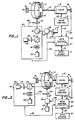
- a data card recording system includes a rotatable drum 11 supporting a plurality of data cards 13 bent around the drum circumferential surface.
- Each data card comprises a card base 14 and a strip 15 of laser recordable optical storage material disposed on base 14.
- Data cards are typically wallet sized with a width dimension of approximately 54 mm and a length dimension of approximately 85 mm. These dimensions are not critical, but preferred because such a size easily fits into a wallet and has been adopted as a conventional size for automatic teller machines and the like.
- an 11 inch (27.9 cm) diameter drum is capable of supporting 10 cards, as shown in Fig. 1. Smaller drums, such as the drums in Figs. 3-8 with a diameter of approximately 5 inches (12.7 cm), support as few as four cards, while larger diameter drums will support more than 10 cards.
- Card base 14 is a dielectric, usually a plastic material, such as polycarbonate, polyvinylchloride or similar material. Alternatively, card base 14 may be a metal film. Card base 14 may be either opaque or transparent. Card base 14 must be transparent when used with strips 15 which are transmissively read. Strip 15 is typically about 10 mm to 54 mm wide and extends the length of the card. The strip may be applied by any convenient method which achieves flatness and adherence to the card base. A transparent protective laminating sheet made of polycarbonate plastic or other material may cover strip 15 to protect it from dust and scratches.
- the laser recordable optical data storage material which forms strip 15 may be one of the reflective recording materials which have been developed having direct-read-after-write capability.
- Typical recording media are described in U.S. patent Nos. 4,314,260, 4,278,758, 4,278,756, 4,298,684, 4,269,917 and 4,284,716, all assigned to the assignee of the present invention. These media contain suspensions of reflective metal particles in organic colloids and form highly reflective low melting temperature laser recordable media. Data are recorded by forming reduced reflectivity spots which contrast with the surrounding field of the reflective layer itself.
- Reflectivity of the strip field of about 50% with a reflectivity of a spot in the field of less than 10% is preferred, thus creating a contrast ratio of at least five to one, although a contrast ratio of two to one or even lower is sufficient for reading the data.
- media which have reflective spots in a low reflectivity field may be used.
- Media which are read by light transmission through the card may also be used.
- Erasable materials, such as magneto-optic and amorphous-to-crystalline recording materials, may also be used.
- Drum 11 is rotatable about a drive shaft 17 on the drum cylindrical axis, as indicated by arrow A.
- a motor 19 to which drive shaft 17 is connected provides rotary power for turning drum 11.
- drum 11 rotates at a speed from about 150 to 1800 rpm.
- a position encoder 18 measures the speed of rotation and also indicates the completion of each drum rotation.
- a laser 21 emits a laser light beam 23 directed along an optical path to card 13 mounted on drum 11.
- a modulator 25 positioned in the optical path modulates the light beam 23 in response to data.
- the resulting modulated beam 27 is focussed onto an optical data storage strip 15 of a card 13 on the drum 11 by means of focussing optics 29.
- current modulation may be used for a semiconductor laser.
- the lateral position of drum 11 may be changed by altering the length of shaft 17 between drum 11 and motor 19 with a solenoid. Alternatively, a stepper motor may be used.
- the focussing beam should deliver sufficient laser pulse energy to the surface of the recording material to create spots. Typically, 10-40 milliwatts is required, depending on the recording material.
- the wavelength of the laser 21 should be compatible with the recording material.
- a data source 31 is connected to a data control circuit 33 via a data bus 35.
- Data source 31 may be semiconductor memory internal to the card writing system or may be an external peripheral device such as an optical card reader, disk drive or keyboard. When data source 31 is an optical card reader the entire system could be called a card duplicator.
- Data control circuit 33 is typically a microprocessor and includes at least one data register 37 for storing a data segment read from data source 31. Data control circuit 33 produces as output an electrical signal corresponding to the data segment stored in register 37 which is transmitted along a line 39 to modulator 25 so as to modulate laser light beam 23 in response to the data segment. The electrical signal output is produced as many times as there are data cards 13 on drum 11 for the same data segment so that each card records identical information.
- the length of a data segment is preferably equal to the amount of data necessary to record one complete track on a data card.
- data control circuit 33 After a track of data has been recorded on each data card 13 on drum 11, data control circuit 33 produces an electrical signal output corresponding to another data segment for recording on an adjacent track on each card.
- data control circuit 33 has a second data register like register 37 to read and store the next data segment while the signals for the current data segment are being output.
- Data control 33 receives via bus 42 a synchronizing signal from position encoder 18 after each drum revolution. Data control 33 may then send a signal via bus 49 to reposition unit 47 to the next track. Recording continues until all data in data source 31 are recorded or until data cards 13 are filled.
- Data control circuit 33 also communicates with a drive control or servo 41 via a bus 43.
- Drive control 41 sends electrical signals along a line 45 to motor 19 to cause motor 19 to start, stop, speed up or slow down.
- data control circuit 33 and drive control 41 synchronize the light beam modulation with the rotary speed of the drum.
- the rotation speed is sensed using position encoder 18. This signal is used by data control 33 to synchronize the modulation rate of modulator 25 with the rotation speed of drum 11.
- a detector unit 47 may be disposed in reading relation relative to a track for providing feedback to data control circuit 33 and drive control 41. Detector unit 47 communicates with these control elements 33 and 41 via an electric signal line 49.
- data cards 13 are read by reflection, so that detector unit 47 is positioned in a light reflective relation relative to cards 13 on drum 11.
- a beamsplitter 51 may be used to direct modulated beam 27 to cards 13 and to direct reflected light from cards 13 to one or more detectors 59 and 63.
- data cards 13 are read by light transmission, so that detector unit 47 is positioned in a light tranmissive relation relative to cards 13.
- a mirror 53 inside drum 11 may be used to direct transmitted light from cards 13 to one or more detectors 59 and 63.
- a second beamsplitter 55 directs a portion of the light from cards 13 through a focussing lens 57 onto a reading detector 59, and a second portion through a lens doublet 61 onto an autofocus detector 63.
- Typically 50% of the light is directed to reading detector 59 and 50% of the light is directed to autofocus detector 63.
- Autofocus detector 63 communicates with focussing optics 29 via bus 65 to effect a change in either the focal length of focussing optics 29 or the distance between focussing optics 29 and a card 13 on drum 11, thereby bringing the modulated beam 27 into a sharp focus onto card 13.
- Reading detector 59 reads data as or just after data are written by sensing changes in optical contrast defined by data spots formed on a track of the card so as to verify proper data recording. Detector 59 may also be used to read prerecorded clocking marks, beginning and end of track marks and other track codes to aid in the synchronisation of data writing. Prerecorded marks may not be necessary in precision high speed recorders.
- the recording beam move smoothly in the absence of track guides rather than in steps.
- the beam can be moved in a uniform manner in a helical scan by means of a precision screw.
- the card be mounted in a skew fashion and each card be offset from the next. The degree of skew and offset would be determined by the data track pitch.
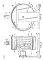
- a drum 67 is rotatably mounted on a shaft 69 and driven by a motor 71.
- the drum may be mounted for rotation about either a horizontal or vertical axis.
- a base 73 supports a frame 75 which has an upright arm 77 to which motor 71 is mounted.
- the drum depicted has a circumferential surface 79 sufficiently large to accommodate four wallet size data cards 81 that are 85 mm long. As noted above, larger drums which can accommodate a greater number of data cards may also be used and are similarly constructed.
- Focussing optics 29 having at least one lens 30 are located outside of drum 79 for focussing a modulated light beam for writing data spots 85 onto cards 81.
- Focussing optics 29 may also direct reflected light from cards 81 to a detector unit 47, shown in Fig. 1.
- Servo track guides 83 may be provided on cards 81 for feedback and motor control in reading and writing the spots 85 in tracks between the track guides. Track guides 83 are aligned in the direction of travel of the rotating drum, indicated by arrow A. Servo track guides 83 may not be necessary in precision high speed recorders. Alternatively, track guides and other indicia may be written with the laser as the data are being written on cards which have no prerecorded indicia.
- Drum 67 comprises a circumferential surface or cylinder 79 and a circular side wall 87 connected to one edge of cylinder 79.
- a plurality of transverse flanges 89 are spaced around the circumference of the drum for support and retention of the data cards.
- Motor shaft 69 may be directly mounted to side wall 87, as shown in Fig. 3, or alternatively may be offset and the drum driven by means of a connecting pulley and drive shaft mounted to either side wall 87 or a disk in rim 91 opposite from side wall 87.
- Data cards 30 are fastened to the outer circumferential surface 79 of the drum by means of grooves 93 and 94 in the sides of transverse flanges 89.
- the data cards 81 are somewhat flexible and may be bent, as shown in phantom in Fig. 4, so as to slide into grooves 93 and 94 of flanges 89.
- an alternate embodiment of a drum 95 comprises two concentric cylinders 97 and 99 having a card retention slot 101 between the two cylinders 97 and 99.
- a plurality of data cards may be mounted in slot 101.
- the outer cylinder 99 is transmissive to the modulated laser light beam used for recording on the cards and may either be formed of transmissive plastic or comprise a metal frame structure 103 with transmissive windows 105.
- the windows 105 may either consist of open areas in the frame 103 or be formed or transmissive plastic, glass or other material set in the frame.
- the inner cylinder 97 may be formed of transmissive material or comprise a frame with transmissive windows.
- the inner cylinder need not be transmissive to the recording light beam when using reflectively read data cards, and may be formed from a solid opaque material, such as metal. When used to support transmissively read cards in the configuration shown in Fig. 2, both the outer and inner cylinders must be transmissive.
- Frame 103 of outer cylinder 99 has a pair of rings 107 and 109 joined by means of struts 111. Struts 111 may extend inward to inner cylinder 97 thereby providing transverse barriers in slot 101 to keep cards from slipping.
- a solid base 112 is attached to ring 107 and inner cylinder 97 providing means for mounting motor shaft 113. Slot 101 is open at one edge, opposite from base 112, allowing access into slot 101 for the data cards.
- a drum 115 comprises a frame 117 having windows 119.
- Windows 119 may be open areas, as shown, or alternatively, be formed of transmissive material, such as glass or plastic.
- Frame 117 has a pair of rings 121 and 123 joined by struts 125. Each strut has flanges 127 attached on the inside surface thereto, with grooves 129 in the flanges 127 for retaining data cards.
- a solid base 131 is attached to one of the rings for mounting a motor shaft 133 to the drum.
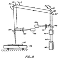
- an optical card reader which may form the data source 31 in the systems of Figs. 1 and 2, has a master data card 141 disposed in reading relation thereto.
- the card 141 is usually received in a movable holder 142 which brings the card into the read beam trajectory.
- a light source 143 such as a semiconductor laser or light emitting diode emits a beam 145, typically of near infrared wavelength, which passes through collimating and focussing optics 147.
- the beam may be sampled by a beam splitter 149 which transmits a portion of the beam through a focussing lens 151 to a photodetector 153.
- the detector 153 confirms that the read beam is on and of a constant power level. Power is about 5% of the power needed to record on the card. Detector 153 is optional.
- the beam is then directed to a first servo controlled mirror 155 which is mounted for rotation along the axis 157 in the direction indicated by arrows B.
- the purpose of mirror 155 is, in a coarse mode, to find the lateral edges of the optical data storage material on card 141 and then in a fine mode of operation to identify data paths which exist predetermined distances from the edges.
- Fig. 9 the lengthwise dimension of the card 141 is shown.
- the beam is directed toward mirror 161.
- This mirror is mounted for rotation at pivot 163.
- the purpose of mirror 161 is for fine control of motion of the beam along the length of the card. Coarse control of the lengthwise position of the card relative to the beam is achieved by motion of movable holder 142.
- the position of the holder may be established by a linear motor adjusted by a closed loop position servo system of the type used in magnetic disk drives.
- the card may have prerecorded or laser recorded reference position information such as servo tracks and timing marks, as well as program instructions and related functions. These position marks can be used as a reference for the optical card reader to read data at particular locations. Upon reading one data path, mirror 155 is rotated slightly so that the next data path can be read.
- Light scattered and reflected from data spots contrasts with the surrounding field where no spots exist.
- Optical contrast between a spot and surrounding field is detected by light detector 165 and focussing lens 169.
- the detector 165 produces electrical signals corresponding to spots. These signals may be sent along bus 35 to data control 33 in Figs. 1 and 2 for storage of a data segment corresponding to a track of data on master data card 141.
- Servo motors not shown, drive the mirrors 155 and 161 in the optical card reader in accord with instructions received from data control 33.
- a high speed data card recording system useful for card duplication such as in on-demand publishing.
- the system is capable of recording several data cards at once with the same data, at an average speed of two minutes per card. Instead of taking three weeks to record one thousand cards, the job can be completed in less than a day and a half.
- the use of rotating drums not only enable multi-card recording, but also simplifies synchronization of card position with data compared to prior reciprocating systems, resulting in fewer recording errors.
Landscapes
- Engineering & Computer Science (AREA)
- Multimedia (AREA)
- Physics & Mathematics (AREA)
- General Physics & Mathematics (AREA)
- Theoretical Computer Science (AREA)
- Optical Recording Or Reproduction (AREA)
- Moulds For Moulding Plastics Or The Like (AREA)
- Injection Moulding Of Plastics Or The Like (AREA)
Abstract
Claims (11)
- Système d'enregistrement de cartes de données comprenant :
une pluralité de cartes de données (13, 81) ayant chacune une bande (15) d'un matériau de mémorisation de données optiques enregistrables par laser disposé dans celle-ci, ladite bande (15) se prolongeant dans le sens de la longueur de la carte et procurant une pluralité de pistes parallèles,
un tambour monté de manière rotative (11, 67, 95, 115) comportant des moyens (89) pour maintenir ladite pluralité des cartes de données autour de la surface circonférentielle du tambour (79),
des moyens (33, 37) en communication avec une source de données (31) pour stocker un segment de données numériques,
une source de lumière (21) émettant un faisceau lumineux, ledit faisceau étant dirigé et focalisé suivant un trajet optique vers ladite pluralité de cartes de données (13, 81),
un moyen (25) pour moduler ledit faisceau lumineux en réponse audit segment de données, ledit faisceau produisant des points de données correspondant audit segment de données dans une piste de ladite multitude des pistes parallèles sur chacune desdites cartes de données (13, 81) en séquence, une carte après l'autre, et
des moyens pour déplacer la position transversale relative entre ledit faisceau et ladite pluralité des cartes de données (13, 81), des segments de données supplémentaires étant enregistrés dans d'autres pistes de ladite pluralité des pistes parallèles sur chacune desdites cartes de données,
caractérisé en ce que
lesdits moyens de maintien (89) disposent ladite pluralité des cartes de données (13, 81) sur ledit tambour (11, 67, 95, 115) de manière longitudinalement décalée, chaque carte étant décalée de la carte suivante d'une distance fonction du pas de piste désiré , lesdits moyens pour déplacer ladite position transversale relative étant mis en oeuvre en continu et ledit faisceau lumineux ayant une taille sur ladite carte d'au plus cinq microns. - Système selon la revendication 1,
dans lequel lesdits moyens de maintien comprennent des rebords (89) fixés dans la circonférence du tambour (67) et alignés décalés par rapport à la direction du sens de rotation du tambour, d'où il résulte que les extrémités longitudinales de ladite pluralité des cartes de données (13, 81) sont maintenues par la pression desdits rebords (89). - Système selon la revendication 2,
dans lequel ladite pluralité des cartes de données (13, 81) sont supportées autour de l'extérieur de ladite surface circonférentielle du tambour (79). - Système selon la revendication 2,
dans lequel ladite pluralité des cartes de données (13, 81) sont supportées contre l'intérieur de ladite surface circonférencielle du tambour (79), ledit tambour (95, 115) laissant passer le faisceau lumineux. - Système selon la revendication 1,
dans lequel ledit tambour (95) comprend deux cylindres concentriques (97, 99) et ladite pluralité des cartes de données (13, 81) sont montées entre lesdits cylindres, au moins le cylindre extérieur (99) parmi lesdits cylindres laissant passer ledit faisceau de lumière. - Système selon la revendication 1,
dans lequel ledit tambour (115) comprend une paire d'éléments de cadre circulaires concentriques espacés (121, 123) et une pluralité de barres (125) entre ceux-ci raccordant ladite paire d'éléments de cadre (121, 123) ensemble. - Système selon la revendication 6,
dans lequel, des fenêtres (119) laissant passer ledit faisceau lumineux sont prévues dans au moins un desdits éléments de cadre (121, 123) entre lesdites barres (125). - Système selon la revendication 1,
comprenant de plus un moyen de détecteur (59) disposé en relation de lecture par rapport à une piste pour détecter des changements dans les contrastes optiques définis dans des points de données (85) formés sur ladite piste, ledit matériau de stockage de données optiques enregistrables par laser étant un matériau à lecture directe après écriture. - Système selon la revendication 8,
dans lequel ladite source de lumière (21) et ledit moyen de détecteur (59) sont en relation de réflection de lumière par rapport audit tambour (11, 67, 95) et auxdites cartes de données (13, 81). - Système selon la revendication 8, dans lequel ladite source de lumière (21) et ledit moyen de détecteur (59) sont en relation de transmission de lumière par rapport audit tambour (11, 115) et auxdites cartes de données (13, 81).
- Système selon la revendication 1,
comprenant de plus un moyen (41) en communication avec ledit moyen de mémorisation de segment de données pour entrainer ledit tambour (11, 67, 95, 115) à une vitesse de rotation synchronisée avec la modulation du faisceau lumineux.
Applications Claiming Priority (3)
| Application Number | Priority Date | Filing Date | Title |
|---|---|---|---|
| US06/937,648 US4820913A (en) | 1986-12-02 | 1986-12-02 | Multiple card recording system |
| PCT/US1987/002893 WO1988004455A1 (fr) | 1986-12-02 | 1987-11-05 | Systeme d'enregistrement a carte multiple |
| US937648 | 1992-08-31 |
Publications (3)
| Publication Number | Publication Date |
|---|---|
| EP0340221A1 EP0340221A1 (fr) | 1989-11-08 |
| EP0340221A4 EP0340221A4 (fr) | 1990-01-08 |
| EP0340221B1 true EP0340221B1 (fr) | 1994-06-01 |
Family
ID=25470220
Family Applications (1)
| Application Number | Title | Priority Date | Filing Date |
|---|---|---|---|
| EP87907883A Expired - Lifetime EP0340221B1 (fr) | 1986-12-02 | 1987-11-05 | Systeme d'enregistrement a carte multiple |
Country Status (6)
| Country | Link |
|---|---|
| US (2) | US4820913A (fr) |
| EP (1) | EP0340221B1 (fr) |
| JP (1) | JPH02501517A (fr) |
| CA (1) | CA1292312C (fr) |
| DE (1) | DE3789970D1 (fr) |
| WO (1) | WO1988004455A1 (fr) |
Families Citing this family (21)
| Publication number | Priority date | Publication date | Assignee | Title |
|---|---|---|---|---|
| US5089693A (en) * | 1986-12-02 | 1992-02-18 | Drexler Technology Corporation | Reader/writer for arcuately flexed data cards |
| US5107099A (en) * | 1989-04-24 | 1992-04-21 | Smith Malcolm G | Magnetic card reader and method |
| US5477023A (en) * | 1993-04-23 | 1995-12-19 | Westinghouse Electric Corporation | Laser engraving system and method for engraving an image on a workpiece |
| US5592462A (en) * | 1994-12-30 | 1997-01-07 | Beldock; Donald T. | Three-dimensional optical data storage and retrieval |
| NO952545D0 (no) * | 1995-06-23 | 1995-06-23 | Opticon As | Fremgangsmåte til skriving av data i et optisk minne |
| US5780829A (en) * | 1997-01-31 | 1998-07-14 | Mustek Systems Inc. | Flat-plate scanner having a beam-splitting prism/mirror and two light emitting sources |
| US6145742A (en) * | 1999-09-03 | 2000-11-14 | Drexler Technology Corporation | Method and system for laser writing microscopic data spots on cards and labels readable with a CCD array |
| US20060059365A1 (en) * | 1999-12-06 | 2006-03-16 | Bsi2000, Inc. | Facility security with optical cards |
| US6568071B1 (en) * | 2000-02-15 | 2003-05-27 | Encoder Science Technologies, Llc | Angular offset method for fabricating a registration guide |
| FR2831147B1 (fr) * | 2001-10-19 | 2004-02-06 | Leroux Gilles Sa | Dispositif de transport dans un systeme d'embossage de carte |
| US7850498B2 (en) * | 2002-01-09 | 2010-12-14 | Tzong In Yeh | Skidproof sports mat |
| US20050197945A1 (en) * | 2004-02-12 | 2005-09-08 | Bsi2000, Inc. | Optical banking card |
| US20050237338A1 (en) * | 2004-04-26 | 2005-10-27 | Bsi2000, Inc. | Embedded holograms on optical cards |
| US20050247776A1 (en) * | 2004-05-04 | 2005-11-10 | Bsi2000, Inc. | Authenticating optical-card reader |
| US20060039249A1 (en) * | 2004-08-18 | 2006-02-23 | Bsi2000,Inc. | Systems and methods for reading optical-card data |
| US9306666B1 (en) * | 2009-10-08 | 2016-04-05 | Dynamics Inc. | Programming protocols for powered cards and devices |
| GB2488538B (en) * | 2011-02-22 | 2017-02-22 | Atm Parts Company Ltd | Apparatus and method for monitoring a card slot |
| US9586306B2 (en) | 2012-08-13 | 2017-03-07 | Omax Corporation | Method and apparatus for monitoring particle laden pneumatic abrasive flow in an abrasive fluid jet cutting system |
| US11577366B2 (en) | 2016-12-12 | 2023-02-14 | Omax Corporation | Recirculation of wet abrasive material in abrasive waterjet systems and related technology |
| US11224987B1 (en) | 2018-03-09 | 2022-01-18 | Omax Corporation | Abrasive-collecting container of a waterjet system and related technology |
| EP4004672A1 (fr) | 2019-07-29 | 2022-06-01 | Omax Corporation | Mesure de débits abrasifs dans un conduit |
Family Cites Families (14)
| Publication number | Priority date | Publication date | Assignee | Title |
|---|---|---|---|---|
| US4084198A (en) * | 1964-12-10 | 1978-04-11 | Lemelson Jerome H | Card scanning video system |
| US3512130A (en) * | 1968-02-01 | 1970-05-12 | John G Hulett | Binary perforation coded credit card and system |
| US3654624A (en) * | 1969-03-17 | 1972-04-04 | Precision Instr Co | Laser recording system using drum mounted record strips |
| US3949191A (en) * | 1972-05-18 | 1976-04-06 | Optical Data Systems, Inc. | Data storage and retrieval system |
| US4074282A (en) * | 1976-05-13 | 1978-02-14 | North American Philips Corporation | Radiation-sensitive record with protected sensitive surface |
| US4241405A (en) * | 1978-08-07 | 1980-12-23 | Pitney Bowes Inc. | Database updating apparatus |
| JPS5586265A (en) * | 1978-12-23 | 1980-06-28 | Fuji Photo Film Co Ltd | Recorder |
| JPS5661255A (en) * | 1979-10-24 | 1981-05-26 | Ricoh Co Ltd | Winder of paper web |
| US4360728A (en) * | 1981-02-27 | 1982-11-23 | Drexler Technology Corporation | Banking card for automatic teller machines and the like |
| US4578717A (en) * | 1982-05-18 | 1986-03-25 | Lemelson Jerome H | Magnetic record card transducing apparatus and method |
| US4592042A (en) * | 1983-02-16 | 1986-05-27 | Lemelson Jerome H | Record card transducing apparatus and method |
| US4634850A (en) * | 1983-10-12 | 1987-01-06 | Drexler Technology Corporation | Quad density optical data system |
| JPS6084686A (ja) * | 1983-10-17 | 1985-05-14 | Toshiba Corp | 情報記録媒体の記録方式 |
| DE3531458A1 (de) * | 1985-09-03 | 1987-03-05 | Boeger Scangraphic Gmbh Dr | Photosetzgeraet |
-
1986
- 1986-12-02 US US06/937,648 patent/US4820913A/en not_active Expired - Lifetime
-
1987
- 1987-11-05 WO PCT/US1987/002893 patent/WO1988004455A1/fr not_active Ceased
- 1987-11-05 JP JP63500159A patent/JPH02501517A/ja active Pending
- 1987-11-05 EP EP87907883A patent/EP0340221B1/fr not_active Expired - Lifetime
- 1987-11-05 DE DE3789970T patent/DE3789970D1/de not_active Expired - Lifetime
- 1987-12-01 CA CA000553191A patent/CA1292312C/fr not_active Expired - Lifetime
-
1988
- 1988-03-02 US US07/162,918 patent/US4912312A/en not_active Expired - Fee Related
Also Published As
| Publication number | Publication date |
|---|---|
| JPH02501517A (ja) | 1990-05-24 |
| EP0340221A4 (fr) | 1990-01-08 |
| CA1292312C (fr) | 1991-11-19 |
| US4912312A (en) | 1990-03-27 |
| EP0340221A1 (fr) | 1989-11-08 |
| DE3789970D1 (de) | 1994-07-07 |
| US4820913A (en) | 1989-04-11 |
| WO1988004455A1 (fr) | 1988-06-16 |
Similar Documents
| Publication | Publication Date | Title |
|---|---|---|
| US4820913A (en) | Multiple card recording system | |
| US4910725A (en) | Optical recording method for data cards | |
| JP2881306B2 (ja) | 透過的読出高密度光学データシステム | |
| US4634850A (en) | Quad density optical data system | |
| EP0020745B1 (fr) | Procede d'enregistrement de donnees sur un disque optique | |
| US4734565A (en) | Read-only optical card and system | |
| US3790755A (en) | High density information system using multiple strips | |
| JPS6010459A (ja) | デイスク装置 | |
| EP0083193A1 (fr) | Appareil pour la préformation d'un disque optique | |
| US4524925A (en) | Optical data tape cartridge having wide angle read/write surface | |
| EP0432779B1 (fr) | Appareil pour le traitement de l'information et tête optique incorporée | |
| JP2719549B2 (ja) | 4倍密度光学データシステム | |
| US5047619A (en) | High density data track layout for storage media | |
| US3947661A (en) | Access authenticating system | |
| US4532616A (en) | Method for optically encoding digital data on a substrate and the data record carrier formed thereby | |
| US4889979A (en) | Method for extending life of optically recorded information | |
| US4692913A (en) | Method and apparatus for reading a data record carrier | |
| KR950002395B1 (ko) | 광정보 처리장치용 트랙억세스장치 및 그 억세스방법 | |
| EP0327033A2 (fr) | Appareil de traitement d'information | |
| JP2647877B2 (ja) | 光磁気カード記録再生装置 | |
| JPH0221424A (ja) | データ記録システム | |
| EP0505156B1 (fr) | Réglage de suivi de piste | |
| US5648944A (en) | Recording/reproducing apparatus that utilizes the servo clock signals to form read and write clock signals with different frequencies | |
| JP2607468B2 (ja) | 光学的情報記録方法 | |
| JPH0896555A (ja) | 光学式情報記録媒体及びそのカートリッジケースと光学式情報記録再生装置 |
Legal Events
| Date | Code | Title | Description |
|---|---|---|---|
| PUAI | Public reference made under article 153(3) epc to a published international application that has entered the european phase |
Free format text: ORIGINAL CODE: 0009012 |
|
| 17P | Request for examination filed |
Effective date: 19890524 |
|
| AK | Designated contracting states |
Kind code of ref document: A1 Designated state(s): DE FR GB IT |
|
| A4 | Supplementary search report drawn up and despatched |
Effective date: 19900108 |
|
| 17Q | First examination report despatched |
Effective date: 19910827 |
|
| GRAA | (expected) grant |
Free format text: ORIGINAL CODE: 0009210 |
|
| AK | Designated contracting states |
Kind code of ref document: B1 Designated state(s): DE FR GB IT |
|
| PG25 | Lapsed in a contracting state [announced via postgrant information from national office to epo] |
Ref country code: IT Free format text: LAPSE BECAUSE OF FAILURE TO SUBMIT A TRANSLATION OF THE DESCRIPTION OR TO PAY THE FEE WITHIN THE PRE;WARNING: LAPSES OF ITALIAN PATENTS WITH EFFECTIVE DATE BEFORE 2007 MAY HAVE OCCURRED AT ANY TIME BEFORE 2007. THE CORRECT EFFECTIVE DATE MAY BE DIFFERENT FROM THE ONE RECORDED.SCRIBED TIME-LIMIT Effective date: 19940601 Ref country code: FR Effective date: 19940601 |
|
| REF | Corresponds to: |
Ref document number: 3789970 Country of ref document: DE Date of ref document: 19940707 |
|
| PG25 | Lapsed in a contracting state [announced via postgrant information from national office to epo] |
Ref country code: DE Effective date: 19940902 |
|
| EN | Fr: translation not filed | ||
| PLBE | No opposition filed within time limit |
Free format text: ORIGINAL CODE: 0009261 |
|
| STAA | Information on the status of an ep patent application or granted ep patent |
Free format text: STATUS: NO OPPOSITION FILED WITHIN TIME LIMIT |
|
| 26N | No opposition filed | ||
| REG | Reference to a national code |
Ref country code: GB Ref legal event code: IF02 |
|
| PGFP | Annual fee paid to national office [announced via postgrant information from national office to epo] |
Ref country code: GB Payment date: 20021028 Year of fee payment: 16 |
|
| PG25 | Lapsed in a contracting state [announced via postgrant information from national office to epo] |
Ref country code: GB Free format text: LAPSE BECAUSE OF NON-PAYMENT OF DUE FEES Effective date: 20031105 |
|
| GBPC | Gb: european patent ceased through non-payment of renewal fee |
Effective date: 20031105 |