EP0340363A1 - Wiedergewinnung von Treibmittel beim Füllen von Aerosolbehältern - Google Patents
Wiedergewinnung von Treibmittel beim Füllen von Aerosolbehältern Download PDFInfo
- Publication number
- EP0340363A1 EP0340363A1 EP88309783A EP88309783A EP0340363A1 EP 0340363 A1 EP0340363 A1 EP 0340363A1 EP 88309783 A EP88309783 A EP 88309783A EP 88309783 A EP88309783 A EP 88309783A EP 0340363 A1 EP0340363 A1 EP 0340363A1
- Authority
- EP
- European Patent Office
- Prior art keywords
- propellant
- feed line
- blend
- line
- tank
- Prior art date
- Legal status (The legal status is an assumption and is not a legal conclusion. Google has not performed a legal analysis and makes no representation as to the accuracy of the status listed.)
- Withdrawn
Links
- 239000003380 propellant Substances 0.000 title claims abstract description 104
- 239000000443 aerosol Substances 0.000 title claims abstract description 12
- 238000011084 recovery Methods 0.000 title description 2
- 239000000203 mixture Substances 0.000 claims description 48
- 238000000034 method Methods 0.000 claims description 5
- 239000007788 liquid Substances 0.000 claims description 4
- 239000007921 spray Substances 0.000 claims description 4
- 238000011144 upstream manufacturing Methods 0.000 claims description 4
- 238000005086 pumping Methods 0.000 claims description 2
- 238000013022 venting Methods 0.000 abstract description 6
- 238000010926 purge Methods 0.000 description 2
- 238000004891 communication Methods 0.000 description 1
- 230000007423 decrease Effects 0.000 description 1
- 230000007613 environmental effect Effects 0.000 description 1
- 238000012986 modification Methods 0.000 description 1
- 230000004048 modification Effects 0.000 description 1
Images




Classifications
-
- B—PERFORMING OPERATIONS; TRANSPORTING
- B65—CONVEYING; PACKING; STORING; HANDLING THIN OR FILAMENTARY MATERIAL
- B65B—MACHINES, APPARATUS OR DEVICES FOR, OR METHODS OF, PACKAGING ARTICLES OR MATERIALS; UNPACKING
- B65B31/00—Packaging articles or materials under special atmospheric or gaseous conditions; Adding propellants to aerosol containers
- B65B31/003—Adding propellants in fluid form to aerosol containers
-
- Y—GENERAL TAGGING OF NEW TECHNOLOGICAL DEVELOPMENTS; GENERAL TAGGING OF CROSS-SECTIONAL TECHNOLOGIES SPANNING OVER SEVERAL SECTIONS OF THE IPC; TECHNICAL SUBJECTS COVERED BY FORMER USPC CROSS-REFERENCE ART COLLECTIONS [XRACs] AND DIGESTS
- Y10—TECHNICAL SUBJECTS COVERED BY FORMER USPC
- Y10T—TECHNICAL SUBJECTS COVERED BY FORMER US CLASSIFICATION
- Y10T137/00—Fluid handling
- Y10T137/8593—Systems
- Y10T137/87249—Multiple inlet with multiple outlet
Definitions
- the present invention relates to a method of filling aerosol cans and, in particular, to an operation to recover excess propellant conventionally vented to atmosphere.
- Aerosol containers or cans for a variety of active components are charged with propellant.
- a plurality of filling lines is provided to charge the cans with one of a number of possible propellant compositions.
- the aim of the present invention is to avoid such venting while, at the same time, retaining an efficient propellant filling operation.
- the feed lines and the gassification device are connected to a scrap salvage tank to which quantities of one blend of propellant left therein on a changeover of propellant blend is discharged.
- the present invention includes a novel method of switching over from one propellant to another without venting propellant to atmosphere.
- an improvement in a method of charging aerosol cans with propellant wherein at least two different propellant blends are selectively connected to an aerosol can charging operation.
- the improvement involves expelling propellant of one blend present in propellant feed lines and propellant charging device by propellant of another blend during changeover from charging one blend to charging another blend and collecting the expelled one propellant in an enclosed space.
- a system for charging aerosol spray cans with propellant comprising a first supply tank for housing a first blend of propellant; a second supply tank for housing a second blend of propellant; a scrap salvage tank for receiving propellant; a multiple head aerosol can propellant charging device; a propellant feed line connected to a supply manifold for selectively connecting the propellant feed line to one of the supply tanks; pump means in the feed line for pumping liquid propellant to the charging device; a first propellant return line connected between the feed line and a return manifold for selectively connecting the return line to one of the supply tanks or to the scrap salvage tank; and a second propellant return line connected between the charging device and the scrap salvage tank.
- the present invention further includes a modified gassification device.
- a modified gassification device in accordance with a further aspect of the present invention, there is provided an improvement in a multiple head propellant charging device wherein each head is connected to a propellant supply manifold through a first feed line having a selectively-actuable on-off valve, a metering cylinder and a second feed line.
- the improvement comprises, for each head, a third feed line connected between the first feed line upstream of the on-off valve and a discharge manifold and a second selectively-actuable on-off valve in the third feed line.
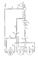
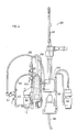
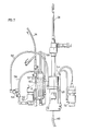
- FIG. 1 to 4 there is illustrated in Figures 1 to 4 one embodiment of the system of the invention wherein one propellant charging line is illustrated as being alternately fed with two propellant blends. It will be understood that the principles set forth herein are applicable to charging any desired number of blends to any desired number of charging lines.
- Propellant blend A is fed from a storage tank 10 by a pump 11 through line 12 to a supply manifold 14. With the downstream side of the supply manifold 14 connected to the line 12 through a connecting hose 15, as shown in Figure 1, propellant blend A passes by line 16 via a heat exchanger 18 and triplex pump 20 to a regulator 22.
- the required quantity of propellant desired to be charged to the propellant can is passed by line 24 via an accumulator 26 to a gassification device 28, details of which are described below with respect to Figure 4.
- Propellant not forwarded by line 24 to the gassification device 28 is recycled by line 30, through return manifold 32 via a connecting hose 33 and line 34 to the blend A storage tank 10.
- propellant blend B storage tank 36 connected by lines 38 and 40 respectively to the supply manifold 14 and the return manifold 32 for selective connection therethrough to feed line 16 and return line 30.
- the system also includes a scrap salvage tank 42 connected by lines 44 and 46 respectively to the supply manifold 14 and the return manifold 32 for selective connection therethrough to feed line 16 and return line 30.
- a line 48 which is joined directly to the gassification device 28 and also indirectly to the charge device through a reclaim unit 50 connected to the gassification device 28.
- valve in return line 34 is closed off at the return manifold 32 and the connecting hose 33 is bled, separated from line 34 and connected to return line 46 to the scrap salvage tank 42.
- Valves in lines 38 and 40 are opened to establish communication respectively through supply manifold 14 to line 16 and through return manifold 32 to line 30.
- blend B supply tank 36 then is turned on as is the triplex pump 20. Flow of blend B then proceeds through lines 16 and 30 through the manifold 32 to the scrap salvage tank 42, thereby clearing lines 16 and 30 of blend A. This intermediate phase of operation is seen in Figure 2.
- the triplex pump 20 is again turned off.
- the valves at the return manifold 32 are closed off and the hose 33 is bled and disconnected.
- the hose 33 then is connected to the return line 40 and the valves at the return manifold 32 are opened.
- the triplex pump 20 is turned on and the propellant blend B then recirculates between the storage tank 36.
- the gassification device 28 comprises a plurality of gassification heads 52 connected through a manifold 54 to the propellant supply line 24.
- the head 52 is connected to the manifold 54 by pipes 56 and 58 and cylinder 60.
- Pipe 56 is provided with a shut-off valve 62 adjacent the head 52.
- the pipe 56 is tapped upstream of the valve 62 and this tap is joined through shut-off valve 64 to pipe 66 which is connected to a reclaim manifold 68 which, in turn, is joined to line 48.
- valves 62 associated with each gassification head 52 is closed and each valve 64 is opened.
- the gassification device 28 then is operated in a no-can/no-fill mode, which is achieved by manually-actuating the no-can/no-fill pins on the machine as the heads rotate.
- Propellant blend B under the influence of the triplex pump 20, then passes through line 24 and, successively for each head 52, purges blend A from lines 56 and 58 and cylinder 60 through lines 66 to the reclaim manifold 68.
- the purged blend A then is expelled from the gassification device 28 through line 48 to the scrap salvage tank 42. This phase of operation is shown in Figure 5.
- valves 64 are closed and valves 62 reopened, whereupon the changeover from blend A propellant to blend B propellant is complete and normal filling operation with blend B propellant can take place, as shown in Figure 3. Operation of the gassification device reverts to that illustrated in Figure 4.
- No propellant is allowed to escape with the system described above with respect to Figures 1 to 5, and, during a changeover from one blend to another, residual propellant of one blend is vented to a scrap salvage tank 42 and not to atmosphere.
- the changeover is efficiently effected without any danger of environmental damage.
- the sump of propellant collected in the tank 42 may be processed to recover the components or disposed of.
- shut-off valves 70 and 72 Joining feed line 58 to the metering cylinder 60 are two shut-off valves 70 and 72.
- valves 62, 70 and 72 are closed and pipe 58 is disconnected from cylinder 60 at the join of the valves 70 and 72.
- the reclaim unit 50 includes a compressor 76 (see Figure 6) which pulls a vacuum on an accumulator or vacuum tank 78 for propellant. As the liquid propellant is drawn from the cylinder 60 through valve 72 and line 74 by the vacuum, it evaporates and expands in volume in the accumulator 78 and accordingly decreases the vacuum.
- the compressor 76 continues to evacuate the accumulator 78 and the vacuum eventually is reestablished for the next service requirement. As the vacuum is reestablished by the compressor 76, the propellant is compressed back to the liquid state as it is pumped via lines 80 and 48 to the scrap salvage tank 42.
- the present invention provides a novel propellant feeding system which enables changeover from one blend to another and also servicing to be effected without venting propellant to atmosphere. Modifications are possible within the scope of this invention.
Landscapes
- Chemical & Material Sciences (AREA)
- Dispersion Chemistry (AREA)
- Engineering & Computer Science (AREA)
- Mechanical Engineering (AREA)
- Filling Or Discharging Of Gas Storage Vessels (AREA)
- Containers And Packaging Bodies Having A Special Means To Remove Contents (AREA)
- Vacuum Packaging (AREA)
- Nozzles (AREA)
Applications Claiming Priority (2)
| Application Number | Priority Date | Filing Date | Title |
|---|---|---|---|
| CA565717 | 1988-05-02 | ||
| CA565717 | 1988-05-02 |
Publications (1)
| Publication Number | Publication Date |
|---|---|
| EP0340363A1 true EP0340363A1 (de) | 1989-11-08 |
Family
ID=4137955
Family Applications (1)
| Application Number | Title | Priority Date | Filing Date |
|---|---|---|---|
| EP88309783A Withdrawn EP0340363A1 (de) | 1988-05-02 | 1988-10-19 | Wiedergewinnung von Treibmittel beim Füllen von Aerosolbehältern |
Country Status (3)
| Country | Link |
|---|---|
| US (1) | US4872491A (de) |
| EP (1) | EP0340363A1 (de) |
| JP (1) | JPH0652118B2 (de) |
Cited By (1)
| Publication number | Priority date | Publication date | Assignee | Title |
|---|---|---|---|---|
| EP0633190A1 (de) * | 1993-07-07 | 1995-01-11 | Ciba-Geigy Ag | Verfahren und Vorrichtung zum Befüllen von Aerosolbehältern |
Families Citing this family (5)
| Publication number | Priority date | Publication date | Assignee | Title |
|---|---|---|---|---|
| US5345980A (en) * | 1989-09-21 | 1994-09-13 | Glaxo Group Limited | Method and apparatus an aerosol container |
| US5191919A (en) * | 1991-10-18 | 1993-03-09 | Fmc Corporation | Closed transfer means |
| USH2205H1 (en) * | 2004-07-22 | 2007-11-06 | Andersen Jason D | Method and apparatus for purging a propellant from a filling head during the filling of an aerosol container |
| US8944118B2 (en) * | 2010-05-13 | 2015-02-03 | Raffi Nalbandian | Equilibrium pressure filling method for filling pre-pressurized aerosol cans with barrier system |
| JP6516902B1 (ja) * | 2018-06-08 | 2019-05-22 | 長瀬産業株式会社 | 塗装装置及び塗装方法 |
Citations (3)
| Publication number | Priority date | Publication date | Assignee | Title |
|---|---|---|---|---|
| US2963834A (en) * | 1955-03-28 | 1960-12-13 | Kartridg Pak Co | Filling and selaing receptacles |
| US2989993A (en) * | 1958-01-09 | 1961-06-27 | Karl Kiefer Machine Company | Charging device for pressurized containers |
| EP0142346A1 (de) * | 1983-11-09 | 1985-05-22 | The BOC Group plc | Verfahren und Apparat zum Füllen von Fässern |
Family Cites Families (7)
| Publication number | Priority date | Publication date | Assignee | Title |
|---|---|---|---|---|
| US3211191A (en) * | 1955-02-04 | 1965-10-12 | Honisch Egon Johann | Apparatus for measuring a volatile liquid and for filling a container |
| US3604477A (en) * | 1968-02-13 | 1971-09-14 | Hans Grothcff | Apparatus for filing aerosol packages |
| US3797534A (en) * | 1971-02-01 | 1974-03-19 | Sprayon Prod Inc | Power operated means for filling aerosol cans |
| US3750687A (en) * | 1972-04-28 | 1973-08-07 | Texaco Inc | Method and system for transporting different types of fluid in a pipeline |
| AT366604B (de) * | 1977-02-18 | 1982-04-26 | Kronseder Hermann | Verfahren zum reinigen einer einkammer-gegendruck-fuellvorrichtung fuer flaschen od. dgl. und vorrichtung zur durchfuehrung des verfahrens |
| US4171710A (en) * | 1978-02-10 | 1979-10-23 | Boynton Edgar M | Closed pesticide mix system |
| CA1202933A (en) * | 1984-01-13 | 1986-04-08 | Gerald Doak | Sanitizing a drink supply system |
-
1988
- 1988-05-03 US US07/189,946 patent/US4872491A/en not_active Expired - Fee Related
- 1988-10-19 EP EP88309783A patent/EP0340363A1/de not_active Withdrawn
-
1989
- 1989-05-02 JP JP1112270A patent/JPH0652118B2/ja not_active Expired - Lifetime
Patent Citations (3)
| Publication number | Priority date | Publication date | Assignee | Title |
|---|---|---|---|---|
| US2963834A (en) * | 1955-03-28 | 1960-12-13 | Kartridg Pak Co | Filling and selaing receptacles |
| US2989993A (en) * | 1958-01-09 | 1961-06-27 | Karl Kiefer Machine Company | Charging device for pressurized containers |
| EP0142346A1 (de) * | 1983-11-09 | 1985-05-22 | The BOC Group plc | Verfahren und Apparat zum Füllen von Fässern |
Cited By (1)
| Publication number | Priority date | Publication date | Assignee | Title |
|---|---|---|---|---|
| EP0633190A1 (de) * | 1993-07-07 | 1995-01-11 | Ciba-Geigy Ag | Verfahren und Vorrichtung zum Befüllen von Aerosolbehältern |
Also Published As
| Publication number | Publication date |
|---|---|
| US4872491A (en) | 1989-10-10 |
| JPH0652118B2 (ja) | 1994-07-06 |
| JPH024619A (ja) | 1990-01-09 |
Similar Documents
| Publication | Publication Date | Title |
|---|---|---|
| US9651284B2 (en) | Service device for vehicle air conditioning systems, and method for operating same, in particular for the self-cleaning type | |
| US9834062B2 (en) | Method for maintaining a vehicle air conditioning unit and service apparatus therefor | |
| US5884675A (en) | Cascade system for fueling compressed natural gas | |
| EP1839975B1 (de) | Wasserstoffverdichtersystem | |
| US5694985A (en) | System and method for compressing natural gas and for refueling motor vehicles | |
| US8978715B2 (en) | Method for filling a tank with pressurized gas | |
| EP4160077A1 (de) | System und verfahren zur rückgewinnung von gasförmigem wasserstoff in einer wasserstofftankstelle | |
| US5095713A (en) | Refrigerant handling system and method with multiple refrigerant capability | |
| WO2003019016A1 (en) | Method and apparatus for filling a storage vessel with compressed gas | |
| US4872491A (en) | Recovery of propellant from aerosol can filling operation | |
| JP2022096650A (ja) | アンモニア分解ユニット一体型水素供給ステーション | |
| US4149574A (en) | Apparatus for filling a hollow and closed system provided with only one filling aperture | |
| CN217208898U (zh) | 一种制氢加氢一体站控制系统 | |
| WO2004091970A2 (en) | Vessel fueling method and apparatus | |
| CN212840738U (zh) | 一种多功能气体增压机 | |
| GB2081122A (en) | Sludge dewatering plant | |
| JPH10187249A (ja) | 試験装置の試験液中に所定の定圧を発生させる方法 | |
| CN111692518B (zh) | 一种lng加气站用柱塞泵引流方法及设备 | |
| CN207471116U (zh) | 一种压差式lng加注站加注系统 | |
| US5537835A (en) | Refrigerant recovery systems employing series/parallel pumps | |
| CN202834741U (zh) | 一种钢瓶灌装设备上连通多个泵的装置 | |
| EP0823968A1 (de) | Hochdruckgasversorgung | |
| CN211575627U (zh) | 汽车空调制冷系统清洗机 | |
| US5067325A (en) | Method and arrangement for pumping refrigerants | |
| CN221121873U (zh) | 气体充装装置 |
Legal Events
| Date | Code | Title | Description |
|---|---|---|---|
| PUAI | Public reference made under article 153(3) epc to a published international application that has entered the european phase |
Free format text: ORIGINAL CODE: 0009012 |
|
| AK | Designated contracting states |
Kind code of ref document: A1 Designated state(s): AT BE CH DE ES FR GB GR IT LI LU NL SE |
|
| STAA | Information on the status of an ep patent application or granted ep patent |
Free format text: STATUS: THE APPLICATION IS DEEMED TO BE WITHDRAWN |
|
| 18D | Application deemed to be withdrawn |
Effective date: 19900509 |