EP0340510A2 - Installation de broyage à courant d'air - Google Patents
Installation de broyage à courant d'air Download PDFInfo
- Publication number
- EP0340510A2 EP0340510A2 EP89106732A EP89106732A EP0340510A2 EP 0340510 A2 EP0340510 A2 EP 0340510A2 EP 89106732 A EP89106732 A EP 89106732A EP 89106732 A EP89106732 A EP 89106732A EP 0340510 A2 EP0340510 A2 EP 0340510A2
- Authority
- EP
- European Patent Office
- Prior art keywords
- grinding
- roller
- bowl
- airflow
- rollers
- Prior art date
- Legal status (The legal status is an assumption and is not a legal conclusion. Google has not performed a legal analysis and makes no representation as to the accuracy of the status listed.)
- Withdrawn
Links
- 239000000463 material Substances 0.000 claims abstract description 17
- 239000000203 mixture Substances 0.000 claims abstract description 9
- 230000005540 biological transmission Effects 0.000 claims 1
- 238000007789 sealing Methods 0.000 claims 1
- 230000000694 effects Effects 0.000 abstract description 5
- 239000000428 dust Substances 0.000 description 15
- 230000008878 coupling Effects 0.000 description 6
- 238000010168 coupling process Methods 0.000 description 6
- 238000005859 coupling reaction Methods 0.000 description 6
- 230000000712 assembly Effects 0.000 description 5
- 238000000429 assembly Methods 0.000 description 5
- 230000000903 blocking effect Effects 0.000 description 3
- 239000007788 liquid Substances 0.000 description 2
- 239000002245 particle Substances 0.000 description 2
- 238000009825 accumulation Methods 0.000 description 1
- 230000002411 adverse Effects 0.000 description 1
- 230000015572 biosynthetic process Effects 0.000 description 1
- 239000004568 cement Substances 0.000 description 1
- 239000003245 coal Substances 0.000 description 1
- 230000005484 gravity Effects 0.000 description 1
- 239000000256 polyoxyethylene sorbitan monolaurate Substances 0.000 description 1
- 230000002035 prolonged effect Effects 0.000 description 1
- 239000002994 raw material Substances 0.000 description 1
- 230000000717 retained effect Effects 0.000 description 1
- 230000000630 rising effect Effects 0.000 description 1
Images


Classifications
-
- B—PERFORMING OPERATIONS; TRANSPORTING
- B02—CRUSHING, PULVERISING, OR DISINTEGRATING; PREPARATORY TREATMENT OF GRAIN FOR MILLING
- B02C—CRUSHING, PULVERISING, OR DISINTEGRATING IN GENERAL; MILLING GRAIN
- B02C15/00—Disintegrating by milling members in the form of rollers or balls co-operating with rings or discs
- B02C15/16—Disintegrating by milling members in the form of rollers or balls co-operating with rings or discs with milling members essentially having different peripheral speeds and in the form of a hollow cylinder or cone and an internal roller or cone
-
- B—PERFORMING OPERATIONS; TRANSPORTING
- B02—CRUSHING, PULVERISING, OR DISINTEGRATING; PREPARATORY TREATMENT OF GRAIN FOR MILLING
- B02C—CRUSHING, PULVERISING, OR DISINTEGRATING IN GENERAL; MILLING GRAIN
- B02C15/00—Disintegrating by milling members in the form of rollers or balls co-operating with rings or discs
- B02C15/04—Mills with pressed pendularly-mounted rollers, e.g. spring pressed
-
- B—PERFORMING OPERATIONS; TRANSPORTING
- B02—CRUSHING, PULVERISING, OR DISINTEGRATING; PREPARATORY TREATMENT OF GRAIN FOR MILLING
- B02C—CRUSHING, PULVERISING, OR DISINTEGRATING IN GENERAL; MILLING GRAIN
- B02C15/00—Disintegrating by milling members in the form of rollers or balls co-operating with rings or discs
- B02C2015/002—Disintegrating by milling members in the form of rollers or balls co-operating with rings or discs combined with a classifier
Definitions
- the invention relates to an airflow grinding system according to the preamble of claim 1.
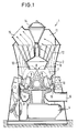
- Such an airflow grinding plant is e.g. known from DE-PS 20 19 005 and EP 0 173 065 A2 and shown in Fig. 1.
- the airflow grinding system 1 which is on a foundation, is usually enclosed in an airtight manner by a housing 2.
- the grinding plant consists of a lower roller mill, above which an integrated classifier 11 is installed in the upper area.
- the grinding bowl 3 is set in rotation via a drive 4.
- the regrind fed from above or from the side onto the grinding bowl 3 is comminuted between the resiliently pressed grinding rollers 9 and the grinding bowl 3.
- the grinding rollers 9 do not have a separate drive, but are set in rotation solely by the frictional connection between grinding bowl 3 or the grinding material present between them and the grinding bowl.
- the air flowing in via the feed channel 6 and the guide vane ring 16 conveys the mixture of finished and coarse material which is thrown off the grinding bowl 3 after being rolled over by the grinding rollers 9 Grain upwards in the area of the classifier 11. Due to the rotor 12, which is driven by its own rotor drive 14, oversize is rejected in accordance with the rotation and the rising volume flow of the air dust mixture 13, so that this, together with a partial air flow, is returned to the grinding bowl 3 in the area of a so-called vertebral sink 8 falls back. The fines or finished goods, on the other hand, leave the classifier 11 via the fines outlet 15.
- FIG. 1 These normally occurring flow conditions of the air / dust mixture are shown in FIG. 1 with broken lines as current threads.
- a vertebral sink 8 forms below the classifying rotor 12 in the center of the roller mill, wherein not only ground material particles, but also air or gas are almost returned downwards to the grinding bowl 3 in the circuit.
- This air / dust mixture is drawn in by the grinding rollers 3 and rolled over. The air naturally escapes.
- the oversize rejected by the classifier 11 is also much finer. Since the buoyancy of the finest semolina in the air is higher than in the case of coarse semolina, the proportion of gravity that returns the oversize particles to the grinding bowl 3 also becomes lower. Ultimately, this means that an extremely highly ventilated "dust cloud” falls back on the grinding bowl or is returned. This cloud of dust can be compared to a liquid from a physical point of view due to its very low internal friction.
- the invention is therefore based on the object of constructing a generic airflow grinding system in such a way that a high degree of efficiency with regard to the mill throughput is achieved, in particular when a high degree of fineness of the grinding material is required, where possible the functional sequence becomes more uniform, so that impact loads during power consumption or in mechanical terms are largely reduced.
- the grinding rollers are therefore forcibly driven by appropriately separately assigned drive devices, such as e.g. Electric motors driven at a speed that corresponds at least to the theoretical speed with a frictional connection between the grinding bowl and the corresponding grinding roller.
- This theoretical speed is understood to mean the speed that would occur if the grinding rollers were to rotate continuously as compared to a grinding bed existing in the prior art.
- the speed of the grinding rollers is advantageously chosen to be somewhat greater than the aforementioned theoretical speed. This ensures that there is no sliding or sliding or blocking of the grinding rollers with respect to the grinding bed or the grinding bowl, so that effective grinding of the material to be ground is actually achieved.
- This speed of the grinding rollers should, if possible, be infinitely adjustable so that an adjustment or regulation according to the fineness of the desired material to be ground, the size of the grinding bed, the load condition or the running behavior of the roller mill is possible.
- the forcibly applied speed of the grinding rollers, with which a dust wave forming in front of the roller can be prevented in any case, is therefore an essential feature of the invention.
- the drive torque T per grinding roller should be designed so that the drive torque T to be installed for a grinding roller is less than or equal to a value that results from the quotient of the torque of the grinding bowl T grinding bowl and the number of grinding rolls.
- the drive devices provided for the separate drive of the respective grinding roller are of any type, e.g. electrically, mechanically, hydraulically, expediently installed on the side remote from the grinding rollers.
- Drive devices such as electric motors, which can be uncoupled from the housing of the grinding system, are particularly suitable.
- the drive devices can also be stored and held separately from the housing. It is essential that the output shaft of the drive device can be decoupled from the drive shaft for the grinding rollers.
- the grinding roller is rotatably mounted in the rocker arm of the respective roller unit with a roller shaft rigidly attached to it.
- the drive device is then expediently attached to the rocker arm, so that rocking movements of the roller unit do not require separate compensation devices due to a different grinding bed height.
- the second alternative of the drive implementation provides for a stationary hollow axis arranged in the rocker arm.
- the grinding roller is also held in rotation at the inner end of the hollow axis via roller bearings, for example axial and radial bearings.
- the actual drive takes place via a drive shaft which is guided through the hollow axis and which applies the required torque to the grinding roller on the roller side via a closing device.
- This drive shaft is connected to the drive device at the other end, radial and axial adjustability, in particular gimbal type, of the entire shaft being possible via intermediate members.
- An electric motor provided, for example, as a drive device can in this case be fixed directly to the rocker arm or attached to the outside of the housing in such a way that it can be disconnected.
- a spring device which is at least in engagement with the rocking lever and is supported on a stationary part of the grinding system, is provided for applying the contact pressure of the roller against the ground material.
- the respective grinding roller is also driven according to the invention in addition to driving the grinding bowl 3.
- the corresponding speed and the torque are coordinated so that an independent rotation of the corresponding grinding roller occurs in front of the roller without the formation of a material material bow wave.
- the direction of rotation between the grinding roller and grinding bowl at the grinding gap or regrind bed is directed in the same direction.
- the exemplary embodiment according to FIG. 2 relates schematically to a first alternative for driving a grinding roller 20.
- the roller unit consisting of grinding roller 20 and rocking lever 25 is arranged so as to be pivotable about a rocker arm joint 34 on the housing or on its own foundation block on a bearing housing 35.
- the basic principle of this drive alternative is to provide a hollow shaft 23 rigidly fixed in the bushing 27 of the rocker arm 25, for example via a clamping device 36.
- the grinding roller is rotatably mounted on this hollow shaft 23 on the roll side, in FIG. 2 at the right end of the hollow shaft, via radial bearings 32 and angular bearings 33.
- the grinding roller 20, which in the example consists of the radially inner roller body 21 and the outer roller shell 22 forming a truncated cone, is driven with the appropriate torque via a drive shaft 24 which is guided in the hollow shaft 23 and is optionally supported.
- the roller shell 22 is fixed rigidly, but replaceably, on the roller body 21 via a bolt device 48 and a clamping ring 49.
- the roller unit shown in FIG. 2 is closed off by a cap-like closure device 44.
- This termination device 44 and its fastenings 50 serve primarily to transmit the drive torque from the inner drive shaft 24 via a coupling member 45 and its rigid connection 46 to the actual grinding roller.
- a dust-tight seal for the inner shafts and a counterbearing for the inclined bearing 33 is achieved by this termination device 44.
- the inner drive shaft 24 is connected via a coupling shaft 43 to the output shaft 42 of a schematically indicated motor 26, e.g. an electric motor, in connection.
- This motor 26 is held by a fastening 41 on an end plate 39 which is fixed on the rocker arm 25.
- the output shaft 42 of the motor 26 projects into the hollow axis 23 through a corresponding opening 40.
- the shaft members are designed so that there is an axial adjustment in the direction of the longitudinal axis of the hollow axis, but also a radial adjustment. Universal joints or universal joints are also possible as coupling links.
- roller unit is acted upon by a pressure spring 29 via a flange 28, this spring 29 being supported as a counter bearing in relation to a stationary part 30.
- both the grinding bowl 3 rotates about its axis of rotation 47 and - independently of it and designed with its own drive - the grinding roller unit, so that adverse effects, as set out above, are prevented by the separate drive of the grinding roller .
- the dimensioning of the bore 31 of the hollow shaft 23 is based on the outer circumference of the coupling members or the drive shaft 24 and on the other hand on the required stability for taking up the roll load and roll rotation.
- a roller shaft 56 connected to the grinding roller 55 is provided.
- This roller shaft is e.g. via bearings 53 rotatably mounted to absorb axial and radial forces in the bushing 52 of the rocker arm.
- the drive takes place here via a drive device 58 with a corresponding drive shaft 57.
- the rocker arm 25 is mounted in a manner similar to the aforementioned example via a rocker arm joint 34 relative to a bearing housing 35.
- the rocking lever 25 enables the compensating movements of the grinding roller 55 with respect to the grinding bowl 3 rotating about the axis 47.
- the rocking lever also serves to pivot the entire roller unit out of the corresponding housing of the grinding system.
- a pressure spring 29 supported on a stationary part 30 of the housing acts, as in the previous example, on the grinding roller 55 via a flange 28 and the rocker arm 25.
- the drive device 58 is fastened to the rocker arm 25 via a motor mount 54 in the example according to FIG. 3.
- the bearings of the roller shaft 56 are encapsulated, if possible, just like the actual drive device 58 in a dust-tight manner with respect to the interior 7 of the grinding system.
- the roller-side closure is formed by a rounded roller cap 69.
- FIGS. 2 and 3 could be used, for example, in a mill 1 according to FIG. 1 operated in a vacuum.
- FIG. 4 shows an airflow grinding system according to the invention in elevation, assemblies which largely correspond to the prior art being identified by the same reference numerals as in FIG. 1.
- the airflow grinding system 60 shown in FIG. 4 has a grinding bowl 61 in the area of the roller mill, which has a dome-like central elevation 62 for distributing the supplied or circulating material to be ground onto the grinding path.
- the millbase is supplied via a material feed channel 64 which runs centrally through the classifier 11 from top to bottom.
- a hollow rotor drive shaft 65 is rotatably provided around this channel for driving the rotor 12.
- the drive device of the grinding roller 20 shown on the left corresponds approximately to the alternative shown in FIG. 2, the torque being applied to the grinding roller 20 via a drive shaft 24 running in a hollow shaft.
- the drive shaft 42 protrudes through an opening 63 in the outer housing 2 of the grinding system.
- the passage openings or bearings for the drive shafts are designed to be gas and dust-tight, which is not reflected in the schematic drawing.
- the separate drive of the individual grinding rollers 20 prevents the material to be backed up in front of the rollers, thereby avoiding sliding or blocking effects which cause the roller mill to run unevenly and also bring about greater wear and tear.
- the drive units can be designed for a low maximum output, since impact stresses, as can still occur in the prior art, are largely prevented.
- the throughput performance even with a regrind with high required fineness can be significantly improved in this way.
Landscapes
- Engineering & Computer Science (AREA)
- Food Science & Technology (AREA)
- Crushing And Grinding (AREA)
Applications Claiming Priority (2)
| Application Number | Priority Date | Filing Date | Title |
|---|---|---|---|
| DE3815218 | 1988-05-04 | ||
| DE3815218A DE3815218A1 (de) | 1988-05-04 | 1988-05-04 | Luftstrom-mahlanlage |
Publications (2)
| Publication Number | Publication Date |
|---|---|
| EP0340510A2 true EP0340510A2 (fr) | 1989-11-08 |
| EP0340510A3 EP0340510A3 (fr) | 1990-03-07 |
Family
ID=6353634
Family Applications (1)
| Application Number | Title | Priority Date | Filing Date |
|---|---|---|---|
| EP89106732A Withdrawn EP0340510A3 (fr) | 1988-05-04 | 1989-04-14 | Installation de broyage à courant d'air |
Country Status (5)
| Country | Link |
|---|---|
| EP (1) | EP0340510A3 (fr) |
| JP (1) | JPH0710357B2 (fr) |
| DE (1) | DE3815218A1 (fr) |
| DK (1) | DK183189A (fr) |
| ZA (1) | ZA893019B (fr) |
Cited By (4)
| Publication number | Priority date | Publication date | Assignee | Title |
|---|---|---|---|---|
| DE3938320A1 (de) * | 1989-11-17 | 1991-05-23 | Krupp Polysius Ag | Waelzmuehle |
| DE102010056044A1 (de) * | 2010-12-23 | 2012-06-28 | Keller Hcw Gmbh | Läufermantel und Felge für einen Kollerläufer, Kollerläufer sowie Verfahren zum Herstellen des Kollerläufers |
| CN108698049A (zh) * | 2016-02-08 | 2018-10-23 | 德国莱歇公司 | 研磨辊装置 |
| CN118543425A (zh) * | 2024-06-15 | 2024-08-27 | 唐县冀东水泥有限责任公司 | 高细水泥粉磨装置 |
Families Citing this family (13)
| Publication number | Priority date | Publication date | Assignee | Title |
|---|---|---|---|---|
| DE102007006092A1 (de) * | 2007-02-07 | 2008-08-14 | Polysius Ag | Verfahren zur Zerkleinerung von Mahlgut mit einer Rollenmühle |
| DE102008036784C5 (de) * | 2008-08-07 | 2013-06-20 | Thyssenkrupp Polysius Ag | Rollenmühle und Verfahren zur Zerkleinerung von Mahlgut |
| DE102008039542B4 (de) * | 2008-08-25 | 2010-04-15 | Polysius Ag | Rollenmühle |
| DE102008039543B4 (de) * | 2008-08-25 | 2010-05-12 | Polysius Ag | Rollenmühle |
| DE102008039539B4 (de) * | 2008-08-25 | 2010-08-26 | Polysius Ag | Rollenmühle |
| DE102009012353C5 (de) * | 2009-03-09 | 2013-08-22 | ThyssenKrupp Resource Technologies AG | Rollenmühle |
| RU2427425C2 (ru) * | 2009-08-18 | 2011-08-27 | Бобин Вячеслав Александрович | Гироскопический измельчитель сухой породы по фракциям |
| RU2429912C2 (ru) * | 2009-08-18 | 2011-09-27 | Бобин Вячеслав Александрович | Гироскопический измельчитель с центральной загрузкой породы |
| WO2013046422A1 (fr) * | 2011-09-30 | 2013-04-04 | 三菱重工業株式会社 | Dispositif de broyage de biomasse et système de combustion mixte de biomasse et de charbon |
| CN104329660A (zh) * | 2011-09-30 | 2015-02-04 | 三菱重工业株式会社 | 生物质粉碎装置及生物质/煤混烧系统 |
| JP6469343B2 (ja) | 2013-12-13 | 2019-02-13 | 三菱日立パワーシステムズ株式会社 | 固体燃料粉砕装置および固体燃料粉砕装置の製造方法 |
| DK2999542T3 (da) * | 2014-10-31 | 2017-11-13 | Loesche Gmbh | Formalingsvalse |
| CN117861828B (zh) * | 2024-03-11 | 2024-05-31 | 山东红点新材料有限公司 | 用于等静压石墨骨料焦炭磨粉的超微粉碎机 |
Family Cites Families (6)
| Publication number | Priority date | Publication date | Assignee | Title |
|---|---|---|---|---|
| DE636062C (de) * | 1933-05-03 | 1936-10-01 | Ernst Curt Loesche | Mahlverfahren |
| JPS58159854A (ja) * | 1982-03-16 | 1983-09-22 | 株式会社神戸製鋼所 | 竪型ロ−ラミルのロ−ラ駆動方法及びその装置 |
| JPS60197248A (ja) * | 1984-03-21 | 1985-10-05 | 川崎重工業株式会社 | 竪型ロ−ラミルのロ−ラ装置 |
| JPS62109743U (fr) * | 1985-12-27 | 1987-07-13 | ||
| DE3602932A1 (de) * | 1986-01-31 | 1987-08-06 | Kloeckner Humboldt Deutz Ag | Verfahren und vorrichtung zum zerkleinern von feststoffen |
| JPS6452551U (fr) * | 1987-09-28 | 1989-03-31 |
-
1988
- 1988-05-04 DE DE3815218A patent/DE3815218A1/de not_active Ceased
-
1989
- 1989-04-14 EP EP89106732A patent/EP0340510A3/fr not_active Withdrawn
- 1989-04-14 DK DK183189A patent/DK183189A/da not_active Application Discontinuation
- 1989-04-25 ZA ZA893019A patent/ZA893019B/xx unknown
- 1989-05-02 JP JP1113541A patent/JPH0710357B2/ja not_active Expired - Fee Related
Cited By (5)
| Publication number | Priority date | Publication date | Assignee | Title |
|---|---|---|---|---|
| DE3938320A1 (de) * | 1989-11-17 | 1991-05-23 | Krupp Polysius Ag | Waelzmuehle |
| DE102010056044A1 (de) * | 2010-12-23 | 2012-06-28 | Keller Hcw Gmbh | Läufermantel und Felge für einen Kollerläufer, Kollerläufer sowie Verfahren zum Herstellen des Kollerläufers |
| CN108698049A (zh) * | 2016-02-08 | 2018-10-23 | 德国莱歇公司 | 研磨辊装置 |
| CN108698049B (zh) * | 2016-02-08 | 2020-09-22 | 德国莱歇公司 | 研磨辊装置 |
| CN118543425A (zh) * | 2024-06-15 | 2024-08-27 | 唐县冀东水泥有限责任公司 | 高细水泥粉磨装置 |
Also Published As
| Publication number | Publication date |
|---|---|
| JPH0263559A (ja) | 1990-03-02 |
| DK183189D0 (da) | 1989-04-14 |
| EP0340510A3 (fr) | 1990-03-07 |
| JPH0710357B2 (ja) | 1995-02-08 |
| ZA893019B (en) | 1989-12-27 |
| DK183189A (da) | 1989-11-05 |
| DE3815218A1 (de) | 1989-11-16 |
Similar Documents
| Publication | Publication Date | Title |
|---|---|---|
| EP0340510A2 (fr) | Installation de broyage à courant d'air | |
| EP0357762B1 (fr) | Procede et dispositif pour moudre et separer le grain | |
| EP0406644B1 (fr) | Broyeur à rouleaux à courant d'air | |
| EP0615483B1 (fr) | Meuleuse a disque a excentrique | |
| DE2616155A1 (de) | Nassmahlvorrichtung | |
| EP1239966A1 (fr) | Separateur de broyeur | |
| DE3490332T1 (de) | Walzenmühle | |
| EP2482987B1 (fr) | Procédé et dispositif de fragmentation de matière minérale | |
| EP1214155B1 (fr) | Procede et separateur a air servant a separer de la matiere de chargement fractionnee | |
| EP0973612A1 (fr) | Dispositif pour regler l'espace entre des cylindres de broyage | |
| EP0856357B1 (fr) | Concasseur à percussion | |
| DE3602932A1 (de) | Verfahren und vorrichtung zum zerkleinern von feststoffen | |
| DE60123416T2 (de) | Refiner | |
| EP0294609A2 (fr) | Broyeur à rouleaux | |
| DE69504763T2 (de) | Verbesserter Kollergang für Ton oder Zuschlagstoffe im allgemeinen | |
| DE4140549A1 (de) | Walzenmuehle | |
| DE29616319U1 (de) | Walzenbrecher | |
| DE3220092A1 (de) | Dispergiervorrichtung | |
| DE1214516B (de) | Ruehrwerksmuehle zum kontinuierlichen Feinstzerkleinern und Dispergieren von Feststoffen | |
| EP0902189B1 (fr) | Pompe d'alimentation | |
| DE10206709A1 (de) | Backenbrecher | |
| DE102023106730A1 (de) | Kegelbrecher mit windschief ausgerichteter Achse | |
| DE2547709A1 (de) | Vertikalachsiger umluft-windsichter | |
| DE175299C (fr) | ||
| DE903779C (de) | Tellerbrecher |
Legal Events
| Date | Code | Title | Description |
|---|---|---|---|
| PUAI | Public reference made under article 153(3) epc to a published international application that has entered the european phase |
Free format text: ORIGINAL CODE: 0009012 |
|
| AK | Designated contracting states |
Kind code of ref document: A2 Designated state(s): DE FR GB |
|
| PUAL | Search report despatched |
Free format text: ORIGINAL CODE: 0009013 |
|
| AK | Designated contracting states |
Kind code of ref document: A3 Designated state(s): DE FR GB |
|
| STAA | Information on the status of an ep patent application or granted ep patent |
Free format text: STATUS: THE APPLICATION IS DEEMED TO BE WITHDRAWN |
|
| 18D | Application deemed to be withdrawn |
Effective date: 19900908 |