EP0340541A1 - Fahrzeughinterradaufhängung mit Rollbeeinflussung beim Bremsen und Beschleunigen - Google Patents
Fahrzeughinterradaufhängung mit Rollbeeinflussung beim Bremsen und Beschleunigen Download PDFInfo
- Publication number
- EP0340541A1 EP0340541A1 EP89107079A EP89107079A EP0340541A1 EP 0340541 A1 EP0340541 A1 EP 0340541A1 EP 89107079 A EP89107079 A EP 89107079A EP 89107079 A EP89107079 A EP 89107079A EP 0340541 A1 EP0340541 A1 EP 0340541A1
- Authority
- EP
- European Patent Office
- Prior art keywords
- point
- vehicle body
- wheel
- supporting member
- wheel supporting
- Prior art date
- Legal status (The legal status is an assumption and is not a legal conclusion. Google has not performed a legal analysis and makes no representation as to the accuracy of the status listed.)
- Granted
Links
Images


Classifications
-
- B—PERFORMING OPERATIONS; TRANSPORTING
- B60—VEHICLES IN GENERAL
- B60G—VEHICLE SUSPENSION ARRANGEMENTS
- B60G3/00—Resilient suspensions for a single wheel
- B60G3/18—Resilient suspensions for a single wheel with two or more pivoted arms, e.g. parallelogram
Definitions
- the present invention relates to a rear suspension of a vehicle such as an automobile, and more particularly, to a rear suspension for mounting a rear wheel to a vehicle body in a manner of transmitting driving and braking forces therebetween while allowing bounding and rebounding of the rear wheel relative to the vehicle body.
- the conventional wishbone type rear suspension is, if the inclination is appropriately designed, able to provide a constant anti-squatting effect and a constant anti-nose diving effect regardless of the bounding and rebounding of the wheel relative to the vehicle body. Therefore, however, this type of rear suspension has no effect of suppressing the rolling of the vehicle body in turning of the vehicle, regardless of driving or braking, although it has therefore no adverse effect on it.
- the conventional trailing arm type rear suspension has a desirable effect of suppressing the rolling of the vehicle body in turning of the vehicle under braking, although too much suppression of the rolling in turning under braking has an adverse effect of increasing the probability of vehicle spinning.
- the rear suspension of this type has an adverse effect on the rolling of the vehicle body in turning of the vehicle under driving, because the balance of the driving forces applied from a pair of rear wheels to the vehicle body always acts to promote the rolling of the vehicle body along with increase of the rolling.
- the present invention is based upon the above-mentioned geometric analysis of the prior art vehicle suspension with a certain idea of effectively utilizing the driving and braking force to accomplish a desirable control of the rolling of the vehicle body in turning of the vehicle.
- a rear suspension of a vehicle for mounting a rear wheel to a vehicle body in a manner of transmitting driving and braking forces therebetween while allowing bounding and rebounding of the rear wheel relative to the vehicle body comprising: a wheel supporting member for supporting said rear wheel to be rotatable about a center of rotation, and a plurality of links each being pivotably connected at a first end thereof with said vehicle body at a determinate point thereof and at a second end thereof with said wheel supporting member at a determinate point thereof so as thereby in combination to define a first trace of movement of said center of rotation of said rear wheel relative to said vehicle body and a second trace of movement of a momentary ground contact point of said rear wheel relative to said vehicle body in the bounding and the rebounding of said rear wheel relative to said vehicle body, wherein an effective length of each said link between said first and second ends thereof and said determinate points in said vehicle body and in said wheel supporting member corresponding to each said link are so determined that
- said links may comprise an upper A-type arm pivotably connected at two food ends thereof with the vehicle body at a first and a second point thereof to define a first pivot axis passing through said first and second points and at an apex end thereof with said wheel supporting member, and a lower A-type arm pivotably connected at two foot ends thereof with the vehicle body at a third and a fourth point thereof to define a second pivot axis passing through said third and fourth points and at an apex end thereof with said wheel supporting member, said first pivot axis being inclined to descend in the front and to ascend in the rear as viewed in said side view, said second pivot axis being inclined to ascend in the front and to descend in the rear as viewed in said side view.
- the ratio L1/L2 may desirably be substantially equal to the ratio r1/r2.
- said links may comprise a first substantially I-type link pivotably connected at an inner end thereof with the vehicle body at a first point thereof and at an outer end thereof with said wheel supporting member at a first point thereof, a second substantially I-type link pivotably connected at an inner end thereof with the vehicle body at a second point thereof positioned on the rear side of said first point thereof and at an outer end thereof with said wheel supporting a member at a second point thereof positioned on the rear side of said first point thereof, a third substantially I-type link pivotably connected at an inner end thereof with the vehicle body at a third point thereof positioned under said first point thereof and at an outer end thereof with said wheel supporting member at a third point thereof positioned under said first point thereof, a fourth substantially I-type link pivotably connected at an inner end thereof with the vehicle body at a fourth point thereof positioned under said second point thereof and on the rear side of said third point thereof and at an outer end thereof with said wheel supporting member at a fourth point thereof positioned under said second point thereof and on the rear side of said rear side of
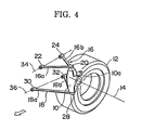
- the rear suspension of a vehicle is constructed in the form of a double wishbone type suspension employing an A-type upper arm 16 and an A-type lower arm 18 which in combination support a wheel supporting member 10 having a bearing construction for supporting a axle (not shown) to be rotatable about an axis of rotation 14 of a wheel 12 only shown by a tire portion thereof.
- the A-type upper arm 16 has two leg portions 16a and 16b and is pivotably connected with the wheel supporting member 10 at its apex end via a ball joint 20 and with a vehicle body 26 (Fig. 5) at its two foot ends via pivot joints 22 and 24 arranged to define a pivot axis 34.
- a phantom line 38 is a trace of movement of the ball joint 20 according to up and down swinging of the upper arm 16 due to bounding and rebounding of the wheel
- a phantom line 40 is a trace of movement of the ball joint 28 according to up and down swinging of the lower arm 18 due to bounding and rebounding of the wheel.
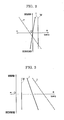
- the inclination of the trace of movement 38 from a standard point "s" corresponding to no bounding and no rebounding of the wheel upward and forward to a point of bounding "b" corresponding a bounding of the wheel and downward and rearward to a point of rebounding "r” corresponding to a rebounding of the wheel is generated by inclining the pivot axis 34 to descend in the front and to ascend in the rear as seen in a side of the vehicle like Fig. 6.
- the inclination of the trace of movement 40 from a standard point "s" corresponding to no bounding and no rebounding of the wheel upward and rearward to a point of bounding "b" corresponding a bounding of the wheel and downward and forward to a point of rebounding "r” corresponding to a rebounding of the wheel is generated by inclining the pivot axis 36 to ascend in the front and to descend in the rear as in a side of the vehicle like Fig. 6.
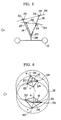
- the wheel supporting member 10 is correspondingly modified to have two pivot points 66 and 68 for pivoting connection with two foot ends of two leg portions 62a and 62b of the inverse A-type arm 62, and a pivot point 72 for pivoting connection with an outside end of the I-type arm 64.
- the apex portion of the inverse A-type arm 62 is pivotably connected with the vehicle body 26 at a pivot point 70, whereas the inside end of the I-type arm 64 is pivotably connected with the vehicle body at a pivot point 74, thereby defining a pivot axis 36 corresponding to the same numbered pivot axis 36 in the embodiment shown in Figs.
- the suspension of this embodiment is applicable to a steerable rear wheel so that the wheel supporting member 10 is turned about the pivot axis 76 serving as a steering axis like to so-called king pin.
- the pivot point 66 Since the pivot point 66 is positioned closer to the center of bounding and rebounding than the pivot point 72, the amplitude of movement l1 of the pivot 66 and is smaller than the amplitude of movement l2 of the pivot point 72.
- the cornering power of the rear wheel lowers, thereby causing a loss of the steering ability of the vehicle, whereas, if the toeing of the rear wheel changes so much toward toe-in direction as shown by a curve 88 in Fig. 11 according to the bounding and rebounding of the wheel, a running instability such as the bump steer is apt to occur.
- the effective length L1 of the leg portion 62a is determined relative to the effective length L2 of the I-type arm 64 so as to satisfy the above-mentioned condition or to be slightly shorter than that so that the change of toeing of the wheel is within such a range as indicated by a hatched area 92.
- a rear suspension of a vehicle such as an automobile having a plurality of links pivotably connected between the vehicle body and a wheel supporting member to transmit driving and braking forces therebetween while allowing bounding and rebounding movement of the wheel supporting member relative to the vehicle body, wherein the links are arranged to specify a first trace of movement of a center of rotation of the wheel and a second trace of movement of a momentary ground contact point on the wheel according to bounding and rebounding of the wheel so that, as seen in a side view of the vehicle, the point of intersection between a normal line drawn to the first trace of movement and a normal line drawn to the second trace of movement shifts from its standard position corresponding no bounding and no rebounding of the wheel forward and upward along with bounding of the wheel and rearward and downward along with rebounding of the wheel.
Landscapes
- Engineering & Computer Science (AREA)
- Mechanical Engineering (AREA)
- Vehicle Body Suspensions (AREA)
Applications Claiming Priority (2)
| Application Number | Priority Date | Filing Date | Title |
|---|---|---|---|
| JP95997/88 | 1988-04-19 | ||
| JP63095997A JP2569714B2 (ja) | 1988-04-19 | 1988-04-19 | 車輌用リヤサスペンション |
Publications (2)
| Publication Number | Publication Date |
|---|---|
| EP0340541A1 true EP0340541A1 (de) | 1989-11-08 |
| EP0340541B1 EP0340541B1 (de) | 1992-10-28 |
Family
ID=14152744
Family Applications (1)
| Application Number | Title | Priority Date | Filing Date |
|---|---|---|---|
| EP89107079A Expired EP0340541B1 (de) | 1988-04-19 | 1989-04-19 | Fahrzeughinterradaufhängung mit Rollbeeinflussung beim Bremsen und Beschleunigen |
Country Status (4)
| Country | Link |
|---|---|
| US (1) | US4925207A (de) |
| EP (1) | EP0340541B1 (de) |
| JP (1) | JP2569714B2 (de) |
| DE (1) | DE68903295T2 (de) |
Cited By (2)
| Publication number | Priority date | Publication date | Assignee | Title |
|---|---|---|---|---|
| GB2277303A (en) * | 1993-03-26 | 1994-10-26 | Honda Motor Co Ltd | Multi-link type suspension system |
| EP1440826A3 (de) * | 2003-01-21 | 2005-02-02 | Bose Corporation | Aktives Fahrwerksystem eines Fahrzeugs |
Families Citing this family (6)
| Publication number | Priority date | Publication date | Assignee | Title |
|---|---|---|---|---|
| US5845926A (en) * | 1997-01-21 | 1998-12-08 | Ford Global Technologies, Inc. | Independent suspension apparatus for a wheeled vehicle |
| US6109631A (en) * | 1998-04-30 | 2000-08-29 | Ford Global Technologies, Inc. | Independent suspension apparatus for a wheeled vehicle |
| US7004484B1 (en) | 2001-08-17 | 2006-02-28 | Polaris Industries Inc. | Providing an enhanced ATV riding experience |
| US6942050B1 (en) | 2004-04-28 | 2005-09-13 | Polaris Industries Inc. | Snowmobile front suspension system and method |
| US7571918B2 (en) * | 2006-03-31 | 2009-08-11 | Honda Motor Company, Ltd. | Suspension arm for a vehicle |
| US8037961B2 (en) * | 2007-01-24 | 2011-10-18 | Bombardier Recreational Products Inc. | Snowmobile front suspension |
Citations (5)
| Publication number | Priority date | Publication date | Assignee | Title |
|---|---|---|---|---|
| US3189118A (en) * | 1960-12-22 | 1965-06-15 | Ford Motor Co | Vehicle rear wheel suspension |
| DE1430770A1 (de) * | 1962-07-05 | 1968-11-28 | Daimler Benz Ag | Unabhaengige Aufhaengung der Vorderraeder von Kraftfahrzeugen |
| DE1430802A1 (de) * | 1963-02-23 | 1968-12-12 | Daimler Benz Ag | Radaufhaengung,insbesondere fuer die Hinterachse von Kraftfahrzeugen |
| DE2035307A1 (de) * | 1970-07-16 | 1972-01-20 | Daimler Benz Ag, 7000 Stuttgart | Aufhangung des Radtragcrs eines nicht lenkbaren Rades |
| GB2202197A (en) * | 1987-03-13 | 1988-09-21 | Honda Motor Co Ltd | Rear wheel suspension for all-wheel steered vehicle |
Family Cites Families (4)
| Publication number | Priority date | Publication date | Assignee | Title |
|---|---|---|---|---|
| DE2355588C2 (de) * | 1971-08-25 | 1982-06-03 | Daimler-Benz Ag, 7000 Stuttgart | Vorderradaufhängung für Kraftfahrzeuge |
| IT1046980B (it) * | 1973-11-07 | 1980-09-10 | Daimler Benz Ag | Sistema di sospensione di ruote in particolare delle ruote anteriori per autoveicoli |
| JPS6150817A (ja) * | 1984-08-18 | 1986-03-13 | Toyota Motor Corp | 減衰力可変式ショックアブソ−バの減衰力制御装置 |
| JPS62137211A (ja) * | 1985-12-10 | 1987-06-20 | Honda Motor Co Ltd | 前後輪操舵車輌の後輪用懸架装置 |
-
1988
- 1988-04-19 JP JP63095997A patent/JP2569714B2/ja not_active Expired - Lifetime
-
1989
- 1989-04-17 US US07/339,120 patent/US4925207A/en not_active Expired - Lifetime
- 1989-04-19 EP EP89107079A patent/EP0340541B1/de not_active Expired
- 1989-04-19 DE DE8989107079T patent/DE68903295T2/de not_active Expired - Lifetime
Patent Citations (5)
| Publication number | Priority date | Publication date | Assignee | Title |
|---|---|---|---|---|
| US3189118A (en) * | 1960-12-22 | 1965-06-15 | Ford Motor Co | Vehicle rear wheel suspension |
| DE1430770A1 (de) * | 1962-07-05 | 1968-11-28 | Daimler Benz Ag | Unabhaengige Aufhaengung der Vorderraeder von Kraftfahrzeugen |
| DE1430802A1 (de) * | 1963-02-23 | 1968-12-12 | Daimler Benz Ag | Radaufhaengung,insbesondere fuer die Hinterachse von Kraftfahrzeugen |
| DE2035307A1 (de) * | 1970-07-16 | 1972-01-20 | Daimler Benz Ag, 7000 Stuttgart | Aufhangung des Radtragcrs eines nicht lenkbaren Rades |
| GB2202197A (en) * | 1987-03-13 | 1988-09-21 | Honda Motor Co Ltd | Rear wheel suspension for all-wheel steered vehicle |
Non-Patent Citations (1)
| Title |
|---|
| AUTOMOTIVE ENGINEERING, vol. 91, no. 3, March 1983, pages 49-53, Dallas, Texas, US; D. SCOTT et al.: "Five-link IRS beats ride vs. handling conflict" * |
Cited By (5)
| Publication number | Priority date | Publication date | Assignee | Title |
|---|---|---|---|---|
| GB2277303A (en) * | 1993-03-26 | 1994-10-26 | Honda Motor Co Ltd | Multi-link type suspension system |
| US5507510A (en) * | 1993-03-26 | 1996-04-16 | Honda Giken Kogyo Kabushiki Kaisha | Multi-link type suspension system |
| GB2277303B (en) * | 1993-03-26 | 1996-06-19 | Honda Motor Co Ltd | Multi-link type suspension system |
| EP1440826A3 (de) * | 2003-01-21 | 2005-02-02 | Bose Corporation | Aktives Fahrwerksystem eines Fahrzeugs |
| US6945541B2 (en) | 2003-01-21 | 2005-09-20 | Bose Corporation | Vehicle suspension |
Also Published As
| Publication number | Publication date |
|---|---|
| DE68903295D1 (de) | 1992-12-03 |
| JP2569714B2 (ja) | 1997-01-08 |
| JPH01266006A (ja) | 1989-10-24 |
| DE68903295T2 (de) | 1993-04-22 |
| US4925207A (en) | 1990-05-15 |
| EP0340541B1 (de) | 1992-10-28 |
Similar Documents
| Publication | Publication Date | Title |
|---|---|---|
| US4930805A (en) | Vehicle rear suspension system | |
| US5620199A (en) | Suspension system for vehicle | |
| US6942050B1 (en) | Snowmobile front suspension system and method | |
| US6702308B2 (en) | Rear suspension | |
| US5102159A (en) | Suspension system for automotive vehicle wheel | |
| US4715615A (en) | Vehicle rear-suspension system | |
| JPS63145112A (ja) | 自動車のリヤサスペンシヨン装置 | |
| JPH0547406B2 (de) | ||
| JPS62234705A (ja) | 自動車の懸架装置 | |
| US4968056A (en) | Wheel suspension of vehicle having combination of inverse A-type arm and I-type arm | |
| US4957308A (en) | Rear suspension apparatus for motor vehicles | |
| US4925207A (en) | Rear suspension of vehicle controllable of rolling under braking and driving | |
| US4715614A (en) | Vehicle rear-suspension system | |
| JPH04283113A (ja) | 操舵輪用サスペンション | |
| US6250660B1 (en) | Camber angle control suspension system | |
| US4902033A (en) | Double wishbone rear suspension | |
| JPS6248602B2 (de) | ||
| JPS6053412A (ja) | 自動車のリヤサスペンション | |
| EP0441228A1 (de) | Aufhängung für ein lenkbares Fahrzeugrad mit geändeter Stabilisatorstangenbefestigung | |
| EP0457296A2 (de) | Aufhängung mit zwei Lenkern für ein gelenktes und angetriebenes Fahrzeugrad | |
| JPS6053414A (ja) | 自動車のリヤサスペンション | |
| JPH04193616A (ja) | 車両のサスペンシヨン装置 | |
| JP3105073B2 (ja) | 車両のサスペンション装置 | |
| CN101423069A (zh) | 悬架装置 | |
| JPS6064009A (ja) | 自動車のリヤサスペンシヨン |
Legal Events
| Date | Code | Title | Description |
|---|---|---|---|
| PUAI | Public reference made under article 153(3) epc to a published international application that has entered the european phase |
Free format text: ORIGINAL CODE: 0009012 |
|
| AK | Designated contracting states |
Kind code of ref document: A1 Designated state(s): DE FR GB |
|
| 17P | Request for examination filed |
Effective date: 19891017 |
|
| 17Q | First examination report despatched |
Effective date: 19910514 |
|
| GRAA | (expected) grant |
Free format text: ORIGINAL CODE: 0009210 |
|
| AK | Designated contracting states |
Kind code of ref document: B1 Designated state(s): DE FR GB |
|
| ET | Fr: translation filed | ||
| REF | Corresponds to: |
Ref document number: 68903295 Country of ref document: DE Date of ref document: 19921203 |
|
| PLBE | No opposition filed within time limit |
Free format text: ORIGINAL CODE: 0009261 |
|
| STAA | Information on the status of an ep patent application or granted ep patent |
Free format text: STATUS: NO OPPOSITION FILED WITHIN TIME LIMIT |
|
| 26N | No opposition filed | ||
| REG | Reference to a national code |
Ref country code: GB Ref legal event code: IF02 |
|
| REG | Reference to a national code |
Ref country code: GB Ref legal event code: 746 Effective date: 20050707 |
|
| REG | Reference to a national code |
Ref country code: FR Ref legal event code: D6 |
|
| PGFP | Annual fee paid to national office [announced via postgrant information from national office to epo] |
Ref country code: FR Payment date: 20080312 Year of fee payment: 20 Ref country code: DE Payment date: 20080424 Year of fee payment: 20 |
|
| PGFP | Annual fee paid to national office [announced via postgrant information from national office to epo] |
Ref country code: GB Payment date: 20080423 Year of fee payment: 20 |
|
| REG | Reference to a national code |
Ref country code: GB Ref legal event code: PE20 Expiry date: 20090418 |
|
| PG25 | Lapsed in a contracting state [announced via postgrant information from national office to epo] |
Ref country code: GB Free format text: LAPSE BECAUSE OF EXPIRATION OF PROTECTION Effective date: 20090418 |