EP0340624A2 - Transducteur électro-acoustique - Google Patents
Transducteur électro-acoustique Download PDFInfo
- Publication number
- EP0340624A2 EP0340624A2 EP89107599A EP89107599A EP0340624A2 EP 0340624 A2 EP0340624 A2 EP 0340624A2 EP 89107599 A EP89107599 A EP 89107599A EP 89107599 A EP89107599 A EP 89107599A EP 0340624 A2 EP0340624 A2 EP 0340624A2
- Authority
- EP
- European Patent Office
- Prior art keywords
- housing
- face
- flange
- sound
- annular
- Prior art date
- Legal status (The legal status is an assumption and is not a legal conclusion. Google has not performed a legal analysis and makes no representation as to the accuracy of the status listed.)
- Granted
Links
- 239000002184 metal Substances 0.000 claims abstract description 20
- 229910010293 ceramic material Inorganic materials 0.000 claims abstract description 7
- 239000011521 glass Substances 0.000 claims abstract description 3
- 239000000463 material Substances 0.000 claims description 18
- 150000001875 compounds Chemical class 0.000 claims description 9
- 230000002093 peripheral effect Effects 0.000 claims description 6
- 230000005540 biological transmission Effects 0.000 claims description 5
- 238000005266 casting Methods 0.000 claims description 5
- 229920001296 polysiloxane Polymers 0.000 claims description 5
- 239000007787 solid Substances 0.000 claims description 5
- 239000000843 powder Substances 0.000 claims description 3
- 239000010453 quartz Substances 0.000 claims description 3
- VYPSYNLAJGMNEJ-UHFFFAOYSA-N silicon dioxide Inorganic materials O=[Si]=O VYPSYNLAJGMNEJ-UHFFFAOYSA-N 0.000 claims description 3
- 239000007779 soft material Substances 0.000 claims description 3
- 239000003822 epoxy resin Substances 0.000 claims description 2
- 229920000647 polyepoxide Polymers 0.000 claims description 2
- 238000007789 sealing Methods 0.000 claims description 2
- 235000013312 flour Nutrition 0.000 claims 1
- 239000012858 resilient material Substances 0.000 claims 1
- 239000010410 layer Substances 0.000 description 16
- 238000011156 evaluation Methods 0.000 description 3
- 230000033001 locomotion Effects 0.000 description 3
- 238000004382 potting Methods 0.000 description 3
- SZUVGFMDDVSKSI-WIFOCOSTSA-N (1s,2s,3s,5r)-1-(carboxymethyl)-3,5-bis[(4-phenoxyphenyl)methyl-propylcarbamoyl]cyclopentane-1,2-dicarboxylic acid Chemical compound O=C([C@@H]1[C@@H]([C@](CC(O)=O)([C@H](C(=O)N(CCC)CC=2C=CC(OC=3C=CC=CC=3)=CC=2)C1)C(O)=O)C(O)=O)N(CCC)CC(C=C1)=CC=C1OC1=CC=CC=C1 SZUVGFMDDVSKSI-WIFOCOSTSA-N 0.000 description 2
- 229940126543 compound 14 Drugs 0.000 description 2
- 230000000694 effects Effects 0.000 description 2
- 238000002604 ultrasonography Methods 0.000 description 2
- 239000004593 Epoxy Substances 0.000 description 1
- 239000000853 adhesive Substances 0.000 description 1
- 230000001070 adhesive effect Effects 0.000 description 1
- 239000012790 adhesive layer Substances 0.000 description 1
- 238000005452 bending Methods 0.000 description 1
- 239000000919 ceramic Substances 0.000 description 1
- 230000008878 coupling Effects 0.000 description 1
- 238000010168 coupling process Methods 0.000 description 1
- 238000005859 coupling reaction Methods 0.000 description 1
- 239000000428 dust Substances 0.000 description 1
- 230000005684 electric field Effects 0.000 description 1
- 230000005284 excitation Effects 0.000 description 1
- 230000002452 interceptive effect Effects 0.000 description 1
- 239000000126 substance Substances 0.000 description 1
- 230000001629 suppression Effects 0.000 description 1
Images
Classifications
-
- B—PERFORMING OPERATIONS; TRANSPORTING
- B06—GENERATING OR TRANSMITTING MECHANICAL VIBRATIONS IN GENERAL
- B06B—METHODS OR APPARATUS FOR GENERATING OR TRANSMITTING MECHANICAL VIBRATIONS OF INFRASONIC, SONIC, OR ULTRASONIC FREQUENCY, e.g. FOR PERFORMING MECHANICAL WORK IN GENERAL
- B06B1/00—Methods or apparatus for generating mechanical vibrations of infrasonic, sonic, or ultrasonic frequency
- B06B1/02—Methods or apparatus for generating mechanical vibrations of infrasonic, sonic, or ultrasonic frequency making use of electrical energy
- B06B1/06—Methods or apparatus for generating mechanical vibrations of infrasonic, sonic, or ultrasonic frequency making use of electrical energy operating with piezoelectric effect or with electrostriction
- B06B1/0644—Methods or apparatus for generating mechanical vibrations of infrasonic, sonic, or ultrasonic frequency making use of electrical energy operating with piezoelectric effect or with electrostriction using a single piezoelectric element
- B06B1/0662—Methods or apparatus for generating mechanical vibrations of infrasonic, sonic, or ultrasonic frequency making use of electrical energy operating with piezoelectric effect or with electrostriction using a single piezoelectric element with an electrode on the sensitive surface
- B06B1/0674—Methods or apparatus for generating mechanical vibrations of infrasonic, sonic, or ultrasonic frequency making use of electrical energy operating with piezoelectric effect or with electrostriction using a single piezoelectric element with an electrode on the sensitive surface and a low impedance backing, e.g. air
-
- G—PHYSICS
- G10—MUSICAL INSTRUMENTS; ACOUSTICS
- G10K—SOUND-PRODUCING DEVICES; METHODS OR DEVICES FOR PROTECTING AGAINST, OR FOR DAMPING, NOISE OR OTHER ACOUSTIC WAVES IN GENERAL; ACOUSTICS NOT OTHERWISE PROVIDED FOR
- G10K11/00—Methods or devices for transmitting, conducting or directing sound in general; Methods or devices for protecting against, or for damping, noise or other acoustic waves in general
- G10K11/004—Mounting transducers, e.g. provided with mechanical moving or orienting device
Definitions
- the invention relates to an electroacoustic transducer for use as a sound transmitter and / or sound receiver for sound fields in gaseous media with an electrostrictive or piezoelectric body, which is arranged in a housing which at least partially surrounds the body in a ring and is provided with electrodes which are used to tap an acoustic Vibrations occurring in the body alternating electrical voltage or to act upon the body with a structure-borne vibrating electrical alternating voltage.
- a piezoceramic body is embedded in a silicone material which fills a tubular housing which is open at both ends.
- the housing is accommodated on a solid support within a bore which extends from the side of the support facing the sound field to a rear side, where the housing is fastened by means of a flange arranged on one end face thereof.
- the soft silicone material can be removed relatively quickly in the area of the opening facing the sound field. As a result, electrodes of the piezoceramic body can be exposed and damaged.
- This object is achieved in that the housing faces the sound field with a closed end face and the piezoelectric body firmly on this end face, however, is arranged with mobility in relation to the annular housing part enclosing the piezoelectric body.
- the invention is based on the finding that structure-borne sound vibrations between the end face and the piezoelectric body can be transmitted practically without loss if the coupling between the end face and the piezoelectric body is harder.
- the mobility of the piezoelectric body relative to the housing part surrounding it means that the vibrations generated by the piezoelectric body are radiated from the end face into the gaseous medium or the vibrations impinging on the end face from the sound field are effectively transmitted to the piezoelectric body.
- the housing wall can vibrate largely undisturbed. Otherwise, only negligible sound reflections occur at the interface between the piezoelectric body and the housing, because the densities of the body material, generally a ceramic, and of the material from which the housing is made can have similar values.
- the potting compound or connecting layer used to fasten the piezoelectric body to the end face of the housing should on the one hand be sufficiently hard for an effective transmission of mechanical vibrations or sound waves between the piezoelectric body and the end face and on the other hand be so soft that the intensity of the vibrations or Sound waves have a pronounced main maximum at a resonance frequency and, if necessary, secondary maxima occurring in other, in particular adjacent frequency ranges, are comparatively weak. It depends the optimum hardness of the casting compound or connection layer also depends on the layer thickness.
- the suppression of the secondary maxima is desirable because this means that the electronic outlay for a driver circuit to excite the mechanical vibrations or sound waves in the piezoelectric body, or an evaluation circuit for processing the electrical voltage that can be tapped at the piezoelectric body, the amplitude of which corresponds to the mechanical excitation in the piezoelectric body Vibrations or sound waves is changed, is significantly reduced.
- the desired hardness of the casting compound or compound layer or the like can be added by adding quartz powder. can be set.
- the housing is removed from its end face with the interposition of flexible material that counteracts the transmission of mechanical vibrations or sound waves, such as e.g. Silicone, to hold.
- the interposition of the soft material ensures that practically no structure-borne noise is transmitted from the housing to the solid supporting part. Rather, the vibrations or sound waves are transmitted practically exclusively between the piezoelectric body and the gaseous medium surrounding the housing.
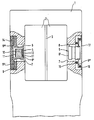
- the single figure shows a flow meter with electroacoustic transducers according to the invention.
- A, for example, cuboid, essentially solid metal or support body 1 is penetrated by a channel 2 through which a part of a gaseous medium flows.
- a rod-shaped interfering body 3 Arranged within the channel 2 is, for example, a rod-shaped interfering body 3, which generates vortices due to the flow of the gaseous medium.
- Electroacoustic transducers 4 and 5 are arranged on two opposite sides of the channel 2, one of which works as a sound transmitter and the other as a sound receiver.
- the transducers 4 and 5 are arranged such that the sound field generated passes through the region of the vortices generated by the disturbing body 3 in the gas flow.
- the sound waves generated by the transducer 4 are scattered to a greater or lesser extent, so that depending on the flow velocity of the gaseous medium, sound with different intensity is applied to the transducer 5 working as a receiver hits.
- the transducers 4 and 5 have the same structure and are arranged in principle in the same way on the metal or support body 1.
- transverse bores 7 are arranged on the metal or support body 1 on parts opposite one another with respect to the channel 2 and extend from the outside of the metal or support body 1 to the channel 2.
- the transducers 4 and 5 each have a substantially cylindrical housing 8 which faces the channel 2 with a closed end 8 '. At the opposite open end of the housing 8, a flange 8 ⁇ is arranged. Between flange 8 ⁇ and end face 8 'has in comparison to the end face 8' thick peripheral wall of the housing 8 an area of small wall thickness 8 ′′′. For this purpose, an annular groove open to the outside is formed in the peripheral wall.
- the diameter of the housing 8 is slightly smaller than the diameter of the bore 7. Accordingly, an annular gap remains between the wall of the bore 7 and the outer circumference of the housing 8.
- the flange 8 ⁇ is accommodated in a step-widened area of the bore 7 without direct contact with the metal or support body 1.
- a soft potting compound which forms a flange 8 ⁇ holding intermediate layer 9, which also has the task of transmitting structure-borne noise between the housing 8 or the flange 8 dem and the metal or Prevent supporting body 1. At the same time, this prevents mechanical vibrations or sound waves generated by the transducer 4 from reaching the transducer 5 directly via the metal or support body 1 without passing through the channel 2 or the gas flow in the channel 2.
- a piezoceramic body 10 is accommodated within the housing 8, which is provided on opposite end faces with electrodes 11, which can consist, for example, of vapor-deposited or baked metal layers. If an electrical alternating voltage is applied to the electrodes 11, mechanical vibrations or sound waves are excited due to the piezoelectric effect in the body 10. In reverse accordingly In this way, mechanical vibrations or sound waves in the piezoelectric body 10 generate an electrical alternating voltage that can be picked up at the electrodes 11.
- the electrodes 11 or the like are not shown via cables. connected to electronic circuits (not shown) for applying an alternating electrical voltage to the electrodes 11 or for processing the alternating electrical voltage that can be tapped at the electrodes 11.
- the piezoceramic body 10 is fastened on the inside of the closed end face 8 'of the housing 8 with the aid of a relatively hard casting compound which forms a thin connecting layer 12.
- Epoxy resin is particularly suitable as the material for the connecting layer 12, which may contain a high volume fraction, e.g. more than 50 vol. %, can be mixed with quartz powder to ensure a desired hardness of the connecting layer 12.
- the connecting layer 12 must be sufficiently hard to ensure good transmission of mechanical vibrations or sound waves between the end face 8 'of the housing 8 and the piezoceramic body 10. On the other hand, however, the connecting layer 12 must still be so soft that the intensity of the vibrations or sound waves at a resonance frequency has a clear main maximum and any secondary maxima that may occur in other, in particular adjacent, frequency ranges are only slightly pronounced. The secondary maxima should therefore be avoided or suppressed as much as possible, since this considerably reduces the electronic outlay for the circuits connected to the piezoceramic body 10.
- the piezoceramic body 10 is dimensioned such that an annular space remains free between the outer surface of the body 10 and the cylindrical part of the housing 8, which allows an unimpeded relative movement between the cylindrical housing part and the piezoceramic body 10. If necessary, the piezoceramic body 10 can be weighted or connected to an inert mass at its end facing away from the end face 8 'of the housing 8. For example, it is possible to connect said end of the piezoceramic body 10 to a cover or sealing compound 14 that closes the open housing side.
- the transducers 4 and 5 are generally completely identical. In the drawing, however, some details deviating from the converter 4 are shown on the converter 5.
- the flange 8 ⁇ of the transducer 5 is held between two elastic O-rings 15 and 16, which are supported on the ring step of the bore 7 or on a pressure ring or a pressure plate 17, which are arranged on or in the enlarged region of the bore 7 is.
- the O-ring 15 also serves as a seal for the enlarged area of the bore 7 with respect to the medium in the channel 2.
- the flange 8 ⁇ can be subjected to bending if the O-rings 15 and 16 are clamped with appropriate pressure between the flange 8 ⁇ and the ring step of the bore 7 or the pressure ring or the pressure plate are.
- the flange 8 ' has in the transducer 5 in the vicinity of the housing 8 an annular groove or an annular zone with a relatively small wall thickness.
- the area of the ring groove or the ring zone is resilient, similar to a diaphragm, and accordingly permits stronger vibrations of the housing 8 relative to the rest of the flange 8 '.
- the converters 4 and 5 work as follows:
- the electrodes 11 are connected to an AC voltage source via lines, not shown, so that the piezoceramic body 10 is subjected to a corresponding AC voltage. Due to the piezoelectric properties of the body 10, the body 10 begins to pulsate, ie structure-borne sound vibrations are generated in the body 10. These are transmitted via the thin connecting layer 12 to the housing 8, and because of the relative mobility between the piezoceramic body 10 and the cylindrical part of the housing 8, relatively large amplitudes can occur as soon as a resonance frequency is reached. In view of large amplitudes, it is particularly advantageous if the end face 8 'is relatively thin compared to the adjacent peripheral surfaces of the housing 8.
- peripheral wall is divided by the area 8 ′′′ with a small wall thickness, the parts of the housing 8 or the flange 8 ⁇ lying on the side of the area 8 ′′′ facing away from the end face 8 'relative should be heavy or massive.
- the sound field generated in this way in channel 2 is influenced by the vortices present in the channel of the gaseous medium flowing through channel 2. Accordingly, depending on the flow rate of the gaseous medium, a different proportion of the sound power reaches the closed end face 8 'of the housing 8 of the transducer 5 working as a receiver.
- the sound coming to the transducer 5 sets the closed end face 8 'of the associated housing 8 in vibrations, which are practically completely transferred to the piezoceramic body 10 due to the design and arrangement of the transducer 5. Due to the mechanical vibrations, a corresponding electrical alternating voltage can be tapped at the electrodes 11 of the piezoceramic body 10 of the transducer 5, which can be registered, for example, with an evaluation circuit.
- the piezoelectric body 10 in a layered manner by arranging between the outer electrodes 11 a plurality of approximately parallel metal layers between layers of piezoceramic material.
- the metal layers are alternately electrically connected to one or the other electrode 11.
- relatively low voltages are sufficient to Piezoceramic material of the body 10 to generate high electrical fields and thus pronounced mechanical vibrations.
- relatively high electrical powers can be generated.
- the housing 8 is preferably made of metal, glass or ceramic material, the respective materials being selected or composed or alloyed as far as possible in such a way that the piezoelectric or electrostrictive body 10 and the housing 8 have approximately the same density and an approximately the same coefficient of expansion when the temperature changes.
- both the housing 8 and the piezoelectric body 10 consist of ceramic materials.
- thermal conductivity of ceramic materials is relatively good, so that temperature changes in the material propagate quickly and, if need be, brief mechanical stresses occur in the ceramic material due to a temperature gradient.
- the mechanical stresses caused by temperature changes therefore have only a minor influence on the vibration behavior of the transducer.
- the good thermal conductivity and the low coefficient of expansion also have the advantage that the connection or adhesive layer between the housing 8 and the piezoelectric or electrostrictive body 10 at Tem temperature changes on the converter is only slightly stressed on shear.
- the vibrations generated by the piezoelectric or electrostrictive body 10 are transmitted particularly well to the housing 8 if ceramic material is used for the body 10 and housing 8, because the material properties are then particularly similar.
- the housing 8 When the housing 8 is made of metal, it is fundamentally possible to conductively connect one of the electrodes 11 to the metal housing 8 and to connect the housing 8 as an electrical line between the one electrode and a driver or evaluation circuit.
- the electrically conductive connection between the end face 8 'and the adjacent electrode 11 can be made, for example, by using an electrically conductive adhesive for the connecting layer 12, for example a silver-epoxy material.
- the transducers according to the invention can also be used for other purposes in addition to flow meters.
- the transducers are suitable for motion detectors which emit an ultrasound beam and evaluate the echo which may be thrown back, in order, for example, to use the Doppler effect to register movements of the objects or surfaces reflecting the sound waves.
- the transducers according to the invention are also suitable for distance detectors in which a short sound pulse is emitted and the transit time is registered. Such detectors can also be used as level meters by determining the vertical distance of the top of the product from the detector.
Landscapes
- Engineering & Computer Science (AREA)
- Physics & Mathematics (AREA)
- Acoustics & Sound (AREA)
- Multimedia (AREA)
- Mechanical Engineering (AREA)
- Piezo-Electric Transducers For Audible Bands (AREA)
- Transducers For Ultrasonic Waves (AREA)
Applications Claiming Priority (2)
| Application Number | Priority Date | Filing Date | Title |
|---|---|---|---|
| DE8805953U | 1988-05-05 | ||
| DE8805953U DE8805953U1 (de) | 1988-05-05 | 1988-05-05 | Elektroakustischer Wandler |
Publications (3)
| Publication Number | Publication Date |
|---|---|
| EP0340624A2 true EP0340624A2 (fr) | 1989-11-08 |
| EP0340624A3 EP0340624A3 (fr) | 1991-10-16 |
| EP0340624B1 EP0340624B1 (fr) | 1995-02-01 |
Family
ID=6823723
Family Applications (1)
| Application Number | Title | Priority Date | Filing Date |
|---|---|---|---|
| EP89107599A Expired - Lifetime EP0340624B1 (fr) | 1988-05-05 | 1989-04-27 | Transducteur électro-acoustique |
Country Status (2)
| Country | Link |
|---|---|
| EP (1) | EP0340624B1 (fr) |
| DE (2) | DE8805953U1 (fr) |
Cited By (6)
| Publication number | Priority date | Publication date | Assignee | Title |
|---|---|---|---|---|
| WO1994024524A1 (fr) * | 1993-04-10 | 1994-10-27 | Endress + Hauser Gmbh + Co. | Indicateur de niveau |
| WO1996018181A1 (fr) * | 1994-12-06 | 1996-06-13 | Siemens Aktiengesellschaft | Dispositif de reception d'un transducteur acoustique et debitmetre ultrasonique pourvu de celui-ci |
| EP0815954A3 (fr) * | 1996-07-04 | 2000-07-12 | Siemens Aktiengesellschaft | Transducteur sonore, en particulier transducteur à ultrason |
| EP1491865A1 (fr) * | 2003-06-24 | 2004-12-29 | Bürkert Werke GmbH & Co. | Débitmètre à tourbillons |
| EP3098622B1 (fr) * | 2015-05-29 | 2020-01-01 | Consilium SAL Navigation AB | Dispositif électronique intégré dans la coque pour un navire |
| CN112083063A (zh) * | 2019-06-12 | 2020-12-15 | 千竣科技有限公司 | 超声波传感装置 |
Family Cites Families (8)
| Publication number | Priority date | Publication date | Assignee | Title |
|---|---|---|---|---|
| JPS5318893B2 (fr) * | 1971-12-03 | 1978-06-17 | ||
| US3943388A (en) * | 1974-06-27 | 1976-03-09 | Fred M. Dellorfano, Jr. | Electroacoustic transducer of the flexural vibrating diaphragm type |
| DE2839091C2 (de) * | 1978-09-08 | 1980-03-13 | Honeywell-Elac-Nautik Gmbh, 2300 Kiel | Elektroakustischer Wandler |
| US4240002A (en) * | 1979-04-02 | 1980-12-16 | Motorola, Inc. | Piezoelectric transducer arrangement with integral terminals and housing |
| JPS5832559B2 (ja) * | 1979-07-04 | 1983-07-13 | 株式会社 モリタ製作所 | 空中超音波パルスの伝送方式並びにこれに用いる超音波送受波具 |
| DE3005708C2 (de) * | 1980-02-15 | 1984-08-30 | Siemens AG, 1000 Berlin und 8000 München | Wandlerplatte für piezoelektrische Wandler |
| DE3012038C2 (de) * | 1980-03-28 | 1982-08-19 | Honeywell-Elac-Nautik Gmbh, 2300 Kiel | Elektroakustischer Wasserschallwandler |
| US4556814A (en) * | 1984-02-21 | 1985-12-03 | Ngk Spark Plug Co., Ltd. | Piezoelectric ultrasonic transducer with porous plastic housing |
-
1988
- 1988-05-05 DE DE8805953U patent/DE8805953U1/de not_active Expired
-
1989
- 1989-04-27 EP EP89107599A patent/EP0340624B1/fr not_active Expired - Lifetime
- 1989-04-27 DE DE58908955T patent/DE58908955D1/de not_active Expired - Lifetime
Cited By (8)
| Publication number | Priority date | Publication date | Assignee | Title |
|---|---|---|---|---|
| WO1994024524A1 (fr) * | 1993-04-10 | 1994-10-27 | Endress + Hauser Gmbh + Co. | Indicateur de niveau |
| US5866815A (en) * | 1993-04-10 | 1999-02-02 | Endress +Hauser Gmbh +Co. | Fill-level indicator |
| WO1996018181A1 (fr) * | 1994-12-06 | 1996-06-13 | Siemens Aktiengesellschaft | Dispositif de reception d'un transducteur acoustique et debitmetre ultrasonique pourvu de celui-ci |
| EP0815954A3 (fr) * | 1996-07-04 | 2000-07-12 | Siemens Aktiengesellschaft | Transducteur sonore, en particulier transducteur à ultrason |
| EP1491865A1 (fr) * | 2003-06-24 | 2004-12-29 | Bürkert Werke GmbH & Co. | Débitmètre à tourbillons |
| EP3098622B1 (fr) * | 2015-05-29 | 2020-01-01 | Consilium SAL Navigation AB | Dispositif électronique intégré dans la coque pour un navire |
| US10991354B2 (en) | 2015-05-29 | 2021-04-27 | Consilium Sal Navigation Ab | Hull-fitted electronic device for a vessel |
| CN112083063A (zh) * | 2019-06-12 | 2020-12-15 | 千竣科技有限公司 | 超声波传感装置 |
Also Published As
| Publication number | Publication date |
|---|---|
| EP0340624B1 (fr) | 1995-02-01 |
| DE8805953U1 (de) | 1988-07-07 |
| DE58908955D1 (de) | 1995-03-16 |
| EP0340624A3 (fr) | 1991-10-16 |
Similar Documents
| Publication | Publication Date | Title |
|---|---|---|
| EP0840655B1 (fr) | Transducteur ultrasonore | |
| DE2934031C2 (de) | Ultraschallwandler | |
| EP3433585B1 (fr) | Transducteur ultrasonore destiné à être employé dans un débitmètre ultrasonore ou dans un niveaumètre ultrasonore | |
| DE4431511B4 (de) | Schallschwingungswandler | |
| DE2526817A1 (de) | Wandlerkopplung | |
| WO2020245064A2 (fr) | Transducteur ultrasonique et procédé de fabrication d'un transducteur ultrasonique | |
| WO1996018181A1 (fr) | Dispositif de reception d'un transducteur acoustique et debitmetre ultrasonique pourvu de celui-ci | |
| EP0031049B1 (fr) | Transducteur acoustique | |
| DE102011090079A1 (de) | Ultraschallwandler für ein Ultraschall-Durchflussmessgerät | |
| WO2009077377A1 (fr) | Transducteur à ultrasons pour déterminer et/ou contrôler un courant de milieu mesurable dans un tuyau de mesure | |
| EP0340624B1 (fr) | Transducteur électro-acoustique | |
| US5654101A (en) | Acoustic composite material for an ultrasonic phased array | |
| DE202007007135U1 (de) | Piezoelektrischer Ultraschallwandler | |
| EP0749005A2 (fr) | Transducteur acoustique | |
| EP1238388B1 (fr) | Transducteur a ultrasons piezoelectrique comportant un boitier et une couche isolante | |
| EP0590176A1 (fr) | Transducteur ultrasonore muni d'une couche d'adaptation acoustique | |
| WO1999010874A1 (fr) | Transducteur | |
| DE19758243A1 (de) | Schallwandlersystem | |
| EP0505482A1 (fr) | Dispositif insonorise de retenue de transducteurs ultrasoniques | |
| EP1329875A2 (fr) | Transducteur à ultrason à électrodes plastiques conducteurs | |
| DE69205148T2 (de) | Fühler zum messen von hochintensitätakustischen feldern. | |
| DE102013010654A1 (de) | Biegewellenlautsprecher | |
| DE3315649C1 (de) | Ultraschallprüfkopf zur zerstörungsfreien Prüfung heißer Prüfstücke | |
| WO2020035336A1 (fr) | Dispositif de mesure pour la détermination d'une grandeur de fluide | |
| DE19750179A1 (de) | Schallwandler |
Legal Events
| Date | Code | Title | Description |
|---|---|---|---|
| PUAI | Public reference made under article 153(3) epc to a published international application that has entered the european phase |
Free format text: ORIGINAL CODE: 0009012 |
|
| AK | Designated contracting states |
Kind code of ref document: A2 Designated state(s): CH DE FR GB IT LI NL |
|
| PUAL | Search report despatched |
Free format text: ORIGINAL CODE: 0009013 |
|
| AK | Designated contracting states |
Kind code of ref document: A3 Designated state(s): CH DE FR GB IT LI NL |
|
| RHK1 | Main classification (correction) |
Ipc: G10K 11/00 |
|
| 17P | Request for examination filed |
Effective date: 19911223 |
|
| 17Q | First examination report despatched |
Effective date: 19931217 |
|
| GRAA | (expected) grant |
Free format text: ORIGINAL CODE: 0009210 |
|
| AK | Designated contracting states |
Kind code of ref document: B1 Designated state(s): CH DE FR GB IT LI NL |
|
| GBT | Gb: translation of ep patent filed (gb section 77(6)(a)/1977) |
Effective date: 19950127 |
|
| REF | Corresponds to: |
Ref document number: 58908955 Country of ref document: DE Date of ref document: 19950316 |
|
| ITF | It: translation for a ep patent filed | ||
| ET | Fr: translation filed | ||
| PLBE | No opposition filed within time limit |
Free format text: ORIGINAL CODE: 0009261 |
|
| STAA | Information on the status of an ep patent application or granted ep patent |
Free format text: STATUS: NO OPPOSITION FILED WITHIN TIME LIMIT |
|
| 26N | No opposition filed | ||
| REG | Reference to a national code |
Ref country code: GB Ref legal event code: IF02 |
|
| PGFP | Annual fee paid to national office [announced via postgrant information from national office to epo] |
Ref country code: IT Payment date: 20060430 Year of fee payment: 18 |
|
| REG | Reference to a national code |
Ref country code: CH Ref legal event code: PFA Owner name: HOENTZSCH GMBH Free format text: HOENTZSCH GMBH#ROBERT-BOSCH-STRASSE 8#WAIBLINGEN-HEGNACH (DE) -TRANSFER TO- HOENTZSCH GMBH#ROBERT-BOSCH-STRASSE 8#WAIBLINGEN-HEGNACH (DE) |
|
| PGFP | Annual fee paid to national office [announced via postgrant information from national office to epo] |
Ref country code: DE Payment date: 20080417 Year of fee payment: 20 Ref country code: CH Payment date: 20080421 Year of fee payment: 20 |
|
| PGFP | Annual fee paid to national office [announced via postgrant information from national office to epo] |
Ref country code: NL Payment date: 20080421 Year of fee payment: 20 |
|
| PGFP | Annual fee paid to national office [announced via postgrant information from national office to epo] |
Ref country code: FR Payment date: 20080421 Year of fee payment: 20 |
|
| PGFP | Annual fee paid to national office [announced via postgrant information from national office to epo] |
Ref country code: GB Payment date: 20080424 Year of fee payment: 20 |
|
| REG | Reference to a national code |
Ref country code: CH Ref legal event code: PL |
|
| REG | Reference to a national code |
Ref country code: GB Ref legal event code: PE20 Expiry date: 20090426 |
|
| PG25 | Lapsed in a contracting state [announced via postgrant information from national office to epo] |
Ref country code: NL Free format text: LAPSE BECAUSE OF EXPIRATION OF PROTECTION Effective date: 20090427 |
|
| NLV7 | Nl: ceased due to reaching the maximum lifetime of a patent |
Effective date: 20090427 |
|
| PG25 | Lapsed in a contracting state [announced via postgrant information from national office to epo] |
Ref country code: IT Free format text: LAPSE BECAUSE OF NON-PAYMENT OF DUE FEES Effective date: 20070427 |
|
| PG25 | Lapsed in a contracting state [announced via postgrant information from national office to epo] |
Ref country code: GB Free format text: LAPSE BECAUSE OF EXPIRATION OF PROTECTION Effective date: 20090426 |