EP1491865A1 - Débitmètre à tourbillons - Google Patents
Débitmètre à tourbillons Download PDFInfo
- Publication number
- EP1491865A1 EP1491865A1 EP04014722A EP04014722A EP1491865A1 EP 1491865 A1 EP1491865 A1 EP 1491865A1 EP 04014722 A EP04014722 A EP 04014722A EP 04014722 A EP04014722 A EP 04014722A EP 1491865 A1 EP1491865 A1 EP 1491865A1
- Authority
- EP
- European Patent Office
- Prior art keywords
- housing
- flow sensor
- sensor according
- ultrasound
- sound
- Prior art date
- Legal status (The legal status is an assumption and is not a legal conclusion. Google has not performed a legal analysis and makes no representation as to the accuracy of the status listed.)
- Withdrawn
Links
Images
Classifications
-
- G—PHYSICS
- G01—MEASURING; TESTING
- G01N—INVESTIGATING OR ANALYSING MATERIALS BY DETERMINING THEIR CHEMICAL OR PHYSICAL PROPERTIES
- G01N29/00—Investigating or analysing materials by the use of ultrasonic, sonic or infrasonic waves; Visualisation of the interior of objects by transmitting ultrasonic or sonic waves through the object
- G01N29/22—Details, e.g. general constructional or apparatus details
- G01N29/222—Constructional or flow details for analysing fluids
-
- G—PHYSICS
- G01—MEASURING; TESTING
- G01F—MEASURING VOLUME, VOLUME FLOW, MASS FLOW OR LIQUID LEVEL; METERING BY VOLUME
- G01F1/00—Measuring the volume flow or mass flow of fluid or fluent solid material wherein the fluid passes through a meter in a continuous flow
- G01F1/05—Measuring the volume flow or mass flow of fluid or fluent solid material wherein the fluid passes through a meter in a continuous flow by using mechanical effects
- G01F1/20—Measuring the volume flow or mass flow of fluid or fluent solid material wherein the fluid passes through a meter in a continuous flow by using mechanical effects by detection of dynamic effects of the flow
- G01F1/32—Measuring the volume flow or mass flow of fluid or fluent solid material wherein the fluid passes through a meter in a continuous flow by using mechanical effects by detection of dynamic effects of the flow using swirl flowmeters
- G01F1/325—Means for detecting quantities used as proxy variables for swirl
- G01F1/3282—Means for detecting quantities used as proxy variables for swirl for detecting variations in infrasonic, sonic or ultrasonic waves, due to modulation by passing through the swirling fluid
-
- G—PHYSICS
- G01—MEASURING; TESTING
- G01N—INVESTIGATING OR ANALYSING MATERIALS BY DETERMINING THEIR CHEMICAL OR PHYSICAL PROPERTIES
- G01N29/00—Investigating or analysing materials by the use of ultrasonic, sonic or infrasonic waves; Visualisation of the interior of objects by transmitting ultrasonic or sonic waves through the object
- G01N29/02—Analysing fluids
- G01N29/024—Analysing fluids by measuring propagation velocity or propagation time of acoustic waves
-
- G—PHYSICS
- G01—MEASURING; TESTING
- G01N—INVESTIGATING OR ANALYSING MATERIALS BY DETERMINING THEIR CHEMICAL OR PHYSICAL PROPERTIES
- G01N29/00—Investigating or analysing materials by the use of ultrasonic, sonic or infrasonic waves; Visualisation of the interior of objects by transmitting ultrasonic or sonic waves through the object
- G01N29/22—Details, e.g. general constructional or apparatus details
- G01N29/24—Probes
- G01N29/2418—Probes using optoacoustic interaction with the material, e.g. laser radiation, photoacoustics
- G01N29/2425—Probes using optoacoustic interaction with the material, e.g. laser radiation, photoacoustics optoacoustic fluid cells therefor
-
- G—PHYSICS
- G01—MEASURING; TESTING
- G01N—INVESTIGATING OR ANALYSING MATERIALS BY DETERMINING THEIR CHEMICAL OR PHYSICAL PROPERTIES
- G01N2291/00—Indexing codes associated with group G01N29/00
- G01N2291/01—Indexing codes associated with the measuring variable
- G01N2291/012—Phase angle
-
- G—PHYSICS
- G01—MEASURING; TESTING
- G01N—INVESTIGATING OR ANALYSING MATERIALS BY DETERMINING THEIR CHEMICAL OR PHYSICAL PROPERTIES
- G01N2291/00—Indexing codes associated with group G01N29/00
- G01N2291/10—Number of transducers
- G01N2291/102—Number of transducers one emitter, one receiver
Definitions
- the invention relates to a flow sensor based on the vortex principle, the vertebrae being detected using ultrasound.
- the vortex method is a widely used and well-described principle of flow measurement on gases and liquids.
- An interfering body also known as a bluff body
- An interfering body is introduced into the flow channel, on which vortices detach according to the principle of a Karman vortex street.
- These vortices can then be recognized via pressure sensors, optical sensors or acoustic sensors, which preferably work with ultrasound.
- the eddy frequency of the vortices is proportional to the volume flow of the medium.
- a flow sensor based on the vortex principle which uses ultrasound sensors to detect the vertebrae.
- an ultrasound path is integrated in the sensor perpendicular to the flow channel.
- the sound wave penetrates the measured medium perpendicular to its direction of flow.
- the flow sensor For use of the flow sensor in the hazardous area, it is desirable to separate the zones between the hazardous areas Medium (“Zone 0") and the electrical components ("Zone 1"). If the electronic components are not in “Zone 0", the design effort required for approval of the sensor by the competent authority is significantly lower.
- the ultrasound is usually generated with electronic components, for example with piezo elements. It is therefore desirable to separate the piezo crystal from the medium in accordance with explosion protection regulations and to achieve zone separation. This can be achieved, for example, by means of a metallic separating membrane (for example a tube wall) between the fluid channel and the piezo element. If the piezo element is attached to the outside of a tube wall, the problem arises that the sound is largely transmitted via the metal and not, as desired, via the air gap between the piezo elements.
- a flow sensor is therefore required which both achieves the zone separation between "Zone 0" and "Zone 1" from the point of view of explosion protection and also ensures adequate acoustic transmission of the ultrasound over the air gap.
- the flow sensor comprises a housing with a flow channel crossing the housing and with at least one ultrasound transmitter and at least one ultrasound receiver, which are arranged in the housing next to the flow channel.
- the ultrasound transmitter and the ultrasound receiver are separated from the adjacent body of the housing by one or more gaps. They each have a membrane facing the flow channel. The gaps ensure that only a small amount of ultrasound is transmitted to the housing.
- the membrane pointing towards the flow channel leads to a zone separation with good ultrasound transmission at the same time.
- Ultrasonic transmitters and ultrasonic receivers are preferably each implemented in their own sound elements, which contact the housing only to a limited extent.
- the housing is preferably a solid metal housing, in which a first through bore realizes the flow channel.
- the housing comprises a second through bore, the central axis of which intersects the central axis of the first through bore essentially perpendicularly and which has a first diameter at the two outer ends and a second smaller diameter in the middle.
- This bore can receive an ultrasonic transmitter and an ultrasonic receiver and bring them close to the flow channel.
- the sound elements are preferably cylindrical in shape and contain a blind hole running essentially perpendicular to a floor surface.
- a piezo element is attached to the bottom surface, e.g. the piezo element can be glued.
- the bottom surface forms a membrane.
- the sound elements are provided with projecting webs. After the sound elements have been installed in the sensor housing, only the webs touch the housing and one or more gaps are formed. The connection between the housing and the sound element is therefore not made by an extensive area, but preferably only locally.
- the webs preferably have a vertical height above the sound element surface of a maximum of 0.3 mm and a distance of at least 6 mm from one another. This creates an air gap that has a geometrical size has a pressure-resistant effect and serves as a zone separation between "Zone 0" and "Zone 1".
- the sound elements are connected to the housing and the flow channel in such a way that the ultrasound in the desired frequency range is emitted only slightly onto the housing and flow channel, but preferably into the air lying in front of the sound elements.
- the webs are made of metal. They can easily be included in the manufacture of the sound elements.
- a gap or several gaps between the ultrasound transmitter and the ultrasound receiver and the housing is achieved by means of a sound element which has an area with a small diameter onto which a ring is attached.
- This ring is preferably made of plastic, which conducts the sound worse than metal. The locally limited contact between the sound element and the housing can thus take place over a somewhat larger area.
- the ring has a larger outer diameter than the area of the shell element without a ring attached. A gap is thus created and the sound element is integrated pressure-tight in the housing of the flow sensor in accordance with the pressure-resistant encapsulation.
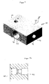
- FIG. 1 shows a three-dimensional representation of a housing 10 of a flow sensor according to the invention.
- a flow channel 12 runs as a continuous bore longitudinally through the housing 10, starting at an inlet 14 not visible in FIG. 1 and ending at an outlet 16.
- a bore 18 can be used to create a bluff body for generating the vortex for the vortex Principle.
- a second continuous bore 21 runs from an opening 20 to an opposite opening 22, which is not visible in FIG. 1.
- the central axis of this continuous bore intersects the central axis of the flow channel 12 essentially perpendicularly.
- the bore has a larger diameter D at its two outer ends and a smaller diameter d in the central region.
- Sound elements with piezo elements can be introduced into the bore area with the larger diameter D. These sound elements are explained in more detail with reference to FIGS. 2 and 3.
- the liquid flowing into the housing 10 at the inlet 14 into the flow channel 12 is swirled by the disturbing body which is introduced into the flow channel via the bore 18.
- the vortex section thus generated crosses the bore 21 and thus runs between the two sound elements.
- the liquid then leaves the flow channel 12 and thus the housing 10 via the outlet 16.
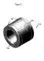
- FIG. 2 shows an embodiment of a sound element 24.
- This is a metal cylinder with an inserted blind hole 26.
- the blind hole runs essentially perpendicular to a bottom surface of the sound element 24.
- the remaining wall thickness at the bottom of the blind hole is sufficient to comply with the applicable regulations to ensure zone separation.
- the bottom surface of the shell element forms a membrane 27.
- a piezo element 28 is attached on the inside to the bottom of the blind hole. This can for example by gluing.
- Two circumferential metal webs 30 are realized on the jacket surface of the cylindrical shell element 24. The metal webs 30 run parallel to one another and parallel to the bottom surface or membrane 27 of the sound element.
- These metal webs preferably have a vertical height above the cylinder surface of at most 0.3 mm and a distance from one another of at least 6 mm.
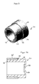
- FIG. 3 shows a further embodiment of a shell element 24.
- the basic shape of the shell element is again cylindrical and contains a blind hole which runs essentially perpendicular to a bottom surface.
- the bottom surface again forms the membrane 27.
- a piezo element 28 is glued to the bottom surface.
- a portion 32 of the metal cylinder facing the opening of the blind hole is turned off, so that a step 33 is created.
- the outer radius on this side of the cylinder is smaller than the outer radius in the partial area 34 on the closed cylinder side.
- a ring 35 is placed on partial area 32 of the shell element, as can be seen in FIG. 3a.
- Figure 3a shows a schematic longitudinal section through the sound element 24 of Figure 3. The attached ring 35 touches the step 33.
- Ring 35 can be, for example, a plastic ring that conducts the sound poorly compared to metal.
- the outer diameter in the partial area 34 of the shell element is smaller than the outer diameter of the ring 35. If this sound element with the ring attached is inserted into one of the openings 20 or 22 of the housing 10, the sound element only touches the housing 10 locally in the area of the ring 35. Thus, in turn, a pressure-resistant gap is formed between the sound element 24 and the housing 10.
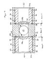
- Figure 4 shows a schematic section through the housing 10 along the section line IV-IV shown in Figure 1, i.e. through the intersection of the flow channel 12 and the bore 21.
- a sound element 24a, 24b corresponding to the embodiment according to FIG. 2 is inserted into the openings 20 and 22, respectively.
- the interfering body to be introduced through hole 18 is not shown.
- a piezo element 28a, 28b is glued to the bottom of the sound elements 24a, 24b.
- sound element 24a with piezo element 28a is, for example, an ultrasound transmitter and sound element 24b with piezo element 28b is an ultrasound receiver.
- the flow channel 12 runs between these two sound elements perpendicular to the plane of the drawing.
- the liquid that flows through flow channel 12 is already swirled at this point.
- the sectional view clearly shows gaps 36 which result from metal webs 30 between the lateral surfaces of the sound elements 24a, 24b and the housing 10.
- FIG. 4 shows the area of "Zone 0" and “Zone 1".
- “Zone 0” lies between membrane 27a and membrane 27b.
- the electrical components piezo element 28a and 28b are each in "Zone 1".
- Membranes 27a and 27b ensure that they cannot come into contact with the liquid.
- Membranes 27a and 27b separate the zones, ie the electrical components of the ultrasound transmitter and the ultrasound receiver, in particular the piezo elements 28a and 28b, do not come into contact with the explosive liquid in the flow channel.
- sealing rings 38a, 38b are inserted between the housing 10 and the end face of the sound elements 24a, 24b. These sealing rings 38a and 38b form gaps 40 between the end faces of the sound elements and housing 10.
- the ultrasound transmission from the ultrasound transmitter 24a, 28a to the ultrasound receiver 24b, 28b takes place via membrane 27a, flow channel 12 and membrane 27b.
- a sound crossing on Housing 10 is largely avoided since the sound elements 24 contact the housing 10 only locally via the metal webs 30 or via sealing rings 38a, 38b.
Landscapes
- Physics & Mathematics (AREA)
- General Physics & Mathematics (AREA)
- Biochemistry (AREA)
- Life Sciences & Earth Sciences (AREA)
- Chemical & Material Sciences (AREA)
- Analytical Chemistry (AREA)
- Health & Medical Sciences (AREA)
- General Health & Medical Sciences (AREA)
- Immunology (AREA)
- Pathology (AREA)
- Acoustics & Sound (AREA)
- Optics & Photonics (AREA)
- Fluid Mechanics (AREA)
- Measurement Of Mechanical Vibrations Or Ultrasonic Waves (AREA)
- Measuring Volume Flow (AREA)
Applications Claiming Priority (2)
| Application Number | Priority Date | Filing Date | Title |
|---|---|---|---|
| DE20309788U DE20309788U1 (de) | 2003-06-24 | 2003-06-24 | Durchflussmesser nach dem Vortex-Prinzip |
| DE20309788U | 2003-06-24 |
Publications (1)
| Publication Number | Publication Date |
|---|---|
| EP1491865A1 true EP1491865A1 (fr) | 2004-12-29 |
Family
ID=33395177
Family Applications (1)
| Application Number | Title | Priority Date | Filing Date |
|---|---|---|---|
| EP04014722A Withdrawn EP1491865A1 (fr) | 2003-06-24 | 2004-06-23 | Débitmètre à tourbillons |
Country Status (2)
| Country | Link |
|---|---|
| EP (1) | EP1491865A1 (fr) |
| DE (1) | DE20309788U1 (fr) |
Cited By (1)
| Publication number | Priority date | Publication date | Assignee | Title |
|---|---|---|---|---|
| RU2486475C1 (ru) * | 2011-12-22 | 2013-06-27 | Федеральное государственное бюджетное образовательное учреждение высшего профессионального образования "Сибирский государственный технологический университет" (СибГТУ) | Вихревой расходомер |
Citations (5)
| Publication number | Priority date | Publication date | Assignee | Title |
|---|---|---|---|---|
| US3940986A (en) * | 1974-04-30 | 1976-03-02 | Yokogawa Electric Works, Ltd. | Flow Velocity measuring device |
| EP0340624A2 (fr) * | 1988-05-05 | 1989-11-08 | Höntzsch Gmbh | Transducteur électro-acoustique |
| EP0344927A1 (fr) * | 1988-05-10 | 1989-12-06 | Scheme Engineering Limited | Débitmètre |
| DE3832947A1 (de) * | 1988-09-28 | 1990-03-29 | Siemens Ag | Ultraschall-wandler, insbesondere fuer luftmengenmesser |
| DE19723488A1 (de) * | 1997-06-05 | 1998-12-10 | Elster Produktion Gmbh | Einrichtung zum Befestigen eines Ultraschallwandlers an einem Meßgerät |
Family Cites Families (2)
| Publication number | Priority date | Publication date | Assignee | Title |
|---|---|---|---|---|
| NO174309C (no) * | 1987-04-24 | 1994-04-13 | Norske Stats Oljeselskap | Elektroakustisk transducer for anordning i et gassformig fluid, særlig for måling av strömningsghastigheten i et rör under eksplosjonsfarlige forhol |
| GB2226409B (en) * | 1988-12-05 | 1992-12-23 | Mitsubishi Electric Corp | Karman's vortex flow meter |
-
2003
- 2003-06-24 DE DE20309788U patent/DE20309788U1/de not_active Expired - Lifetime
-
2004
- 2004-06-23 EP EP04014722A patent/EP1491865A1/fr not_active Withdrawn
Patent Citations (5)
| Publication number | Priority date | Publication date | Assignee | Title |
|---|---|---|---|---|
| US3940986A (en) * | 1974-04-30 | 1976-03-02 | Yokogawa Electric Works, Ltd. | Flow Velocity measuring device |
| EP0340624A2 (fr) * | 1988-05-05 | 1989-11-08 | Höntzsch Gmbh | Transducteur électro-acoustique |
| EP0344927A1 (fr) * | 1988-05-10 | 1989-12-06 | Scheme Engineering Limited | Débitmètre |
| DE3832947A1 (de) * | 1988-09-28 | 1990-03-29 | Siemens Ag | Ultraschall-wandler, insbesondere fuer luftmengenmesser |
| DE19723488A1 (de) * | 1997-06-05 | 1998-12-10 | Elster Produktion Gmbh | Einrichtung zum Befestigen eines Ultraschallwandlers an einem Meßgerät |
Cited By (1)
| Publication number | Priority date | Publication date | Assignee | Title |
|---|---|---|---|---|
| RU2486475C1 (ru) * | 2011-12-22 | 2013-06-27 | Федеральное государственное бюджетное образовательное учреждение высшего профессионального образования "Сибирский государственный технологический университет" (СибГТУ) | Вихревой расходомер |
Also Published As
| Publication number | Publication date |
|---|---|
| DE20309788U1 (de) | 2004-11-04 |
Similar Documents
| Publication | Publication Date | Title |
|---|---|---|
| DE102008049891B4 (de) | Strömungsrichter für ein Durchflussmessgerät, insbesondere ein Ultraschallmessgerät | |
| EP2044392B1 (fr) | Système de mesure pour un milieu s'écoulant dans un conduit de traitement | |
| DE2458901C3 (de) | Strömungsmesser | |
| EP0800062A2 (fr) | Dispositif pour la mesure de la vitesse d'écoulement d'un fluide | |
| EP3314214B1 (fr) | Débitmètre comprenant un canal de mesure et des canaux auxiliaires | |
| EP2827111B1 (fr) | Compteur à ultrasons | |
| DE102006062552B4 (de) | Verfahren und Vorrichtung zur Durchflussmessung | |
| DE10240189A1 (de) | Verfahren zum Ermitteln eines Massendurchflusses eines in einer Rohrleitung strömenden Fluids | |
| EP3404372B1 (fr) | Débitmètre ultrasonique | |
| DE102011118921A1 (de) | Vortex-Durchflussmessgerät und diesbezügliche Faserdurchführung | |
| DE2138348B2 (de) | Messduese fuer die durchflussmessung eines fluids durch eine rohrleitung | |
| DE102009005134A1 (de) | Druckfühlereinrichtung für eine explosive oder korrosive Atmosphäre | |
| EP1227303B1 (fr) | Débimètre à ultrasons avec section de mesure interchangeable | |
| DE3802708A1 (de) | Wirbelmessgeraetkoerper | |
| EP3514505B1 (fr) | Débitmètre | |
| DE19648784C2 (de) | Ultraschall-Durchflußmesser | |
| EP1491865A1 (fr) | Débitmètre à tourbillons | |
| EP1423663B1 (fr) | Compteur de courant tourbillonnaire resistant a la corrosion | |
| EP1967827A1 (fr) | Débitmètre à tourbillon pour la saisie de la vitesse d'écoulement dans une canalisation | |
| EP0301258B1 (fr) | Procédé pour mesurer le débit des fluides | |
| DE102020126021A1 (de) | Fluidmesseinrichtung | |
| EP0682772A1 (fr) | Sonde rheometrique | |
| EP0887626A1 (fr) | Ensembles de substitution pour débitmètres de volume et débitmètres à tourbillon correspondants | |
| DE202022000672U1 (de) | Vorrichtung zur Messung einer Durchflussgeschwindigkeit eines Fluids | |
| EP0431345A2 (fr) | Capteur pour la mesure de pression d'un fluide passant dans un tuyau |
Legal Events
| Date | Code | Title | Description |
|---|---|---|---|
| PUAI | Public reference made under article 153(3) epc to a published international application that has entered the european phase |
Free format text: ORIGINAL CODE: 0009012 |
|
| AK | Designated contracting states |
Kind code of ref document: A1 Designated state(s): AT BE BG CH CY CZ DE DK EE ES FI FR GB GR HU IE IT LI LU MC NL PL PT RO SE SI SK TR |
|
| AX | Request for extension of the european patent |
Extension state: AL HR LT LV MK |
|
| 17P | Request for examination filed |
Effective date: 20050624 |
|
| AKX | Designation fees paid |
Designated state(s): DE FR GB IT |
|
| STAA | Information on the status of an ep patent application or granted ep patent |
Free format text: STATUS: THE APPLICATION IS DEEMED TO BE WITHDRAWN |
|
| 18D | Application deemed to be withdrawn |
Effective date: 20070103 |