EP0340669A2 - Vorrichtung für Tierversuche - Google Patents
Vorrichtung für Tierversuche Download PDFInfo
- Publication number
- EP0340669A2 EP0340669A2 EP89107770A EP89107770A EP0340669A2 EP 0340669 A2 EP0340669 A2 EP 0340669A2 EP 89107770 A EP89107770 A EP 89107770A EP 89107770 A EP89107770 A EP 89107770A EP 0340669 A2 EP0340669 A2 EP 0340669A2
- Authority
- EP
- European Patent Office
- Prior art keywords
- housing
- temperature
- air
- air fan
- heater
- Prior art date
- Legal status (The legal status is an assumption and is not a legal conclusion. Google has not performed a legal analysis and makes no representation as to the accuracy of the status listed.)
- Granted
Links
Images



Classifications
-
- A—HUMAN NECESSITIES
- A01—AGRICULTURE; FORESTRY; ANIMAL HUSBANDRY; HUNTING; TRAPPING; FISHING
- A01K—ANIMAL HUSBANDRY; AVICULTURE; APICULTURE; PISCICULTURE; FISHING; REARING OR BREEDING ANIMALS, NOT OTHERWISE PROVIDED FOR; NEW BREEDS OF ANIMALS
- A01K1/00—Housing animals; Equipment therefor
- A01K1/02—Pigsties; Dog-kennels; Rabbit-hutches or the like
- A01K1/03—Housing for domestic or laboratory animals
- A01K1/031—Cages for laboratory animals; Cages for measuring metabolism of animals
- A01K1/0313—Cages for laboratory animals; Cages for measuring metabolism of animals comprising forced ventilation means
-
- A—HUMAN NECESSITIES
- A01—AGRICULTURE; FORESTRY; ANIMAL HUSBANDRY; HUNTING; TRAPPING; FISHING
- A01K—ANIMAL HUSBANDRY; AVICULTURE; APICULTURE; PISCICULTURE; FISHING; REARING OR BREEDING ANIMALS, NOT OTHERWISE PROVIDED FOR; NEW BREEDS OF ANIMALS
- A01K1/00—Housing animals; Equipment therefor
- A01K1/02—Pigsties; Dog-kennels; Rabbit-hutches or the like
- A01K1/03—Housing for domestic or laboratory animals
- A01K1/031—Cages for laboratory animals; Cages for measuring metabolism of animals
Definitions
- the present invention relates to an animal experiment apparatus for subjecting small animals such as mice, rats and guinea pigs to an environmental change such as a change in light and a change in temperature.
- An apparatus used for such an experiment generally has the following structure.
- a housing which is provided with doors at the front surface thereof is vertically partitioned into a plurality of chambers by latticed shelves.
- a fluorescent lamp is provided on the ceiling or the side wall above each of the doors of the housing, and an air fan is provided on the ceiling.
- the temperature of the housing is regulated to a low temperature or a high temperature by a cooler or a heater. Plastic cages containing small animals are placed on the shelves.
- the temperature is lowered by the cooler and raised by the heater.
- the doors of the cooled or heated housing are left open and the cages are put into and out of the housing.
- the air driven from the air fan is diffused immediately after passing through the cooler or the heater, cold or hot air flows at a high rate to the cages in the vicinity of the cooler or the heater.
- the environmental conditions are different between the cages in the vicinity of the cooler or the heater and the cages distant therefrom.
- the conventional apparatus described above is only capable of either a low-temperature stress test or a high-temperature stress test.
- the temperature of the housing can be either lowered or raised by the cooler or the heater provided therein, but the opposite temperature change must be given by keeping the doors open. Therefore, whenever it is necessary to lower or raise the temperature, the doors are opened by hand and the cages are carried out, thereby lowering the workability.
- the conventional apparatus is inferior in responsiveness, and it is not easy to obtain high reproducibility and, hence, data having high reliability from such apparatus.
- an animal experiment apparatus comprising: a housing; partition shelves for vertically dividing the housing into a plurality of chambers and placing cages containing small animals thereon; a heater and a cooler provided in the housing; a commutator plate for controlling the direction of flow of the heated air or the cooled air blown from the heater or the cooler; and a brightness-controllable lighting fixture provided in each chamber.
- an animal experiment apparatus comprising: a housing; partition shelves for vertically dividing the housing into a plurality of chambers and placing cages containing small animals thereon; a heater and a cooler provided in the housing; a commutator for controlling the direction of flow of the heated air or the cooled air blown from the heater or the cooler; a brightness-controllable lighting fixture provided in the housing; a moistening device for moistening the interior of the housing; a temperature sensor for detecting the temperature of the housing and a humidity sensor for detecting the humidity of the housing; a control unit which compares the detection signals from the temperature sensor and the humidity sensor with the respective set values and so controls the heater, the cooler and the moistening device that the detected values are in the range of the respective set values; a value setting device for setting the respective values in the control unit; and a recorder for recording the detection signals output from the temperature sensor and the humidity sensor.
- the brightness is substantially the same in the cage containing a small animal no matter which chamber it is laid in.
- the commutator plate controls the flow of the air blown from the air fan, it is possible to make the flow rate and the airflow of the air blown to the cages substantially uniform.
- the temperature of the housing accommodating the cages which contain small animals is controlled by the heater or the cooler and the humidity thereof is controlled by the moistening device.
- the operations of these devices are controlled by the control unit.
- the temperature and the humidity of the housing are constantly detected by the temperature sensor and the humidity sensor and the detected values are output to the control unit.
- the control unit compares the detected values with the set values and so controls the heater, the cooler and the moistening device that the detected values of the temperature and the humidity are in the range of the set values.
- the set values in the control unit are set by the value setting device, and the temperature and the humidity of the housing are constantly recorded by the recorder which supplies the output signals from the temperature sensor and the humidity sensor.
- the lighting fixture is brightness-controllable, it is possible to so control the intensity of the light cast on each cage as to be constant irrespective of the location and the number of the cages.
- the animal experiment apparatus of the present invention it is possible to make the environmental conditions for small animals substantially uniform to such an extent that the brightnesses, the flow rates and the air flows with respect to the cages containing small animals become substantially uniform. Since the temperature of the housing accommodating the cages which contain small animals is controlled not manually but automatically, the workability is improved.
- the temperature of the housing is constantly detected and input to the control unit and the signals are constantly supplied from the control unit to the heater and the cooler, even if the measured value deviates from the set value, the temperature of the housing is adjusted to the range of the set value with good responsiveness. Thus, it is easy to obtain data having good reproducibility and high reliability.
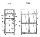
- FIG. 1 to 3 show a first embodiment of the present invention
- Fig. 4 a second embodiment
- Figs. 5 to 8 a third embodiment.
- the reference numeral 1 represents a housing, which consists of a rear wall portion 2, side wall portions 3a, 3b, an upper wall portion 4 and a bottom wall portion 5.
- a plurality of glass doors 7 are provided on the opening portion 6 at the front surface of the housing 1 in such a manner as to be freely opened and closed.
- Each door 7 is made of air-gap glazing and is provided with a heater for preventing the door from being clouded up with condensation.
- the interior of the housing 1 is vertically divided into a plurality of chambers 9 by net partition shelves 8.
- a lighting fixture 10 having a brightness-controlling device which is capable of controlling the illuminance is provided on the rear wall in the upper portion of each chamber 9.
- the upper space in the housing 1 is provided with a heater 9a or a cooler 9b, and an air fan chamber 10′ accommodating an air fan 11 is provided at one end portion of the upper space. Heated air or cooled air is supplied into the air fan chamber 10′ from the heater 9a or the cooler 9b through a supply means (not shown) and blown upward and downward by the air fan 11. Below the air fan 11 a commutator plate in the shape of a conduit is provided in order to change the direction of the air flow blown from the air fan 11.
- the commutator plate 12 is composed of a perpendicular portion 12a and a horizontal portion 12b.
- the perpendicular portion 12a is disposed in parallel to one side surface 10a of the air fan chamber 10, namely, the surface to which air is blown, while the horizontal portion 12b is disposed in parallel to the ceiling of the housing 1.
- the gap between the perpendicular portion 12a and the side surface 10a of the air fan chamber 10′ constitutes a blowoff 13 for hot air or cold air.
- the reference numeral 14 represents an air fan cover which is protruded from the perpendicular portion 12a of the commutator plate 12 in the parallel and opposite direction to the horizontal portion 12b.
- the gap between the end portion of the air fan cover 14 and the other side surface 10b of the air fan chamber l0′ constitutes an air inlet 15.
- the reference numeral 16 denotes a temperature sensor which is provided in each chamber 9.
- the temperatures sensor 16 is made movable so as to measure the temperature at a given portion of each chamber 9.
- a ventilation portion 17 for taking fresh air into the housing 1 is composed of vents provided on the side wall portions 3 of the housing 1 and doors for opening or closing the vents.
- the housing 1 is made of inner and outer stainless steel plates and an insulating material of rigid foamed polyurethane inserted between the steel plates. It is also possible that the heater 9a or the heater 9b is disposed outside of the housing 1 and connected to the air fan chamber 10′ by a duct or the like.
- the hot or cold air blown out of the air fan 11 is divided into a component which flows along the upper wall portion 4, the side wall portion 3a, the bottom wall portion 5 and the side wall portion 3b, and a component which flows through each chamber 9, whereby the temperature of each chamber 9 is raised or lowered to substantially the same temperature.
- the thermostat works so as to stop the operation of the heater 9a or the cooler 9b, and when the temperature rises or drops to such an extent as to cause a deviation from the set temperature, the heater 9a or the cooler 9b starts to operate again.
- the commutator plate 12 is replaced by commutator plates 12′ which are disposed in parallel to the side wall portions 3a, 3b substantially over the entire surfaces.
- the air fan 11 is provided in each of the air fan chambers 10 which are provided at the upper portion in the housing 1 so as to protrude from the upper ends of the side wall portions 3a, 3b.
- the temperature sensor 16 is provided at the air inlet 15 of each air fan 11.
- the commutator plate 12′ is made of a wire net, a steel plate provided with holes or the like.
- the flow of the air in the apparatus having the above-described structure is indicated by the arrows in the same way as in the first embodiment.
- the air which is blown through the blowoff 13 of the air fan 11 is caused to flow downward in parallel to the side wall portions 3a, 3b of the housing 1 by the commutator plates 12′, while a part of the air passes through the commutator plates 12′ and flows into each chamber 9 with uniformized flow rate and airflow.
- the air which has passed through each chamber 9 rises and flows upward to the air inlets 15. Accordingly, the animals placed in all the chambers 9 are subjected to the uniform temperature environment under substantially the same flow rate and airflow.
- a high-temperature atmosphere and a low-temperature atmosphere are alternately created every hour from 10 a.m. to 5 p.m.
- the set temperature is different depending upon the test animal, but is generally in the range of -5 to 40°C.
- the high temperature is set at 24°C
- the low temperature is set at 4°C for mice, -3°C for rats and 0°C for guinea pigs. It is also possible to vary the illuminance as well as the set temperatures.
- the illuminance is generally set in the range of 0 to 10,000 luxes.
- Figs. 5 and 6 show the housing accommodating cages 100 which contain small animals.
- the interior of the housing 1 is horizontally divided into a cage accommodating space 30 and an installation space 40.
- the cage accommodating space 30 is vertically divided into a plurality of chambers 9 by the partition shelves 8.
- the cage accommodating space 30 and the installation space 40 are partitioned by the commutator plate 12 which serves as the rear wall of each chamber 9 at the right-hand side of the drawing and which regulates the flow of air.
- the installation space 40 is horizontally divided into a heating chamber 90 and a cooling chamber 101 by a partition wall 80.
- the heater 9a is provided, while the cooler 9b is provided in the cooling chamber 101.
- the air fan chamber 10′ is provided and the air fan 11 is provided therein.
- the air A in the heating chamber 90 rises in the heating chamber 90, flows into the air fan chamber 10′, flows downward therefrom, and flows into the front side of each chamber 9.
- the air which has passed through each chamber 9 in the horizontal direction flows into the heating chamber 90 through the commutator plate 12.
- the air B in the cooling chamber 101 passes over the partition wall 80 and reaches the air fan chamber 10′. The air B then flows downward, passes through each chamber in the horizontal direction and flows into the heating chamber 90 through the commutator plate 12.
- the air A, B circulates through the above-described routes so as to heat or cool the housing 1.
- the reference numeral 13a represents a brightness-controllable lighting fixture installed in the upper portion of each chamber 9, and 14a a door for opening or closing the front surface of each chamber of the housing 1.
- Fig. 7 schematically shows the control unit for controlling the temperature and the humidity of the housing 1.
- the reference numeral 15a represents a temperature sensor, an 16a a humidity sensor, both of which are disposed in the housing 1.
- the detection signal from the sensors 15a and 16a are input to a control unit 17a.
- the control unit 17a controls the heater 9a, the cooler 9b and a moistening device 18 so that the temperature and the humidity of the housing 1 are maintained in the set range. It is possible to set, for example, the lower limit of the temperature, the upper limit of the temperature, the operation time at the lower limit of the temperature and the operation time at the upper limit of the temperature in the control unit 17a.
- the reference numeral 19 represents a recorder for recording the temperature and the humidity of the housing 1 output from the temperature sensor 15a and the humidity sensor 16a.
- the recorder 19 is connected in series between the temperature and humidity sensors 15a and 16a and the control unit 17a. Thus, the detection signals from the sensors 15a and 16a are input to the control unit 17a through the recorder 19.
- the recorder 19 is not specified, but a typical example is composed of a pen body 19a which is displaced in accordance with the voltage outputs from the temperature sensor 15a and the humidity sensor 16a and rolled paper 19b wound over a feed roll and a take up roll, so that the displacement of the pen body 19a is recorded on the rolled paper 19b.
- the reference numerals 20 and 21 denote the temperature displays for displaying the upper limit and the lower limit of the set temperatures, respectively, 22 a pattern display for displaying a temperature-change pattern, 23 a value setting device for setting the upper limit and the lower limit of the temperatures and the operation times at the respective temperatures in the control unit 17a.
- the temperature conditions to be set have various patterns, as shown in Fig. 8.
- the symbols I to VII represent the following patterns: I: constantly m°C II: constantly n°C III: m°C from 10 a.m. to 5 p.m., and n°C from 5 p.m. to 10 a.m. on the next day IV: n°C from 10 a.m. to 5 p.m., and m°C from 5 p.m. to 10 a.m.
- V n°C and m°C alternating every day
- VI n°C and m°C alternating every hour from 10 a.m. to 5 p.m., and m°C from 5 p.m. to 10 a.m. on the next day
- VII m°C and n°C alternating every hour from 10 a.m. to 5 p.m., and n°C from 5 p.m. to 10 a.m. on the next day.
- the upper and the lower limits of the temperature are set at m°C and the operation time is set at the sum of required days.
- the upper and the lower limits of the temperature are set at n°C and the operation time is set at the sum of required days.
- the upper limit is set at m°c and the lower limit at n°C.
- the period from 10 a.m. to 5 p.m is the operation time at m° and the period from 5 p.m. to 10 a.m. on the next day is the operation time at n°C.
- the upper limit is set at m°c and the lower limit at n°C.
- the period from 10 a.m. to 5 p.m is the operation time at n°C and the period from 5 p.m. to 10 a.m. on the next day is the operation time at m°C.
- the upper limit is set at m°c and the lower limit at n°C.
- the operation time at n°C and the operation time at m°C are alternated every day.
- the upper limit is set at m°C and the lower limit at n°C.
- the the operation time at n°C and the operation time at m°C are alternated every hour from 10 a.m. to 5 p.m, and the period from 5 p.m to 10 a.m on the next day is the operation time at m°C.
- the upper limit is set at m°C and the lower limit at n°C.
- the the operation time at m°C and the operation time at n°C are alternated every hour from 10 a.m. to 5 p.m, and the period from 5 p.m to 10 a.m on the next day is the operation time at n°C.
- the heater 9a or the cooler 9b When an operation switch (not shown) is turned on after the upper and lower limits of temperature and the operation times at the upper and lower limits are set as described above, the heater 9a or the cooler 9b is operated. Which of the heater 9a or the cooler 9b is operated is determined by the result of the comparison of the measured value detected by the temperature sensor 15a with the upper limit and the lower limit. This comparison is carried out in the control unit 17a and when it is necessary to raise the temperature of the housing 1 as a result of the comparison, the heater 9a is operated, while the cooler 9b is operated when it is necessary to lower the temperature of the housing 1. If the heater 9a has a plurality of compressors CM1, CM2 and CM3, the control unit 17a supplies a signal to each of the compressors CM1, CM2 and CM3.
- the temperature of the housing 1 is automatically so controlled in the above-described way as to be maintained at -5°C to 40°C or to vary in a given pattern. In either case, it is required that the humidity is constant.
- the control unit 17a constantly compares the measured value output from the humidity sensor 16a with the set value, and when the measured value deviates from the set range, the control unit 17a outputs a signal to the moistening device 18 and adjusts the amount of steam so that the humidity of the housing 1 is in a constant range.
- the illuminance of the lighting fixture 10 is controlled in the range of 0 to 100%, for example, by using a differential transformer so as to be set at 0 to 10,000 luxes. It is preferable that the lighting fixture 10 is appropriately selected so that the light intensity is not reduced at a temperature of 2 to 3°C below zero.
Landscapes
- Life Sciences & Earth Sciences (AREA)
- Zoology (AREA)
- Environmental Sciences (AREA)
- Health & Medical Sciences (AREA)
- Animal Behavior & Ethology (AREA)
- Clinical Laboratory Science (AREA)
- General Health & Medical Sciences (AREA)
- Animal Husbandry (AREA)
- Biodiversity & Conservation Biology (AREA)
- Housing For Livestock And Birds (AREA)
- Investigating Or Analysing Biological Materials (AREA)
- Catching Or Destruction (AREA)
Applications Claiming Priority (2)
| Application Number | Priority Date | Filing Date | Title |
|---|---|---|---|
| JP63107956A JPH0829034B2 (ja) | 1988-04-30 | 1988-04-30 | 動物実験装置 |
| JP107956/88 | 1988-04-30 |
Publications (3)
| Publication Number | Publication Date |
|---|---|
| EP0340669A2 true EP0340669A2 (de) | 1989-11-08 |
| EP0340669A3 EP0340669A3 (de) | 1991-12-11 |
| EP0340669B1 EP0340669B1 (de) | 1995-10-18 |
Family
ID=14472323
Family Applications (1)
| Application Number | Title | Priority Date | Filing Date |
|---|---|---|---|
| EP89107770A Expired - Lifetime EP0340669B1 (de) | 1988-04-30 | 1989-04-28 | Vorrichtung für Tierversuche |
Country Status (5)
| Country | Link |
|---|---|
| US (1) | US5081955A (de) |
| EP (1) | EP0340669B1 (de) |
| JP (1) | JPH0829034B2 (de) |
| AT (1) | ATE129123T1 (de) |
| DE (1) | DE68924550T2 (de) |
Cited By (3)
| Publication number | Priority date | Publication date | Assignee | Title |
|---|---|---|---|---|
| WO1990011009A1 (en) * | 1989-03-29 | 1990-10-04 | Airchitect I Söderhamn Ab | Air conditioning unit for laboratory animals |
| US6058886A (en) * | 1998-08-26 | 2000-05-09 | Schroer Manufacturing Company | Pet cage dryer |
| IT201900022236A1 (it) * | 2019-11-26 | 2021-05-26 | Univ Bologna Alma Mater Studiorum | Apparato per alloggiare organismi animali in una condizione ipotermica e ipometabolica controllata e reversibile |
Families Citing this family (27)
| Publication number | Priority date | Publication date | Assignee | Title |
|---|---|---|---|---|
| US6009838A (en) * | 1998-06-29 | 2000-01-04 | Carver; Jae | Hibernation enclosure for reptiles |
| US6853946B2 (en) * | 1999-11-05 | 2005-02-08 | Adam Cohen | Air flow sensing and control for animal confinement system |
| US6725805B1 (en) * | 2002-06-21 | 2004-04-27 | Debra Bach | Pet shelter/incubator |
| DE10301782A1 (de) * | 2003-01-08 | 2004-08-05 | Universitätsklinikum Hamburg-Eppendorf Körperschaft des Öffentlichen Rechts | Vorrichtung zur gesteuerten Ausleuchtung von Behältnissen |
| US7234269B2 (en) * | 2004-06-25 | 2007-06-26 | S.C. Johnson & Son, Inc. | Animal test chamber |
| US20070169715A1 (en) | 2004-12-13 | 2007-07-26 | Innovive Inc. | Containment systems and components for animal husbandry |
| US8156899B2 (en) | 2004-12-13 | 2012-04-17 | Innovive Inc. | Containment systems and components for animal husbandry: nested covers |
| US7954455B2 (en) | 2005-06-14 | 2011-06-07 | Innovive, Inc. | Cage cover with filter, shield and nozzle receptacle |
| CA2683257A1 (en) | 2007-04-11 | 2008-10-23 | Innovive, Inc. | Animal husbandry drawer caging |
| US20090205581A1 (en) * | 2008-02-15 | 2009-08-20 | Redpoint Bio Corporation | High-throughput operant sensory discrimination apparatus and method |
| EP2627169B1 (de) | 2010-10-11 | 2019-12-18 | Innovive, Inc. | Verfahren zur überwachung von nagetierkäfigen |
| EP2499908B1 (de) * | 2011-03-18 | 2013-10-23 | Tecniplast S.p.A. | Käfig mit Mitteln zur automatischen Erfassung der Käfigbedingungen |
| US10555498B2 (en) * | 2012-09-19 | 2020-02-11 | Botsitter, Llc | Method and system for remote monitoring, care and maintenance of animals |
| US9750227B2 (en) * | 2012-09-19 | 2017-09-05 | Botsitter, Llc | Method and system for remote monitoring, care and maintenance of animals |
| US8707900B1 (en) * | 2012-09-19 | 2014-04-29 | Krystalka Ronette Womble | Method and system for remote monitoring, care and maintenance of animals |
| US11278000B2 (en) * | 2012-09-19 | 2022-03-22 | Botsitter, Llc | Method and system for remote monitoring, care and maintenance of animals |
| US9538728B2 (en) * | 2012-09-19 | 2017-01-10 | Krystalka R. Womble | Method and system for remote monitoring, care and maintenance of animals |
| US9936680B2 (en) * | 2012-09-19 | 2018-04-10 | Botsitter, Llc | Method and system for remote monitoring, care and maintenance of animals |
| US11249495B2 (en) | 2012-09-19 | 2022-02-15 | Botsitter, Llc | Method and system for remote monitoring, care and maintenance of animals |
| US11425891B2 (en) | 2012-09-19 | 2022-08-30 | Botsitter, Llc | Method and system for remote monitoring, care and maintenance of animals |
| US10049278B2 (en) * | 2012-09-19 | 2018-08-14 | Botsitter, Llc | Method and system for remote monitoring, care and maintenance of animals |
| WO2015002843A1 (en) | 2013-07-01 | 2015-01-08 | Innovive, Inc. | Cage rack monitoring apparatus and methods |
| US10842124B2 (en) | 2014-07-25 | 2020-11-24 | Innovive, Inc. | Animal containment enrichment compositions and methods |
| WO2018081434A1 (en) | 2016-10-28 | 2018-05-03 | Innovive, Inc. | Metabolic caging |
| CN107773326A (zh) * | 2017-11-21 | 2018-03-09 | 何庆 | 一种动物实验舱及其工作原理 |
| KR102060019B1 (ko) * | 2019-05-08 | 2019-12-27 | 주식회사 콘쉘 | 비임상 동물 실험장치 |
| CN115957355B (zh) * | 2022-12-20 | 2023-12-01 | 兰立生物科技(苏州)有限公司 | 基于气流调节屏障的动物实验中心防护装置、系统及方法 |
Family Cites Families (13)
| Publication number | Priority date | Publication date | Assignee | Title |
|---|---|---|---|---|
| US3237599A (en) * | 1964-09-25 | 1966-03-01 | E H Sheldon & Company | Animal care case |
| US3302615A (en) * | 1965-04-15 | 1967-02-07 | Becton Dickinson Co | Controlled environmental system for handling and rearing laboratory and research animals |
| GB1179551A (en) * | 1965-11-03 | 1970-01-28 | Microflow Ltd | Improvements in or relating to Sterile Cabinets |
| US3557756A (en) * | 1968-12-03 | 1971-01-26 | Ramsey Ind Corp | Containerized storing and shipping unit for animals, birds and specimens for biological study |
| US3630174A (en) * | 1969-02-24 | 1971-12-28 | Becton Dickinson Co | Unit for providing environmental control of animals |
| US3584927A (en) * | 1969-07-10 | 1971-06-15 | Sheldon & Co E H | Biology study enclosure |
| US3870873A (en) * | 1971-04-07 | 1975-03-11 | Mbr Corp | Environmental chamber |
| DE2143238A1 (de) * | 1971-08-28 | 1973-03-01 | Guenther Matthiessen | Klimageraet fuer die zuechtung von pathogenfreien versuchstieren |
| US3923006A (en) * | 1972-01-21 | 1975-12-02 | Robbins Incubator Co | Method and apparatus for incubating eggs |
| US3830201A (en) * | 1973-06-04 | 1974-08-20 | J Coulbourn | Modular test cage for animals |
| JPS5633333U (de) * | 1979-08-22 | 1981-04-01 | ||
| US4526133A (en) * | 1984-03-05 | 1985-07-02 | Schroer Manufacturing Co., Inc. | Animal isolation cage ward |
| US4798171A (en) * | 1987-07-09 | 1989-01-17 | Nu Aire, Inc. | Animal isolator |
-
1988
- 1988-04-30 JP JP63107956A patent/JPH0829034B2/ja not_active Expired - Fee Related
-
1989
- 1989-04-28 DE DE68924550T patent/DE68924550T2/de not_active Expired - Fee Related
- 1989-04-28 AT AT89107770T patent/ATE129123T1/de not_active IP Right Cessation
- 1989-04-28 EP EP89107770A patent/EP0340669B1/de not_active Expired - Lifetime
-
1990
- 1990-11-29 US US07/619,676 patent/US5081955A/en not_active Expired - Fee Related
Cited By (3)
| Publication number | Priority date | Publication date | Assignee | Title |
|---|---|---|---|---|
| WO1990011009A1 (en) * | 1989-03-29 | 1990-10-04 | Airchitect I Söderhamn Ab | Air conditioning unit for laboratory animals |
| US6058886A (en) * | 1998-08-26 | 2000-05-09 | Schroer Manufacturing Company | Pet cage dryer |
| IT201900022236A1 (it) * | 2019-11-26 | 2021-05-26 | Univ Bologna Alma Mater Studiorum | Apparato per alloggiare organismi animali in una condizione ipotermica e ipometabolica controllata e reversibile |
Also Published As
| Publication number | Publication date |
|---|---|
| US5081955A (en) | 1992-01-21 |
| JPH0829034B2 (ja) | 1996-03-27 |
| ATE129123T1 (de) | 1995-11-15 |
| DE68924550D1 (de) | 1995-11-23 |
| EP0340669A3 (de) | 1991-12-11 |
| DE68924550T2 (de) | 1996-04-25 |
| JPH01277438A (ja) | 1989-11-07 |
| EP0340669B1 (de) | 1995-10-18 |
Similar Documents
| Publication | Publication Date | Title |
|---|---|---|
| US5081955A (en) | Animal experiment apparatus | |
| US5492082A (en) | Method and apparatus for controlling temperature within poultry houses and the like | |
| US4730100A (en) | Food cooking and heating apparatus | |
| CA2099974C (en) | Self-regulating air ventilation apparatus | |
| US4162381A (en) | Microwave oven sensing system | |
| KR860007516A (ko) | 덕트식 멀티조온 공조 시스템 | |
| US3424231A (en) | Environmental chamber | |
| US3870873A (en) | Environmental chamber | |
| JPS60259178A (ja) | 制御された気体雰囲気の培養物容器 | |
| JPS6457046A (en) | Air conditioner | |
| MY101346A (en) | Air-conditioner | |
| USRE38453E1 (en) | Infant incubator | |
| US3434530A (en) | Environmental growth chamber construction | |
| US4313560A (en) | Control system for environmental units | |
| KR970005050A (ko) | 계사(鷄舍)의 환기와 온도를 자동 조절하는 장치 및 그 방법 | |
| JP2008237074A (ja) | 大容量閉鎖空間の温度制御システム | |
| US3029332A (en) | Electric space heating furnace | |
| GB2091453A (en) | Ventilation of Agricultural Buildings | |
| US1708580A (en) | Heating system | |
| EP0065555B1 (de) | Verfahren zum betreiben eines gekühlten schaukastens | |
| EP4647677A1 (de) | Ersatzklimaanlage und informationsverarbeitungsverfahren | |
| JP2780818B2 (ja) | 恒温槽 | |
| JPH11266720A (ja) | 植物育成装置 | |
| ATE10350T1 (de) | Kuehllastkraftwagen mit zwei kammern. | |
| US3261397A (en) | Combined cooling and heating apparatus |
Legal Events
| Date | Code | Title | Description |
|---|---|---|---|
| PUAI | Public reference made under article 153(3) epc to a published international application that has entered the european phase |
Free format text: ORIGINAL CODE: 0009012 |
|
| AK | Designated contracting states |
Kind code of ref document: A2 Designated state(s): AT BE CH DE ES FR GB GR IT LI LU NL SE |
|
| PUAL | Search report despatched |
Free format text: ORIGINAL CODE: 0009013 |
|
| AK | Designated contracting states |
Kind code of ref document: A3 Designated state(s): AT BE CH DE ES FR GB GR IT LI LU NL SE |
|
| 17P | Request for examination filed |
Effective date: 19920610 |
|
| 17Q | First examination report despatched |
Effective date: 19930908 |
|
| GRAA | (expected) grant |
Free format text: ORIGINAL CODE: 0009210 |
|
| AK | Designated contracting states |
Kind code of ref document: B1 Designated state(s): AT BE CH DE ES FR GB GR IT LI LU NL SE |
|
| PG25 | Lapsed in a contracting state [announced via postgrant information from national office to epo] |
Ref country code: NL Free format text: LAPSE BECAUSE OF FAILURE TO SUBMIT A TRANSLATION OF THE DESCRIPTION OR TO PAY THE FEE WITHIN THE PRESCRIBED TIME-LIMIT Effective date: 19951018 Ref country code: LI Effective date: 19951018 Ref country code: CH Effective date: 19951018 Ref country code: IT Free format text: LAPSE BECAUSE OF FAILURE TO SUBMIT A TRANSLATION OF THE DESCRIPTION OR TO PAY THE FEE WITHIN THE PRESCRIBED TIME-LIMIT;WARNING: LAPSES OF ITALIAN PATENTS WITH EFFECTIVE DATE BEFORE 2007 MAY HAVE OCCURRED AT ANY TIME BEFORE 2007. THE CORRECT EFFECTIVE DATE MAY BE DIFFERENT FROM THE ONE RECORDED. Effective date: 19951018 Ref country code: AT Effective date: 19951018 Ref country code: BE Effective date: 19951018 Ref country code: ES Free format text: THE PATENT HAS BEEN ANNULLED BY A DECISION OF A NATIONAL AUTHORITY Effective date: 19951018 Ref country code: GR Free format text: LAPSE BECAUSE OF FAILURE TO SUBMIT A TRANSLATION OF THE DESCRIPTION OR TO PAY THE FEE WITHIN THE PRESCRIBED TIME-LIMIT Effective date: 19951018 |
|
| REF | Corresponds to: |
Ref document number: 129123 Country of ref document: AT Date of ref document: 19951115 Kind code of ref document: T |
|
| REF | Corresponds to: |
Ref document number: 68924550 Country of ref document: DE Date of ref document: 19951123 |
|
| PG25 | Lapsed in a contracting state [announced via postgrant information from national office to epo] |
Ref country code: SE Effective date: 19960118 |
|
| ET | Fr: translation filed | ||
| NLV1 | Nl: lapsed or annulled due to failure to fulfill the requirements of art. 29p and 29m of the patents act | ||
| PG25 | Lapsed in a contracting state [announced via postgrant information from national office to epo] |
Ref country code: LU Free format text: LAPSE BECAUSE OF NON-PAYMENT OF DUE FEES Effective date: 19960430 |
|
| REG | Reference to a national code |
Ref country code: CH Ref legal event code: PL |
|
| PLBE | No opposition filed within time limit |
Free format text: ORIGINAL CODE: 0009261 |
|
| STAA | Information on the status of an ep patent application or granted ep patent |
Free format text: STATUS: NO OPPOSITION FILED WITHIN TIME LIMIT |
|
| 26N | No opposition filed | ||
| REG | Reference to a national code |
Ref country code: GB Ref legal event code: IF02 |
|
| PGFP | Annual fee paid to national office [announced via postgrant information from national office to epo] |
Ref country code: GB Payment date: 20020322 Year of fee payment: 14 |
|
| PGFP | Annual fee paid to national office [announced via postgrant information from national office to epo] |
Ref country code: FR Payment date: 20020418 Year of fee payment: 14 |
|
| PGFP | Annual fee paid to national office [announced via postgrant information from national office to epo] |
Ref country code: DE Payment date: 20020430 Year of fee payment: 14 |
|
| PG25 | Lapsed in a contracting state [announced via postgrant information from national office to epo] |
Ref country code: GB Free format text: LAPSE BECAUSE OF NON-PAYMENT OF DUE FEES Effective date: 20030428 |
|
| PG25 | Lapsed in a contracting state [announced via postgrant information from national office to epo] |
Ref country code: DE Free format text: LAPSE BECAUSE OF NON-PAYMENT OF DUE FEES Effective date: 20031101 |
|
| GBPC | Gb: european patent ceased through non-payment of renewal fee | ||
| PG25 | Lapsed in a contracting state [announced via postgrant information from national office to epo] |
Ref country code: FR Free format text: LAPSE BECAUSE OF NON-PAYMENT OF DUE FEES Effective date: 20031231 |
|
| REG | Reference to a national code |
Ref country code: FR Ref legal event code: ST |