EP0340860A1 - Supraleitendes Magnetsystem mit supraleitenden Zylindern - Google Patents
Supraleitendes Magnetsystem mit supraleitenden Zylindern Download PDFInfo
- Publication number
- EP0340860A1 EP0340860A1 EP89201104A EP89201104A EP0340860A1 EP 0340860 A1 EP0340860 A1 EP 0340860A1 EP 89201104 A EP89201104 A EP 89201104A EP 89201104 A EP89201104 A EP 89201104A EP 0340860 A1 EP0340860 A1 EP 0340860A1
- Authority
- EP
- European Patent Office
- Prior art keywords
- cylinder
- superconductive
- magnetic resonance
- resonance apparatus
- field
- Prior art date
- Legal status (The legal status is an assumption and is not a legal conclusion. Google has not performed a legal analysis and makes no representation as to the accuracy of the status listed.)
- Granted
Links
- 239000000463 material Substances 0.000 claims abstract description 56
- 230000006641 stabilisation Effects 0.000 claims abstract description 16
- 238000012216 screening Methods 0.000 claims abstract description 10
- 238000001816 cooling Methods 0.000 claims description 11
- 239000000919 ceramic Substances 0.000 claims description 8
- 239000004020 conductor Substances 0.000 claims description 4
- 230000003019 stabilising effect Effects 0.000 claims description 3
- 239000002826 coolant Substances 0.000 claims 1
- 230000007704 transition Effects 0.000 description 10
- 239000002887 superconductor Substances 0.000 description 8
- 238000012937 correction Methods 0.000 description 7
- 230000002085 persistent effect Effects 0.000 description 7
- 238000009826 distribution Methods 0.000 description 6
- 239000011248 coating agent Substances 0.000 description 4
- 238000000576 coating method Methods 0.000 description 4
- 238000010791 quenching Methods 0.000 description 4
- 230000000171 quenching effect Effects 0.000 description 4
- 229910001257 Nb alloy Inorganic materials 0.000 description 3
- 230000004913 activation Effects 0.000 description 3
- 230000002349 favourable effect Effects 0.000 description 3
- 239000007788 liquid Substances 0.000 description 3
- IJGRMHOSHXDMSA-UHFFFAOYSA-N Atomic nitrogen Chemical compound N#N IJGRMHOSHXDMSA-UHFFFAOYSA-N 0.000 description 2
- RYGMFSIKBFXOCR-UHFFFAOYSA-N Copper Chemical compound [Cu] RYGMFSIKBFXOCR-UHFFFAOYSA-N 0.000 description 2
- 230000008901 benefit Effects 0.000 description 2
- 239000012876 carrier material Substances 0.000 description 2
- 238000010276 construction Methods 0.000 description 2
- 230000001419 dependent effect Effects 0.000 description 2
- 230000000694 effects Effects 0.000 description 2
- 239000007789 gas Substances 0.000 description 2
- 238000010438 heat treatment Methods 0.000 description 2
- 239000001307 helium Substances 0.000 description 2
- 229910052734 helium Inorganic materials 0.000 description 2
- SWQJXJOGLNCZEY-UHFFFAOYSA-N helium atom Chemical compound [He] SWQJXJOGLNCZEY-UHFFFAOYSA-N 0.000 description 2
- 238000009413 insulation Methods 0.000 description 2
- 238000000034 method Methods 0.000 description 2
- 229910052758 niobium Inorganic materials 0.000 description 2
- 239000010955 niobium Substances 0.000 description 2
- GUCVJGMIXFAOAE-UHFFFAOYSA-N niobium atom Chemical compound [Nb] GUCVJGMIXFAOAE-UHFFFAOYSA-N 0.000 description 2
- 238000005481 NMR spectroscopy Methods 0.000 description 1
- 230000003213 activating effect Effects 0.000 description 1
- 230000006978 adaptation Effects 0.000 description 1
- 229910045601 alloy Inorganic materials 0.000 description 1
- 239000000956 alloy Substances 0.000 description 1
- 230000004323 axial length Effects 0.000 description 1
- 230000015572 biosynthetic process Effects 0.000 description 1
- 229910010293 ceramic material Inorganic materials 0.000 description 1
- 230000000052 comparative effect Effects 0.000 description 1
- 230000000295 complement effect Effects 0.000 description 1
- 229910052802 copper Inorganic materials 0.000 description 1
- 239000010949 copper Substances 0.000 description 1
- 230000008878 coupling Effects 0.000 description 1
- 238000010168 coupling process Methods 0.000 description 1
- 238000005859 coupling reaction Methods 0.000 description 1
- 238000013461 design Methods 0.000 description 1
- 238000001514 detection method Methods 0.000 description 1
- -1 for example Substances 0.000 description 1
- 238000003384 imaging method Methods 0.000 description 1
- 239000012212 insulator Substances 0.000 description 1
- 230000002452 interceptive effect Effects 0.000 description 1
- 239000000696 magnetic material Substances 0.000 description 1
- 238000004519 manufacturing process Methods 0.000 description 1
- 238000005259 measurement Methods 0.000 description 1
- 239000002184 metal Substances 0.000 description 1
- 229910052751 metal Inorganic materials 0.000 description 1
- 229910052757 nitrogen Inorganic materials 0.000 description 1
- 230000008569 process Effects 0.000 description 1
- 238000012545 processing Methods 0.000 description 1
- 230000002269 spontaneous effect Effects 0.000 description 1
- 238000011105 stabilization Methods 0.000 description 1
- 239000007858 starting material Substances 0.000 description 1
- 229920003002 synthetic resin Polymers 0.000 description 1
- 239000000057 synthetic resin Substances 0.000 description 1
- 230000036962 time dependent Effects 0.000 description 1
Images
Classifications
-
- G—PHYSICS
- G01—MEASURING; TESTING
- G01R—MEASURING ELECTRIC VARIABLES; MEASURING MAGNETIC VARIABLES
- G01R33/00—Arrangements or instruments for measuring magnetic variables
- G01R33/20—Arrangements or instruments for measuring magnetic variables involving magnetic resonance
- G01R33/28—Details of apparatus provided for in groups G01R33/44 - G01R33/64
- G01R33/42—Screening
- G01R33/421—Screening of main or gradient magnetic field
-
- Y—GENERAL TAGGING OF NEW TECHNOLOGICAL DEVELOPMENTS; GENERAL TAGGING OF CROSS-SECTIONAL TECHNOLOGIES SPANNING OVER SEVERAL SECTIONS OF THE IPC; TECHNICAL SUBJECTS COVERED BY FORMER USPC CROSS-REFERENCE ART COLLECTIONS [XRACs] AND DIGESTS
- Y10—TECHNICAL SUBJECTS COVERED BY FORMER USPC
- Y10S—TECHNICAL SUBJECTS COVERED BY FORMER USPC CROSS-REFERENCE ART COLLECTIONS [XRACs] AND DIGESTS
- Y10S505/00—Superconductor technology: apparatus, material, process
- Y10S505/825—Apparatus per se, device per se, or process of making or operating same
- Y10S505/842—Measuring and testing
- Y10S505/843—Electrical
- Y10S505/844—Nuclear magnetic resonance, NMR, system or device
Definitions
- the invention relates to a magnetic resonance apparatus comprising a superconductive magnet system for generating a steady magnetic field in a measuring space and to a magnet system for such an apparatus.
- a superconductive magnetic resonance apparatus is disclosed in EP 138270 (PHN 10,800).
- PHY 10,800 A superconductive magnetic resonance apparatus is described having two coil systems which are arranged coaxially in the radial direction for generating a homogeneous interference-free magnetic field in a measuring space with stray field compensation by activation of the outer coil system.
- superconductive magnetic coils For generating strong stationary magnetic fields in mr-apparatus, use is preferably made of superconductive magnetic coils, in particular when high requirements are imposed, for example, on the stability of the field to be generated.
- the superconductive coil customarily consists of a solenoid or from a number of coaxial coils.
- the magnetic field is then directed along the axis of a cylinder formed by the coils and is usually rotationally symmetrical.
- a magnetic coil For reaching a very constant field such a magnetic coil is usually short-circuited in itself. In this persistent mode the electric current through the coil is substantially constant, only a small residual resistance of the coil can lead to a gradual decrease of current in time.
- the shape of the field of such a coil is mainly determined by the shape of the coil system. For correcting for deviations of the field from the shape in view as a result of inevitable manufacturing tolerances in the coil use is generally made of superconductive or non-superconductive correction coils or of pieces of a magnetic material.
- Such coils are usually wound from a wire in which the superconductive material is an alloy of the element niobium. Since the superconductive transition temperature of the said materials generally is well below 25 K, such magnets are usually cooled with liquid helium or helium gas which is cooled by means of a cooling machine to a temperature of, for example, a few degrees above absolute zero.
- a magnet coil for generating a comparatively strong field for example, at least 1 tesla
- a large number of ampere turns of this wire are necessary and interruption somewhere in the wire may cause complete disturbance of the operation.
- ceramic superconductors In addition to the above-mentioned niobium alloys a class of superconductive materials has recently become known which will briefly be referred to hereinafter as "ceramic superconductors". These materials are characterized in particular by a transition temperature which is significantly higher than 25 K and a specific heat which is comparatively high also in the superconductive state.
- Such materials can be brought in the superconducting state with a minimum of cooling means, as a result of which both construction and exploitation of a large superconductive magnet could become easier and cheaper.
- the ceramic superconductors also have a few properties which makes them seem less suitable for use in a superconductive magnet system. The maximum permissible current density at which these materials are still reliably superconductive is often restricted. As a result of this, a large conductor cross-sectional area is desired for a large magnet. Furthermore, the ceramic superconductors are brittle and hence difficult to process to wire.
- said brittleness is a problem because any interruption in a desired superconductive short-circuited circuit will lead to an increase of the electric resistance and hence to a decrease of the current intensity and possibly to local heating which may rapidly expand by a further transition from the superconductive state.
- a magnetic resonance apparatus of the type mentioned in the opening paragraph is characterized in that the superconductive magnet system is built up from one or several cylindrical rings of superconductive material which are shortshunted in themselves.
- a coil wound from thin wire is replaced by a superconductive circuit in the form of a cylindrical ring which is short-circuited in itself.
- a superconductive ring or cylinder keeps the enclosed magnetic field constant. If at the moment at which the cylinder is brought in the superconductive state no magnetic field were present, said field will remain absent also if subsequently a magnetic field is applied outside the cylinder. Conversely, if a field is present during the becoming superconductive the cylinder will maintain said field also if the external field is changed or switched off. This phenomenon is known as the "freezing-in" of a magnetic field.
- the superconductive material now has the shape of a continuous cylinder surface or ring coating, the drawback of local quenching is avoided since juxtaposed superconductive material takes over the current without any difficulty. Due to the comparative instability of niobium superconductors, these pass to the normal (resistive) state already at comparatively low current densities. An important factor which contributes to this instability is the very low specific heat of the said materials in the superconductive state. This stability problem can be avoided only by using the niobium alloy in the form of thin wires enclosed in a sheath of electrically conductive material, for example, copper.
- the superconductive magnet system is formed by a single magnetic field cylinder from a superconductive material incorporated in a dewar having such a thermal insulation that the cylinder can be brought and maintained at a transition temperature for superconductivity.
- an auxiliary coil is used which is moved into the magnetic field cylinder or around it.
- the auxiliary coil may be the conventional coil which is wound, for example, from copper wire but may also be a superconductive coil which is cooled to below the transition temperature. With the measuring field cylinder in the normal state an auxiliary coil is adjusted at a desired field strength. When that is reached the magnetic field cylinder is cooled to below the transition temperature.
- the superconductive material of the magnetic field cylinder preferably is a ceramic superconductive material which is provided, for example, on a carrier.
- a further preferred embodiment comprises, in order to avoid this, a second cylinder having a larger diameter which is provided as a screening cylinder around the superconductive magnetic field cylinder with which the field is frozen-in. It is desirable to bring the screening cylinder in the superconductive state in the absence of disturbing magnetic fields. If the cylinders can simply be transported at a temperature below the transition temperature, the freezing-in of a field-free region within the screening cylinder may be done at another site than at the site where the system is ultimately installed.
- a superconductive screening cylinder If a superconductive screening cylinder is present said screening operates in two directions, namely, interfering external fields are screened from the measuring field in which a readily defined magnetic field is desired and, second the surroundings are screened from stray fields which are generated by the innermost cylinder.
- the local cross-sectional area of the superconductive cylinders will have to be made sufficiently large. Since the current distribution over the cylinder in the axial direction need not be homogeneous, a homogeneous load of the material may be ensured by giving the layer of superconductive material a locally adapted thickness, which means in this case a current density which is as uniform as possible and has a value which lies, for example a given margin below the critical current density. Since the critical current density depends on the local magnetic field strength, thickness adaptation may also be taken into account.
- the cylinder may be replaced by a stack of rings which are flat in the axial direction on which one or at each axial end one, layer of superconductive material shortshunted in itself is provided.
- the freezing-in of a magnetic field in such a system of short-circuited rings may be carried out in the same manner as described hereinbefore.
- the layer thickness of the superconductive material or, when a uniform layer thickness is used, the thickness of the supporting rings may be varied in the axial direction of the cylinder.
- Superconductors usually have a certain residual resistance which depends in particular on the ratio of the actual current density to the critical current density.
- the residual resistance increases according as the current in the superconductor is larger. If the critical current density is closely approached, a comparatively large drift in the strength of the frozen-in magnetic field may occur. This drift can be restricted by providing a third superconductive cylinder within the magnetic field cylinder which generates the desired field. If the said stabilisation cylinder is brought in the superconductive state only after the field of the auxiliary coil has been switched off, the current induced herein will for the time being be small. By increasing the current in the stabilisation cylinder drift loss as a result of current decrease in the magnetic field cylinder will from that instant on be compensated for.
- a stabilisation cylinder may also be used for improving the site-dependence of the field in the measuring space.
- the field of the auxiliary coil has been frozen-in and the current in the auxiliary coil has been switched off, the resulting magnetic field will possibly deviate from, for example, a desired homogeneity.
- These deviations may be corrected for by means of correction coils which may form part of an auxiliary coil system.
- the desired field correction has been adjusted it can be maintained by bringing the stabilisation cylinder in the superconductive state.
- the correction coils may then be removed from the system.
- the auxiliary coil system may comprise, in addition to correction coils, measuring coils for local field measurement.
- a magnetic resonance apparatus comprises a system of gradient coils for the selection of areas to be displayed. They will preferably be placed within the superconductive system.
- the drawback of known superconductive magnets is the occurrence of the effect of eddy currents which can be induced by the said gradient coils, for example, in components of the thermal insulation of the superconductive magnet. In a preferred embodiment this drawback has been avoided in that no electrically conductive walls are incorporated between the innermost superconductive cylinder and the gradient coil system.
- the gradient coils will induce currents in the superconductive cylinder but these have no exponential decay in time as a result of which the known drawbacks for the image formation do not occur.
- the constant effect of the superconductive cylinder may be taken into account. It may be necessary to optimise the innermost superconductive layer for an optimum alternating current behaviour.
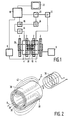
- a magnetic resonance apparatus as shown in Fig. 1 comprises a superconductive magnet system 2 for generating a stationary magnetic field, magnet coils 4 for generating a gradient field, a supply source 6 for the magnet system 2 and a supply source 8 for the gradient coil 4.
- An rf coil system 10 serves, for example, both for generating a radio frequency pulsated magnet field and for detecting nuclear magnetic resonance generated in an object to be measured by the radio frequency field.
- Upon transmitting the rf coil system 10 is connected to a radio frequency source 12.
- a detection amplifier 14 During detecting the coil system 10 is connected to a detection amplifier 14.
- the amplifier 14 is connected to a rectifier 16 which is connected to a central control device 18.
- the central control device 18 further controls a modulator 20 for the radio frequency source 12, the supply source 8 for the gradient field and a monitor 22 for imaging.
- a high frequency oscillator 24 controls both the modulator 20 for the radio frequency source 12 and the phace-sensitive rectifier 16 processing the measured signals.
- Fig. 2 shows a magnet system 2 in its simplest form consisting of a single cylinder 30 of a superconductive material.
- a cylinder has a diameter of, for example, 1.0 metre and a length of, for example 1.2 metre.
- the superconductive material forms a closed cylinder surface 34. Because it is often difficult to form a self-supporting cylinder from superconductive material first a carrier cylinder 36 has been formed for making the coil, for example, of metal, but also of ceramic material or a synthetic resin.
- the wall thickness of the supporting cylinder is, for example, a few millimetres and the thickness of the superconductive material is uniform over the whole cylinder surface, or, viewed in the axial direction, varies locally, adapted to a maximum permissible superconductive current density with a safety margin therebelow.
- the superconductive material In order to prevent field influencing by the carrier in a measuring space 28 as much as possible it is favourable to provide the superconductive material on an inside of the supporting cylinder, but this is not necessary also dependent on the selective carrier material. It may also be favourable to provide a layer of a superconductive material on both surfaces of the carrier cylinder.
- the carrier cylinder may also have the function of a cold conductor, for example, for more rapid and more uniform cooling or heating the superconducting material, but may also serve as a thermal insulator, for example, when it is desired in a double coating that one of the two superconductive cylinders is temporarily superconductive and the other one is not yet superconductive.
- This situation can also be realised by using cylinders of a superconductive material with mutually different transition temperatures.
- quenching it is favourable for the current density in the superconductive material to be uniform.
- the uniformity in the current density can be optimised by adapting the thickness. If the quenching temperature locally drops as a result of, for example, the strength of a locally present magnetic field, this may also be taken into account by varying the thickness.
- an auxiliary coil 38 may be used which in fact does not form part of the magnet system but only has the function of activation.
- the auxiliary coil 38 is provided in or around the magnetic field cylinder 30 and is then activated in such a manner that a desired magnetic field B enclosed by the cylinder is generated.
- the superconductive magnetic field cylinder or cylinders is or are then cooled to the superconductive state after which the auxiliary coil is removed.
- the magnetic field B has now been frozen-in by the superconductive magnetic field cylinder and is maintained therein by persisting circular currents in the cylinder surface.
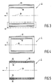
- a magnet system 2 as shown in Fig. 3 again comprises a superconductive magnetic field cylinder 30.
- a superconductive screening cylinder 40 by means of which a stray field 42 of the magnetic field cylinder between the two cylinders is bundled, so that the space outside the two cylinders can be made substantially stray field arm and the extent of the stray field in the axial direction is also reduced.
- the magnet system shown in Fig. 3 is also incorporated in a thermally insulating housing 44 which is shown diagrammatically in the drawing and encloses the magnet system cylindrically in such a manner that the measuring space 28 remains free and accessible.
- a cooling to, for example, approximately 100 K will suffice so that, for example, liquid nitrogen may be used and the cooling system may be very simple, compact and cheap. Cooling may then be carried out in a comparatively simple manner with, for example, a cooling machine having a thermally insulated good thermal conductivity towards the superconductive material or by a gas or liquid flow circulating therefrom. For materials which only become superconductive above room temperature, the magnet system in the housing 44 may be heated before providing in the non-superconductive state.
- Fig. 4 shows an embodiment of a magnet system 2 in which a superconductive stabilising cylinder 50 is incorporated within the field cylinder 30.
- the advantage of a stabilisation cylinder is that variations in the persisting currents in the magnetic field cylinder can be compensated thereby, for example, the slow decrease of the field cylinder current by an occurring residual resistance or by local quenching. Corrections may also be made in the field of the field cylinder by means of the stabilisation cylinder, this both for inhomogeneities in the persisting currents therein and for wrongly frozen-in fields.
- a further practical advantage is that the field cylinder can now be loaded comparatively high since some drift in the persisting current is permissible and complementary currents need not be incorporated.
- the stabilising superconductive cylinder may again be placed in the field cylinder as a self-supporting cylinder or in the form of a surface coating on a carrier cylinder.
- the stabilisation cylinder may also be formed by an already mentioned inner surface coating of the cylinder 30.
- the systems according to Figs. 3 and 4 are combined to form a screening stabilised magnetic system thus having three superconductive cylinders.
- An embodiment as shown in Fig. 5 comprises a magnet system 2 having one or more superconductive cylinders 60 built up from flat rings 62 each consisting of a carrier 64 coated on each side with a layer of superconductive material 66 but which may of course also be covered on one side only. More superconductive material may be incorporated over the same axial length as a result of which superconductive material having a comparatively low maximum permissible current density may also be used and on the other hand superconductive material which can be provided only in comparatively thin layers may also be used. To be considered are rings which are to be made individually and are then to be stacked but a cylinder constructed from superconductive material alternated by carrier material provided on a starter ring may also be considered.
- a magnetic field cylinder 60 as shown may again form a magnetic system as shown in Fig. 2 but these cylinders may also form part of magnetic systems as shown in Figs. 3 and 4.
- the current density for the superconductive material may be uniformed by thickness variations measured in the axial direction or be adapted to local field strength.
- the latter may now also be realised by varying the axial thickness of the carrier rings or the superconductive rings or both in the axial direction of the cylinder as is shown in a lower side of Fig. 5 as a result of which an axial locally varying cross-section of superconductive material has again been realised.
- the stabilisation cylinder is made superconductive only when the measuring coils measure a correct field distribution. By making the stabilisation cylinder superconductive the correct field is then frozen-in.
- the stabilisation cylinder may also be of use to avoid field disturbances as a result of eddy currents which might be generated by gradient coils to be added to the magnet system. With the field correction the compensation currents necessary therefore may be taken into account because they are no longer time dependent as persistent currents.
Landscapes
- Physics & Mathematics (AREA)
- Health & Medical Sciences (AREA)
- Epidemiology (AREA)
- Condensed Matter Physics & Semiconductors (AREA)
- General Physics & Mathematics (AREA)
- Magnetic Resonance Imaging Apparatus (AREA)
Applications Claiming Priority (2)
| Application Number | Priority Date | Filing Date | Title |
|---|---|---|---|
| NL8801162A NL8801162A (nl) | 1988-05-04 | 1988-05-04 | Supergeleidend magneetstelsel met supergeleidende cylinders. |
| NL8801162 | 1988-05-04 |
Publications (2)
| Publication Number | Publication Date |
|---|---|
| EP0340860A1 true EP0340860A1 (de) | 1989-11-08 |
| EP0340860B1 EP0340860B1 (de) | 1994-07-06 |
Family
ID=19852249
Family Applications (1)
| Application Number | Title | Priority Date | Filing Date |
|---|---|---|---|
| EP89201104A Expired - Lifetime EP0340860B1 (de) | 1988-05-04 | 1989-04-28 | Supraleitendes Magnetsystem mit supraleitenden Zylindern |
Country Status (6)
| Country | Link |
|---|---|
| US (1) | US4931735A (de) |
| EP (1) | EP0340860B1 (de) |
| JP (1) | JPH0217478A (de) |
| DE (1) | DE68916584T2 (de) |
| IL (1) | IL90156A0 (de) |
| NL (1) | NL8801162A (de) |
Cited By (7)
| Publication number | Priority date | Publication date | Assignee | Title |
|---|---|---|---|---|
| EP0488464A1 (de) * | 1990-11-30 | 1992-06-03 | Koninklijke Philips Electronics N.V. | Kernspinresonanzapparat mit einem supraleitenden Abschirmmagneten |
| EP0562708A1 (de) * | 1992-03-27 | 1993-09-29 | Picker International, Inc. | Anordnungen von supraleitenden Magneten |
| EP0681189A1 (de) * | 1994-05-02 | 1995-11-08 | General Electric Company | Supraleitende Abschirmungen für Gradienten-Spulen bei Magneten zur Bilderzeugung mittels magnetischer Resonanz |
| EP0730284A1 (de) * | 1995-02-28 | 1996-09-04 | Hitachi, Ltd. | Durch laminieren von Leitenplattern mit Hohlprofil hergestellten supraleitender Magnet |
| EP0797261A1 (de) * | 1996-03-22 | 1997-09-24 | International Superconductivity Technology Center | Supraleitendes Materialgemisch |
| EP1978373A1 (de) * | 2007-04-06 | 2008-10-08 | Kabushiki Kaisha Toshiba | Gradientenabschirmspule für eine Magnetresonanzbildgebungsvorrichtung |
| DE102008037507B4 (de) * | 2007-10-31 | 2012-02-16 | General Electric Company | Magnetanordnung für eine Magnetresonanz-Bildgebungsvorrichtung |
Families Citing this family (12)
| Publication number | Priority date | Publication date | Assignee | Title |
|---|---|---|---|---|
| US5187327A (en) * | 1989-09-29 | 1993-02-16 | Mitsui Kinzoku Kogyo Kabushiki Kaisha | Superconducting magnetic shield |
| GB9016184D0 (en) * | 1990-07-24 | 1990-09-05 | Oxford Magnet Tech | Magnet assembly |
| US5596303A (en) * | 1993-02-22 | 1997-01-21 | Akguen Ali | Superconductive magnet system with low and high temperature superconductors |
| US5633588A (en) * | 1994-09-16 | 1997-05-27 | Hitachi Medical Corporation | Superconducting magnet apparatus using superconducting multilayer composite member, method of magnetizing the same and magnetic resonance imaging system employing the same |
| US5764121A (en) * | 1995-11-08 | 1998-06-09 | Intermagnetics General Corporation | Hybrid high field superconducting assembly and fabrication method |
| US6097187A (en) * | 1997-08-21 | 2000-08-01 | Picker International, Inc. | MRI magnet with fast ramp up capability for interventional imaging |
| DE10157972B4 (de) * | 2001-11-27 | 2004-01-08 | Bruker Biospin Ag | NMR-Spektrometer und Betriebsverfahren mit Stabilisierung der transversalen Magnetisierung bei supraleitenden NMR-Resonatoren |
| US7098663B1 (en) * | 2005-03-18 | 2006-08-29 | Timothy James Hollis | Systems, methods and apparatus of an actively shielded superconducting magnet drift compensation coil |
| JP4610449B2 (ja) * | 2005-09-01 | 2011-01-12 | 株式会社日立製作所 | 磁石装置 |
| JP5143006B2 (ja) * | 2005-10-03 | 2013-02-13 | マサチューセッツ インスティテュート オブ テクノロジー | 磁気の共鳴スペクトルを得るための輪状磁石を使ったシステム |
| US7656242B2 (en) * | 2006-11-07 | 2010-02-02 | Joseph J. Boyd | Electromagnetic electric generator |
| JP2012143661A (ja) * | 2012-05-11 | 2012-08-02 | Toshiba Corp | 磁気共鳴イメージング装置、シールドコイル、シールドコイルの製造方法、及び、磁気共鳴イメージング装置の駆動方法 |
Citations (6)
| Publication number | Priority date | Publication date | Assignee | Title |
|---|---|---|---|---|
| US3370258A (en) * | 1965-12-10 | 1968-02-20 | Gen Electric Co Ltd | Methods of and apparatus for the production of magnetic fields using superconductingmagnets |
| US3486146A (en) * | 1967-09-22 | 1969-12-23 | Atomic Energy Commission | Superconductor magnet and method |
| US4409579A (en) * | 1982-07-09 | 1983-10-11 | Clem John R | Superconducting magnetic shielding apparatus and method |
| DE3301630A1 (de) * | 1983-01-19 | 1984-07-19 | Siemens AG, 1000 Berlin und 8000 München | Geraet zur erzeugung von bildern eines untersuchungsobjektes |
| EP0138270A2 (de) * | 1983-10-14 | 1985-04-24 | Koninklijke Philips Electronics N.V. | Magnetischer Kernresonanzapparat |
| DE3344047A1 (de) * | 1983-12-06 | 1985-06-13 | BBC Aktiengesellschaft Brown, Boveri & Cie., Baden, Aargau | Magnetsystem fuer einen kernspintomograph |
Family Cites Families (8)
| Publication number | Priority date | Publication date | Assignee | Title |
|---|---|---|---|---|
| US4642569A (en) * | 1983-12-16 | 1987-02-10 | General Electric Company | Shield for decoupling RF and gradient coils in an NMR apparatus |
| NL8402250A (nl) * | 1984-07-17 | 1986-02-17 | Philips Nv | Kernspin resonantie apparaat met een rechthoekig permanent magnetische magneet. |
| US4636730A (en) * | 1984-08-16 | 1987-01-13 | General Electric Company | NMR spectroscopy body probes with at least one surface coil |
| FR2583172B1 (fr) * | 1985-06-07 | 1987-11-20 | Thomson Cgr | Antenne haute frequence pour appareil mesurant la resonance magnetique nucleaire |
| US4689563A (en) * | 1985-06-10 | 1987-08-25 | General Electric Company | High-field nuclear magnetic resonance imaging/spectroscopy system |
| US4694254A (en) * | 1985-06-10 | 1987-09-15 | General Electric Company | Radio-frequency spectrometer subsystem for a magnetic resonance imaging system |
| JPS63316408A (ja) * | 1987-06-18 | 1988-12-23 | Yokogawa Medical Syst Ltd | 超電導電磁石及びその着磁方法 |
| JPH0738333B2 (ja) * | 1987-07-03 | 1995-04-26 | 三菱電機株式会社 | 磁界発生装置 |
-
1988
- 1988-05-04 NL NL8801162A patent/NL8801162A/nl not_active Application Discontinuation
-
1989
- 1989-04-28 EP EP89201104A patent/EP0340860B1/de not_active Expired - Lifetime
- 1989-04-28 DE DE68916584T patent/DE68916584T2/de not_active Expired - Fee Related
- 1989-05-02 US US07/347,599 patent/US4931735A/en not_active Expired - Fee Related
- 1989-05-02 IL IL90156A patent/IL90156A0/xx unknown
- 1989-05-06 JP JP1114008A patent/JPH0217478A/ja active Pending
Patent Citations (6)
| Publication number | Priority date | Publication date | Assignee | Title |
|---|---|---|---|---|
| US3370258A (en) * | 1965-12-10 | 1968-02-20 | Gen Electric Co Ltd | Methods of and apparatus for the production of magnetic fields using superconductingmagnets |
| US3486146A (en) * | 1967-09-22 | 1969-12-23 | Atomic Energy Commission | Superconductor magnet and method |
| US4409579A (en) * | 1982-07-09 | 1983-10-11 | Clem John R | Superconducting magnetic shielding apparatus and method |
| DE3301630A1 (de) * | 1983-01-19 | 1984-07-19 | Siemens AG, 1000 Berlin und 8000 München | Geraet zur erzeugung von bildern eines untersuchungsobjektes |
| EP0138270A2 (de) * | 1983-10-14 | 1985-04-24 | Koninklijke Philips Electronics N.V. | Magnetischer Kernresonanzapparat |
| DE3344047A1 (de) * | 1983-12-06 | 1985-06-13 | BBC Aktiengesellschaft Brown, Boveri & Cie., Baden, Aargau | Magnetsystem fuer einen kernspintomograph |
Non-Patent Citations (1)
| Title |
|---|
| REVIEW OF SCIENTIFIC INSTRUMENTS, vol. 53, no. 4, April 1982, pages 485-490, American Institute of Physics, New York, US; K.A. MUETHING et al.: "Small solenoid with a superconducting shield for nuclear-magnetic-resonance near 1 mK" * |
Cited By (12)
| Publication number | Priority date | Publication date | Assignee | Title |
|---|---|---|---|---|
| EP0488464A1 (de) * | 1990-11-30 | 1992-06-03 | Koninklijke Philips Electronics N.V. | Kernspinresonanzapparat mit einem supraleitenden Abschirmmagneten |
| EP0562708A1 (de) * | 1992-03-27 | 1993-09-29 | Picker International, Inc. | Anordnungen von supraleitenden Magneten |
| US5289128A (en) * | 1992-03-27 | 1994-02-22 | Picker International, Inc. | Superconducting gradient shield coils |
| EP0681189A1 (de) * | 1994-05-02 | 1995-11-08 | General Electric Company | Supraleitende Abschirmungen für Gradienten-Spulen bei Magneten zur Bilderzeugung mittels magnetischer Resonanz |
| EP0730284A1 (de) * | 1995-02-28 | 1996-09-04 | Hitachi, Ltd. | Durch laminieren von Leitenplattern mit Hohlprofil hergestellten supraleitender Magnet |
| US5812042A (en) * | 1995-02-28 | 1998-09-22 | Hitachi, Ltd. | Superconducting magnet formed by laminating hollow conductor plates |
| EP0797261A1 (de) * | 1996-03-22 | 1997-09-24 | International Superconductivity Technology Center | Supraleitendes Materialgemisch |
| US5920246A (en) * | 1996-03-22 | 1999-07-06 | International Superconductivity Technolgy Center | Superconductive composite materials |
| EP1978373A1 (de) * | 2007-04-06 | 2008-10-08 | Kabushiki Kaisha Toshiba | Gradientenabschirmspule für eine Magnetresonanzbildgebungsvorrichtung |
| US7777489B2 (en) | 2007-04-06 | 2010-08-17 | Kabushiki Kaisha Toshiba | Magnetic resonance imaging apparatus, shield coil, manufacturing method of shield coil, and driving method of magnetic resonance imaging apparatus |
| CN101281240B (zh) * | 2007-04-06 | 2012-07-04 | 株式会社东芝 | 磁共振成像装置及其驱动方法、屏蔽线圈及其制造方法 |
| DE102008037507B4 (de) * | 2007-10-31 | 2012-02-16 | General Electric Company | Magnetanordnung für eine Magnetresonanz-Bildgebungsvorrichtung |
Also Published As
| Publication number | Publication date |
|---|---|
| US4931735A (en) | 1990-06-05 |
| DE68916584D1 (de) | 1994-08-11 |
| IL90156A0 (en) | 1989-12-15 |
| NL8801162A (nl) | 1989-12-01 |
| DE68916584T2 (de) | 1995-02-09 |
| EP0340860B1 (de) | 1994-07-06 |
| JPH0217478A (ja) | 1990-01-22 |
Similar Documents
| Publication | Publication Date | Title |
|---|---|---|
| US4931735A (en) | Superconductive magnet system comprising superconductive cylinders | |
| US4876510A (en) | Apparatus for nuclear spin tomography having superconducting base field magnetic coils and a radiation shield | |
| EP0350262B1 (de) | Stützvorrichtung einer Strahlungsabschirmung in einem Magnetresonanz-Magneten | |
| US4176291A (en) | Stored field superconducting electrical machine and method | |
| JP2609295B2 (ja) | 核磁気共鳴断層像装置の超伝導磁石 | |
| JPH0335815B2 (de) | ||
| EP0350263B1 (de) | Kabelaufhängungssytem für zylindrische Gefässe | |
| JPH0561762B2 (de) | ||
| JPH0670907A (ja) | 磁気共鳴装置及び方法 | |
| CA1280153C (en) | Conical unimpregnated winding for mr magnets | |
| JPH07142237A (ja) | 超電導磁石装置 | |
| US20140066312A1 (en) | Magnet system for generation of a highly stable magnetic field | |
| JP6636405B2 (ja) | Lts部分とhts部分を有するマグネット装置を備えるクライオスタット | |
| US6727699B2 (en) | Superconducting magnet system | |
| US4180769A (en) | Superconducting solenoid with compensation for axial gradients | |
| KR101916440B1 (ko) | 유도성-저항성 전류 제한을 위한 전기 코일 시스템 | |
| JP2022003681A (ja) | 軸方向積層バルク副磁石の個々の温度制御を伴う超伝導磁石システム | |
| JPH0335818B2 (de) | ||
| US4213092A (en) | NMR Spectrometer with superconducting coil having rectangular cross-section wire | |
| US7365540B2 (en) | Hybrid magnet configuration | |
| US3200299A (en) | Superconducting electromagnet | |
| US4833433A (en) | Magnet system for nuclear spin tomography having superconducting coils and a cold shield | |
| Morimoto et al. | Measurements of Pfirsch-Schlüter current and pressure profile for the high density ECH plasmas in Heliotron DR | |
| USRE31895E (en) | NMR spectrometer with superconducting coil having rectangular cross-section wire | |
| JPH0838454A (ja) | 磁気共鳴映像装置の磁石 |
Legal Events
| Date | Code | Title | Description |
|---|---|---|---|
| PUAI | Public reference made under article 153(3) epc to a published international application that has entered the european phase |
Free format text: ORIGINAL CODE: 0009012 |
|
| AK | Designated contracting states |
Kind code of ref document: A1 Designated state(s): DE FR GB IT |
|
| 17P | Request for examination filed |
Effective date: 19900504 |
|
| 17Q | First examination report despatched |
Effective date: 19910729 |
|
| GRAA | (expected) grant |
Free format text: ORIGINAL CODE: 0009210 |
|
| AK | Designated contracting states |
Kind code of ref document: B1 Designated state(s): DE FR GB IT |
|
| PG25 | Lapsed in a contracting state [announced via postgrant information from national office to epo] |
Ref country code: IT Free format text: LAPSE BECAUSE OF FAILURE TO SUBMIT A TRANSLATION OF THE DESCRIPTION OR TO PAY THE FEE WITHIN THE PRESCRIBED TIME-LIMIT;WARNING: LAPSES OF ITALIAN PATENTS WITH EFFECTIVE DATE BEFORE 2007 MAY HAVE OCCURRED AT ANY TIME BEFORE 2007. THE CORRECT EFFECTIVE DATE MAY BE DIFFERENT FROM THE ONE RECORDED. Effective date: 19940706 |
|
| REF | Corresponds to: |
Ref document number: 68916584 Country of ref document: DE Date of ref document: 19940811 |
|
| ET | Fr: translation filed | ||
| PLBE | No opposition filed within time limit |
Free format text: ORIGINAL CODE: 0009261 |
|
| STAA | Information on the status of an ep patent application or granted ep patent |
Free format text: STATUS: NO OPPOSITION FILED WITHIN TIME LIMIT |
|
| REG | Reference to a national code |
Ref country code: FR Ref legal event code: CD |
|
| 26N | No opposition filed | ||
| PGFP | Annual fee paid to national office [announced via postgrant information from national office to epo] |
Ref country code: GB Payment date: 19970401 Year of fee payment: 9 |
|
| PGFP | Annual fee paid to national office [announced via postgrant information from national office to epo] |
Ref country code: FR Payment date: 19970422 Year of fee payment: 9 |
|
| PGFP | Annual fee paid to national office [announced via postgrant information from national office to epo] |
Ref country code: DE Payment date: 19970624 Year of fee payment: 9 |
|
| PG25 | Lapsed in a contracting state [announced via postgrant information from national office to epo] |
Ref country code: GB Free format text: LAPSE BECAUSE OF NON-PAYMENT OF DUE FEES Effective date: 19980428 |
|
| PG25 | Lapsed in a contracting state [announced via postgrant information from national office to epo] |
Ref country code: FR Free format text: THE PATENT HAS BEEN ANNULLED BY A DECISION OF A NATIONAL AUTHORITY Effective date: 19980430 |
|
| GBPC | Gb: european patent ceased through non-payment of renewal fee |
Effective date: 19980428 |
|
| PG25 | Lapsed in a contracting state [announced via postgrant information from national office to epo] |
Ref country code: DE Free format text: LAPSE BECAUSE OF NON-PAYMENT OF DUE FEES Effective date: 19990202 |
|
| REG | Reference to a national code |
Ref country code: FR Ref legal event code: ST |