EP0488464A1 - Kernspinresonanzapparat mit einem supraleitenden Abschirmmagneten - Google Patents
Kernspinresonanzapparat mit einem supraleitenden Abschirmmagneten Download PDFInfo
- Publication number
- EP0488464A1 EP0488464A1 EP91203063A EP91203063A EP0488464A1 EP 0488464 A1 EP0488464 A1 EP 0488464A1 EP 91203063 A EP91203063 A EP 91203063A EP 91203063 A EP91203063 A EP 91203063A EP 0488464 A1 EP0488464 A1 EP 0488464A1
- Authority
- EP
- European Patent Office
- Prior art keywords
- magnet
- coil system
- coil
- superconducting
- shielding
- Prior art date
- Legal status (The legal status is an assumption and is not a legal conclusion. Google has not performed a legal analysis and makes no representation as to the accuracy of the status listed.)
- Granted
Links
- 230000004907 flux Effects 0.000 claims abstract description 6
- 238000005259 measurement Methods 0.000 claims description 6
- 230000004913 activation Effects 0.000 claims description 2
- 239000000463 material Substances 0.000 claims description 2
- 230000000694 effects Effects 0.000 description 4
- 238000003384 imaging method Methods 0.000 description 4
- 230000006698 induction Effects 0.000 description 4
- 239000004020 conductor Substances 0.000 description 3
- 238000004804 winding Methods 0.000 description 3
- 230000008878 coupling Effects 0.000 description 2
- 238000010168 coupling process Methods 0.000 description 2
- 238000005859 coupling reaction Methods 0.000 description 2
- 230000001419 dependent effect Effects 0.000 description 2
- 238000001514 detection method Methods 0.000 description 2
- 230000005672 electromagnetic field Effects 0.000 description 2
- 230000001939 inductive effect Effects 0.000 description 2
- 238000000034 method Methods 0.000 description 2
- 230000002085 persistent effect Effects 0.000 description 2
- 230000008569 process Effects 0.000 description 2
- 238000010791 quenching Methods 0.000 description 2
- 230000000171 quenching effect Effects 0.000 description 2
- 230000006978 adaptation Effects 0.000 description 1
- 230000002411 adverse Effects 0.000 description 1
- 230000004323 axial length Effects 0.000 description 1
- 230000008859 change Effects 0.000 description 1
- 239000002131 composite material Substances 0.000 description 1
- 230000002035 prolonged effect Effects 0.000 description 1
- 238000004611 spectroscopical analysis Methods 0.000 description 1
- 239000002887 superconductor Substances 0.000 description 1
- 230000001629 suppression Effects 0.000 description 1
- 238000003325 tomography Methods 0.000 description 1
Images
Classifications
-
- G—PHYSICS
- G01—MEASURING; TESTING
- G01R—MEASURING ELECTRIC VARIABLES; MEASURING MAGNETIC VARIABLES
- G01R33/00—Arrangements or instruments for measuring magnetic variables
- G01R33/20—Arrangements or instruments for measuring magnetic variables involving magnetic resonance
- G01R33/28—Details of apparatus provided for in groups G01R33/44 - G01R33/64
- G01R33/42—Screening
- G01R33/421—Screening of main or gradient magnetic field
Definitions
- the invention relates to a magnetic resonance apparatus, comprising a superconducting magnet coil system for generating a steady magnetic field in a measurement space within the magnet and also comprising a superconducting shielding coil system which is arranged so as to be coaxial with the steady field magnet coil system.
- a superconducting magnet coil system of this kind is known from EP 138 270.
- the cited publication discloses a magnet coil system which is composed of superconducting coils and which comprises, notably for active self-shielding, two coaxially arranged coil systems which are to be activated with opposite polarity.
- the invention is inter alia based on the recognition of the fact that superconducting MR magnets are customarily used in the so-called persistent mode where the magnet is short-circuited in itself and, if the magnet coil circuit is suitably superconducting, current and field will remain very stable over a prolonged period of time.
- a magnet thus short-circuited is exposed to a varying, externally generated magnetic field, for example originating from a moving magnetized object or resulting from a varying electric current, the total magnetic flux enclosed by the magnet will remain constant.
- the external field causes a magnetic flux in the magnet, the current in the magnet will change so that the variation of the flux within the magnet will be equal but opposed to the external magnetic flux.
- a current variation causes a field variation whose extent is co-determined by a coil constant of the magnet. This field variation is generally opposed to the external field variation.
- US-A-4,974,113 discloses a coil system which aims to reduce the effect of external field variations on the measurement field homogeneity, but this solution leads to a comparatively long coil system.
- a magnetic resonance apparatus of the kind set forth in accordance with the invention is characterized in that the shielding coil system comprises coil sections of different diameter.
- the composite magnet coil system is shielded against said magnetic field variations in that an adapted opposing field is generated in the shielding coil.
- the shielding coil system notably forms a superconducting coil conductor circuit which is short-circuited in itself for persistent current conduction. Fully automatic shielding can thus be realised.
- the shielding coil system notably comprises coils with arc conductor sections with two different diameters. In order to eliminate induced gradient field variations, it may be attractive to connect coils, for example symmetrically arranged with respect to the axial symmetry plane, so as to be activatable with opposite polarity.
- the magnet coil and the shielding magnet coils together constitute a magnet coil system incorporating substantially complete shielding against external magnetic field variations. External magnetic field variations cannot induce internal field variations in a magnet coil system of this kind.
- a shielding coil system may be constructed as a solenoid which is short-circuited in itself, but it may also be constructed, for example as a stack of superconducting rings or as a single cylinder made of a superconducting material as described in US-A-4,931,735.
- a solenoid When used as a shielding magnet coil, a solenoid will become comparatively long with respect to the magnet coil when optimum shielding is to be achieved.
- a shorter shielding coil system can be realised in a preferred embodiment in that two series-connected, coaxially arranged coils of mutually different diameter are included.
- a shielding factor which is strongly dependent on the geometry of the coil can be assigned to a magnet coil system.
- a superconducting MR magnet may consist of, for example six coaxial coil sections of the same diameter which have a geometry such that the field is uniform up to the 12 th order and have a shielding factor of approximately 0.75, which value is dependent on, for example the width of the coil sections. This means that with the magnet the effect of an external field variation is reduced by induction to approximately one quarter of that outside the magnet.
- the aforementioned class of magnets with active stray field compensation constitute a special case.
- the superconducting circuit then consists of coil sections having two different diameters, the coils of the greatest diameter having an opposed polarity.
- One requirement to be satisfied so as to achieve suitable own stray field suppression consists in that the magnetic dipole moment must be substantially zero.
- the shielding factor, being proportional thereto, thus also becomes substantially zero.
- An actively shielded superconducting magnet therefore, has no significant compensating effect as regards external field variations.
- a preferred embodiment of the shielding coil system comprises three pairs of coil sections with two different diameters.
- Optimum shielding can thus be combined with, for example due to the configuration of the winding, a high degree of field homogeneity for the shielded magnet system.
- the shielding coil system is notably coaxial and mirror-symmetrical with respect to an axial central plane and comprises coil sections of mutually the same polarity with diameters adapted to coil sections of the magnet coil system.
- shielding coil systems can be realised which can be mounted in a common Dewar vessel, preferably on supports for coil sections of the steady magnet coil system, their length in any case not being substantially greater than that of the main magnet.
- the shielding and the field homogeneity can be optimized.
- actively shielded magnet systems make the use of shielding coil sections of mutually different diameter comparatively simple by adaptation of diameters to inner or outer diameters of the two coil systems thereof.
- superconducting switches are included in the shielding coil circuit in order to prevent high current intensities in shielding coils, for example due to quenching or upon activation of the magnet etc.
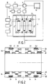
- a magnetic resonance apparatus as shown in Fig. 1 comprises a steady field magnet with an electromagnetic coil system 1 which comprises, for example from four to eight coils 2 for generating a strong, steady, uniform magnetic field in a measurement space 3 within the coil system.
- an electromagnetic coil system 1 which comprises, for example from four to eight coils 2 for generating a strong, steady, uniform magnetic field in a measurement space 3 within the coil system.
- MR imaging pp. 121-123.
- gradient coils 4 For the use as a magnetic resonance tomography apparatus, i.e. an apparatus for the slice-wise imaging of an object, to be described hereinafter use is made of gradient coils 4.
- the gradient coils can be dispensed with.
- RF coils 5 are arranged comparatively closely around the measurement space, which RF coils serve as transmitter coils for an RF electromagnetic field and as a detection coil for spin resonance signals thus generated. It is alternatively possible to use separate coils for these two functions.
- Spin resonance signals stimulated by the RF electromagnetic field in an object to be measured are picked up via a signal amplifier 6 and applied, via a phase-sensitive amplifier 8, to a central arithmetic and control device 10.
- a modulator 12 for an RF supply source 14 a supply source 16 for the main field magnet coils, a supply source 17 for the gradient coils, an RF oscillator 18, and a monitor 20 for image display.
- the oscillator 18 controls the modulator 12 for the RF fields as well as the phase-sensitive amplifier 8 which processes the measurement signals.
- a shielding coil system 22 with a control device 25 is arranged concentrically around or in the steady field magnet coil system.
- the shielding coil system in this case adapted to a steady field magnet system with active own shielding, comprises three pairs of coil sections 24, an inner pair 241 and an outer pair 243, viewed in the axial direction, of which are mounted on a coil former for a first magnet coil system 26 of the main magnet 1, a central pair 242 being arranged on a coil former for a second magnet coil system 28 of the main magnet 1.
- the shielding and the field homogeneity can be optimized notably by way of the axial length and the winding configuration of the coil pair 241.
- a length-to-diameter ratio of 0.875 is unpractical for a practical MR magnet.
- a substantially shorter coil system having the shielding factor 1 is obtained by utilizing two coaxial coils of different diameter, which coils together constitute a closed superconducting circuit. It is desirable to design the shielding coil system so that a high field homogeneity is achieved within the coil. Such a high homogeneity is desirable because, in the event of poor homogeneity the shielding factor outside the isocentre will not be equal to that in the isocentre; this difference may not become excessively large.
Landscapes
- Physics & Mathematics (AREA)
- Health & Medical Sciences (AREA)
- Epidemiology (AREA)
- Condensed Matter Physics & Semiconductors (AREA)
- General Physics & Mathematics (AREA)
- Magnetic Resonance Imaging Apparatus (AREA)
Applications Claiming Priority (2)
| Application Number | Priority Date | Filing Date | Title |
|---|---|---|---|
| NL9002621 | 1990-11-30 | ||
| NL9002621A NL9002621A (nl) | 1990-11-30 | 1990-11-30 | Magnetisch resonantie apparaat met afschermende magneet. |
Publications (2)
| Publication Number | Publication Date |
|---|---|
| EP0488464A1 true EP0488464A1 (de) | 1992-06-03 |
| EP0488464B1 EP0488464B1 (de) | 1999-10-13 |
Family
ID=19858059
Family Applications (1)
| Application Number | Title | Priority Date | Filing Date |
|---|---|---|---|
| EP91203063A Expired - Lifetime EP0488464B1 (de) | 1990-11-30 | 1991-11-22 | Kernspinresonanzapparat mit einem supraleitenden Abschirmmagneten |
Country Status (5)
| Country | Link |
|---|---|
| US (1) | US5235282A (de) |
| EP (1) | EP0488464B1 (de) |
| JP (1) | JP3043494B2 (de) |
| DE (1) | DE69131708T2 (de) |
| NL (1) | NL9002621A (de) |
Cited By (4)
| Publication number | Priority date | Publication date | Assignee | Title |
|---|---|---|---|---|
| EP0727672A1 (de) * | 1995-02-14 | 1996-08-21 | Kabushiki Kaisha Toshiba | Magnet zur Erzeugung des statischen Magnetfeldes in einem System der Bilderzeugung mittels magnetischer Resonanz mit einer aktiven magnetischen Abschirmung |
| EP1065512A3 (de) * | 1999-07-02 | 2003-03-12 | Bruker BioSpin AG | Aktiv abgeschirmte supraleitende Magnetanordnung mit Feldstörungskompensation |
| EP1361453A1 (de) * | 2002-05-08 | 2003-11-12 | Hitachi, Ltd. | NMR-Magnet für Lösungsanalyse und NMR-Gerät |
| US7170291B2 (en) | 2003-11-22 | 2007-01-30 | Bruker Biospin Gmbh | Additional fringe field shield for a superconducting magnet coil system |
Families Citing this family (12)
| Publication number | Priority date | Publication date | Assignee | Title |
|---|---|---|---|---|
| NL9002621A (nl) | 1990-11-30 | 1992-06-16 | Koninkl Philips Electronics Nv | Magnetisch resonantie apparaat met afschermende magneet. |
| US5426366A (en) * | 1992-12-11 | 1995-06-20 | U.S. Philips Corporation | Magnetic resonance apparatus comprising a superconducting magnet |
| US5635839A (en) * | 1994-11-04 | 1997-06-03 | Picker International, Inc. | High order passive shimming assembly for MRI magnets |
| US6097187A (en) * | 1997-08-21 | 2000-08-01 | Picker International, Inc. | MRI magnet with fast ramp up capability for interventional imaging |
| US7046005B2 (en) * | 2003-12-22 | 2006-05-16 | General Electric Company | Method and apparatus for driver circuits for use in magnetic systems |
| US7064550B2 (en) * | 2004-11-16 | 2006-06-20 | General Electric Company | Method and apparatus for field drift compensation of a superconducting magnet |
| JP4610449B2 (ja) | 2005-09-01 | 2011-01-12 | 株式会社日立製作所 | 磁石装置 |
| JP4928477B2 (ja) * | 2008-01-23 | 2012-05-09 | 株式会社日立製作所 | 超電導磁石装置、およびこれを用いた磁気共鳴イメージング装置、並びに核磁気共鳴装置 |
| DE102009004899B4 (de) * | 2009-01-16 | 2015-09-24 | Siemens Aktiengesellschaft | Supraleitender aktiv geschirmter Magnet |
| FR2975497B1 (fr) * | 2011-05-16 | 2013-06-28 | Centre Nat Rech Scient | Convertisseur electronique de puissance |
| DE102012203331B4 (de) * | 2012-03-02 | 2015-08-27 | Siemens Aktiengesellschaft | Lokalschirm und Verfahren zur Abschirmung von Magnetresonanzsignalen |
| WO2020155137A1 (en) | 2019-02-02 | 2020-08-06 | Shanghai United Imaging Healthcare Co., Ltd. | Radiation therapy system and method |
Citations (5)
| Publication number | Priority date | Publication date | Assignee | Title |
|---|---|---|---|---|
| EP0139308A2 (de) * | 1983-10-14 | 1985-05-02 | Koninklijke Philips Electronics N.V. | Magnetischer Kernresonanzapparat |
| US4658229A (en) * | 1985-05-10 | 1987-04-14 | Ga Technologies Inc. | Magnet system providing a region of substantially homogeneous field strength |
| US4812797A (en) * | 1988-03-22 | 1989-03-14 | General Electric Company | Compensation coil for temporal drift of a superconducting magnet |
| WO1989009475A1 (en) * | 1988-03-16 | 1989-10-05 | President And Fellows Of Harvard College | Shielding superconducting solenoids |
| EP0340860A1 (de) * | 1988-05-04 | 1989-11-08 | Koninklijke Philips Electronics N.V. | Supraleitendes Magnetsystem mit supraleitenden Zylindern |
Family Cites Families (9)
| Publication number | Priority date | Publication date | Assignee | Title |
|---|---|---|---|---|
| NL8303533A (nl) * | 1983-10-14 | 1985-05-01 | Koninkl Philips Electronics Nv | Kernspinresonantie apparaat. |
| US4587504A (en) * | 1983-11-11 | 1986-05-06 | Oxford Magnet Technology Limited | Magnet assembly for use in NMR apparatus |
| AU579530B2 (en) * | 1984-07-06 | 1988-11-24 | Board Of Trustees Of The Leland Stanford Junior University | Magnetic structure for NMR applications and the like |
| US4689563A (en) * | 1985-06-10 | 1987-08-25 | General Electric Company | High-field nuclear magnetic resonance imaging/spectroscopy system |
| US4743880A (en) | 1987-09-28 | 1988-05-10 | Ga Technologies Inc. | MRI magnet system having shield and method of manufacture |
| JPH01243503A (ja) * | 1988-03-25 | 1989-09-28 | Toshiba Corp | 磁気共鳴イメージング装置用静磁界磁石 |
| JPH0687447B2 (ja) * | 1988-07-27 | 1994-11-02 | 三菱電機株式会社 | 超電導マグネツト装置 |
| US4931759A (en) | 1989-04-06 | 1990-06-05 | General Atomics | Magnetic resonance imaging magnet having minimally symmetric ferromagnetic shield |
| NL9002621A (nl) | 1990-11-30 | 1992-06-16 | Koninkl Philips Electronics Nv | Magnetisch resonantie apparaat met afschermende magneet. |
-
1990
- 1990-11-30 NL NL9002621A patent/NL9002621A/nl not_active Application Discontinuation
-
1991
- 1991-11-22 EP EP91203063A patent/EP0488464B1/de not_active Expired - Lifetime
- 1991-11-22 DE DE69131708T patent/DE69131708T2/de not_active Expired - Lifetime
- 1991-11-27 JP JP3312830A patent/JP3043494B2/ja not_active Expired - Fee Related
- 1991-11-27 US US07/800,200 patent/US5235282A/en not_active Expired - Lifetime
Patent Citations (5)
| Publication number | Priority date | Publication date | Assignee | Title |
|---|---|---|---|---|
| EP0139308A2 (de) * | 1983-10-14 | 1985-05-02 | Koninklijke Philips Electronics N.V. | Magnetischer Kernresonanzapparat |
| US4658229A (en) * | 1985-05-10 | 1987-04-14 | Ga Technologies Inc. | Magnet system providing a region of substantially homogeneous field strength |
| WO1989009475A1 (en) * | 1988-03-16 | 1989-10-05 | President And Fellows Of Harvard College | Shielding superconducting solenoids |
| US4812797A (en) * | 1988-03-22 | 1989-03-14 | General Electric Company | Compensation coil for temporal drift of a superconducting magnet |
| EP0340860A1 (de) * | 1988-05-04 | 1989-11-08 | Koninklijke Philips Electronics N.V. | Supraleitendes Magnetsystem mit supraleitenden Zylindern |
Cited By (6)
| Publication number | Priority date | Publication date | Assignee | Title |
|---|---|---|---|---|
| EP0727672A1 (de) * | 1995-02-14 | 1996-08-21 | Kabushiki Kaisha Toshiba | Magnet zur Erzeugung des statischen Magnetfeldes in einem System der Bilderzeugung mittels magnetischer Resonanz mit einer aktiven magnetischen Abschirmung |
| US5633587A (en) * | 1995-02-14 | 1997-05-27 | Kabushiki Kaisha Toshiba | Magnetostatic field generating magnet for use in an MRI system having an active magnetic shield |
| EP1065512A3 (de) * | 1999-07-02 | 2003-03-12 | Bruker BioSpin AG | Aktiv abgeschirmte supraleitende Magnetanordnung mit Feldstörungskompensation |
| EP1361453A1 (de) * | 2002-05-08 | 2003-11-12 | Hitachi, Ltd. | NMR-Magnet für Lösungsanalyse und NMR-Gerät |
| US7170291B2 (en) | 2003-11-22 | 2007-01-30 | Bruker Biospin Gmbh | Additional fringe field shield for a superconducting magnet coil system |
| GB2408347B (en) * | 2003-11-22 | 2007-01-31 | Bruker Biospin Gmbh | Additional fringe field shield for a superconducting magnet coil system |
Also Published As
| Publication number | Publication date |
|---|---|
| US5235282A (en) | 1993-08-10 |
| EP0488464B1 (de) | 1999-10-13 |
| DE69131708T2 (de) | 2000-05-25 |
| JP3043494B2 (ja) | 2000-05-22 |
| DE69131708D1 (de) | 1999-11-18 |
| JPH04299275A (ja) | 1992-10-22 |
| NL9002621A (nl) | 1992-06-16 |
Similar Documents
| Publication | Publication Date | Title |
|---|---|---|
| US4612505A (en) | Nuclear magnetic resonance apparatus | |
| US5235282A (en) | Magnetic resonance apparatus comprising a superconducting shielding magnet | |
| CA1253916A (en) | Nuclear magnetic resonance apparatus | |
| US4766378A (en) | Nuclear magnetic resonance scanners | |
| US4689591A (en) | Magnet assemblies for use in magnetic resonance imaging | |
| US5565831A (en) | Shielded and open MRI magnet | |
| US4893083A (en) | Magnetic resonance apparatus comprising integrated gradient r.f. coils | |
| US5083085A (en) | Compact shielded gradient coil system | |
| US5426366A (en) | Magnetic resonance apparatus comprising a superconducting magnet | |
| EP0460762B1 (de) | Magnetsystem für Kernspinresonanz | |
| EP0173363B1 (de) | Magnetische Resonanzapparatur mit einer Sende-/Empfangsspule für hohe Frequenzen | |
| US4910461A (en) | Magnetic resonance imaging apparatus including an interference-poor r.f. coil | |
| US4833434A (en) | Superconducting electromagnet for NMR imaging | |
| US5594401A (en) | Closed superconductive magnet with uniform imaging volume | |
| KR0141699B1 (ko) | 화상 디스플레이 장치 | |
| US6812703B2 (en) | Radio frequency NMR resonator with split axial shields | |
| US6982553B2 (en) | Radio frequency coil with two parallel end conductors | |
| WO2000033100A1 (en) | Magnetic resonance imaging system | |
| CN1006579B (zh) | 核磁共振仪 | |
| GB2253909A (en) | Coil arrangements in nuclear magnetic resonance apparatus |
Legal Events
| Date | Code | Title | Description |
|---|---|---|---|
| PUAI | Public reference made under article 153(3) epc to a published international application that has entered the european phase |
Free format text: ORIGINAL CODE: 0009012 |
|
| AK | Designated contracting states |
Kind code of ref document: A1 Designated state(s): DE FR GB |
|
| 17P | Request for examination filed |
Effective date: 19921202 |
|
| 17Q | First examination report despatched |
Effective date: 19950718 |
|
| GRAG | Despatch of communication of intention to grant |
Free format text: ORIGINAL CODE: EPIDOS AGRA |
|
| GRAH | Despatch of communication of intention to grant a patent |
Free format text: ORIGINAL CODE: EPIDOS IGRA |
|
| GRAH | Despatch of communication of intention to grant a patent |
Free format text: ORIGINAL CODE: EPIDOS IGRA |
|
| RAP3 | Party data changed (applicant data changed or rights of an application transferred) |
Owner name: KONINKLIJKE PHILIPS ELECTRONICS N.V. |
|
| GRAA | (expected) grant |
Free format text: ORIGINAL CODE: 0009210 |
|
| AK | Designated contracting states |
Kind code of ref document: B1 Designated state(s): DE FR GB |
|
| REF | Corresponds to: |
Ref document number: 69131708 Country of ref document: DE Date of ref document: 19991118 |
|
| ET | Fr: translation filed | ||
| PLBE | No opposition filed within time limit |
Free format text: ORIGINAL CODE: 0009261 |
|
| STAA | Information on the status of an ep patent application or granted ep patent |
Free format text: STATUS: NO OPPOSITION FILED WITHIN TIME LIMIT |
|
| 26N | No opposition filed | ||
| PGFP | Annual fee paid to national office [announced via postgrant information from national office to epo] |
Ref country code: FR Payment date: 20001121 Year of fee payment: 10 |
|
| PGFP | Annual fee paid to national office [announced via postgrant information from national office to epo] |
Ref country code: GB Payment date: 20001129 Year of fee payment: 10 |
|
| PG25 | Lapsed in a contracting state [announced via postgrant information from national office to epo] |
Ref country code: GB Free format text: LAPSE BECAUSE OF NON-PAYMENT OF DUE FEES Effective date: 20011122 |
|
| REG | Reference to a national code |
Ref country code: GB Ref legal event code: IF02 |
|
| GBPC | Gb: european patent ceased through non-payment of renewal fee |
Effective date: 20011122 |
|
| PG25 | Lapsed in a contracting state [announced via postgrant information from national office to epo] |
Ref country code: FR Free format text: LAPSE BECAUSE OF NON-PAYMENT OF DUE FEES Effective date: 20020730 |
|
| REG | Reference to a national code |
Ref country code: FR Ref legal event code: ST |
|
| REG | Reference to a national code |
Ref country code: FR Ref legal event code: ST |
|
| PGFP | Annual fee paid to national office [announced via postgrant information from national office to epo] |
Ref country code: DE Payment date: 20100129 Year of fee payment: 19 |
|
| REG | Reference to a national code |
Ref country code: DE Ref legal event code: R119 Ref document number: 69131708 Country of ref document: DE Effective date: 20110601 Ref country code: DE Ref legal event code: R119 Ref document number: 69131708 Country of ref document: DE Effective date: 20110531 |
|
| PG25 | Lapsed in a contracting state [announced via postgrant information from national office to epo] |
Ref country code: DE Free format text: LAPSE BECAUSE OF NON-PAYMENT OF DUE FEES Effective date: 20110531 |