EP0341055A1 - Geschwindigkeitssteuerungssystem mit piezoelektrischem Umformer - Google Patents
Geschwindigkeitssteuerungssystem mit piezoelektrischem Umformer Download PDFInfo
- Publication number
- EP0341055A1 EP0341055A1 EP89304488A EP89304488A EP0341055A1 EP 0341055 A1 EP0341055 A1 EP 0341055A1 EP 89304488 A EP89304488 A EP 89304488A EP 89304488 A EP89304488 A EP 89304488A EP 0341055 A1 EP0341055 A1 EP 0341055A1
- Authority
- EP
- European Patent Office
- Prior art keywords
- amplifier
- current
- piezoelectric elements
- voltage
- torquer
- Prior art date
- Legal status (The legal status is an assumption and is not a legal conclusion. Google has not performed a legal analysis and makes no representation as to the accuracy of the status listed.)
- Withdrawn
Links
- 239000000725 suspension Substances 0.000 claims abstract description 32
- 238000000034 method Methods 0.000 claims description 19
- 239000003990 capacitor Substances 0.000 claims description 17
- 230000004044 response Effects 0.000 claims description 12
- 230000000694 effects Effects 0.000 claims description 9
- 230000008878 coupling Effects 0.000 claims 4
- 238000010168 coupling process Methods 0.000 claims 4
- 238000005859 coupling reaction Methods 0.000 claims 4
- 230000010355 oscillation Effects 0.000 abstract description 2
- 230000007246 mechanism Effects 0.000 description 29
- 238000004804 winding Methods 0.000 description 15
- 230000002146 bilateral effect Effects 0.000 description 5
- 238000010586 diagram Methods 0.000 description 4
- 238000006243 chemical reaction Methods 0.000 description 2
- 230000009471 action Effects 0.000 description 1
- 230000002939 deleterious effect Effects 0.000 description 1
- 238000001514 detection method Methods 0.000 description 1
- 238000006073 displacement reaction Methods 0.000 description 1
- 230000005611 electricity Effects 0.000 description 1
- 230000004907 flux Effects 0.000 description 1
- 239000003292 glue Substances 0.000 description 1
- 230000008676 import Effects 0.000 description 1
- 230000000116 mitigating effect Effects 0.000 description 1
- 230000004048 modification Effects 0.000 description 1
- 238000012986 modification Methods 0.000 description 1
- 230000003534 oscillatory effect Effects 0.000 description 1
- 230000001902 propagating effect Effects 0.000 description 1
- 230000008929 regeneration Effects 0.000 description 1
- 238000011069 regeneration method Methods 0.000 description 1
- 230000003068 static effect Effects 0.000 description 1
Images

Classifications
-
- G—PHYSICS
- G01—MEASURING; TESTING
- G01C—MEASURING DISTANCES, LEVELS OR BEARINGS; SURVEYING; NAVIGATION; GYROSCOPIC INSTRUMENTS; PHOTOGRAMMETRY OR VIDEOGRAMMETRY
- G01C19/00—Gyroscopes; Turn-sensitive devices using vibrating masses; Turn-sensitive devices without moving masses; Measuring angular rate using gyroscopic effects
- G01C19/58—Turn-sensitive devices without moving masses
- G01C19/64—Gyrometers using the Sagnac effect, i.e. rotation-induced shifts between counter-rotating electromagnetic beams
- G01C19/66—Ring laser gyrometers
- G01C19/68—Lock-in prevention
- G01C19/70—Lock-in prevention by mechanical means
Definitions
- the present invention relates to the application of bilateral piezoelectric transducers attached to motional mechanical elements to couple torque and to respond to deflections or rates of the elements, by using the same transducers so as to attain certain economies and reliability.
- RLG ring laser gyroscope
- the RLG may be dithered about its axis.
- the three RLGs in the assembly can be dithered about an axis equally shared by all three RLGs. Dithering, as was pointed out, is an angular vibration imposed upon the body of the RLG and is a well-accepted means of mitigating the lock-in effect.
- a dither spring suspension mechanism which includes a plurality of transducers.
- These transducers are made up of piezoelectric elements which, as is well known, are "bilateral" - being able to convert an electrical signal into a physical movement and, conversely, convert a physical movement into an electrical signal.
- a means for amplitude control is used.
- one or two of the transducers in the dither spring suspension mechanism are used as sensors for detecting the motion of the RLG body, since, as was discussed earlier, these transducers are "bilateral" and thus can be used both as sensors and actuators.
- the transducer When used as a sensor, the transducer is known as a pickoff element.
- the transducer When used to dither, the transducer is known as a torquer element.
- the control system responds by driving the torquer elements with a larger signal in attempting to restore the pickoff signal to the initial amplitude. If it is capable of such overdrive, the system will end up with twice the desired amplitude of dither motion. Often, however, large amplitudes have a deleterious effect not only on the performance of the instrument but also on the ability of the electronics to sustain the overdrive, or of the driven transducers to survive. Similar scenarios can be constructed for cases using three, and more pickoff elements.
- the present invention resolves the aforenoted problems by utilizing each one of the transducer elements for both torquing the RLG and sensing the velocity of the same.
- the present invention is able to achieve this end because of the recognition by the inventors that there is a back current generated by the transducer elements of the dither spring mechanism in response to the motion of the RLG. And if this back current component can be separated from other components of the transducer elements, the motion of the RLG can be ascertained.
- the present invention technique subtracts the actual current in the torquer transducer elements from a current in a non-moving member that does not exhibit the motional component, thereby deriving the motional component for use as a pickoff signal for closing the feedback, or oscillation, loop.
- all of the transducer elements can be used both as torquer elements and pickoff sensing elements.
- the feedback signal would be degraded only by one-tenth, as compared to the prior art where the RLG may very well become inoperative.
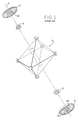
- FIG. 1 there is shown an isometric exploded view of a conventional three-axis ring laser gyroscope assembly 2 aligned along an axis 4.
- Two dither spring suspension mechanisms 6 and 8 are shown to be disposed on either side of RLG assembly 2 along axis 4. These suspension mechanisms 6 and 8 fit over hubs 10 and 12, respectively, which in turn are fastened to corresponding faces of assembly 2.
- Each of mechanisms 6 and 8 has a central annular opening 6A and 8A to facilitate attachment to hubs 10 and 12, respectively.
- each leaf 12 has fixedly coupled thereto a piezoelectric transducer element (P1 to P10), shown in Fig. 2.
- P1 to P10 the piezoelectric transducer element
- the remainder of the transducer elements - by movement in reaction to torque command signals - are used to excite spring mechanism 8 for dithering gyro block 2, in order to prevent lock-in of the RLG.
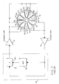
- mechanism 8 is shown to have ten leaves 8a to 8j. It should be noted that although ten leaves are shown for this embodiment, a different number of leaves, greater or less than ten, may also be utilized in a spring suspension mechanism.
- transducer elements P1 to P8 are connected in parallel to the output of a torquer amplifier 14 while transducer elements P9 and P10 are connected in parallel to an input of a pickoff amplifier 16.
- the output of pickoff amplifier 16 is fed to a conventional positive feedback ⁇ network 18 having an AGC circuit 18a and a multiplier circuit 18b, the output of which is fed to the input of torquer amplifier 14.
- the output from pickoff amplifier 16 is multiplied with some constant, i.e.
- piezoelectric elements P9 and P10 are fixedly coupled to leaves 8i and 8j, respectively.
- piezoelectric transducer elements P1 to P8 would, in response to the output voltage from torquer amplifier 14, deform, thereby vibrating spring suspension mechanism 8, which in turn dithers the gyro block of the ring laser gyroscope assembly.
- piezoelectric elements such as P9 and P10 would, in response to the sensed motion of the gyro block (by means of mechanically coupled feedback vibration to the spring suspension mechanism), convert the motion to an electrical signal, which is sent to the input of pickoff amplifier 16.
- the piezoelectric elements In view of the fact that only two of the piezoelectric elements are used for detecting the motion of the gyro block, in the event that one of the piezoelectric elements fails, 50% of the sensed signal would be lost. Therefore, absent some additional fault - detection means, improper operation would result.
- An even more ominous scenario entails if only one of the piezoelectric elements is used as the sensing, or pickoff, element. In which case even though the RLG would most likely continue to function, there is no means to ameliorate the effects of the lock-in.
- Fig. 3 illustrates a first embodiment of the present invention wherein the electromechanical system consisting of the piezoelectric elements and the suspension mechanism has been replaced by an electrical equivalent circuit, encircled by dotted box 20.
- the electromechanical system consisting of the piezoelectric elements and the suspension mechanism has been replaced by an electrical equivalent circuit, encircled by dotted box 20.
- like elements are labeled the same.
- a spring suspension mechanism or more precisely the piezoelectric elements coupled to the leaves therein, when fed a voltage such as V D from torquer amplifier 14, will produce a current i1, which is a combination of three different components: a capacitor current Cx1, an effective resistance current KQ and a back current K p ⁇ d , which is generated as a result of the deformation of the piezoelectric elements.
- a quadrature current results from Cx1, an in-phase resistance component results from KQ and an in-phase current results from K p ⁇ d .
- the present invention embodiment of Fig. 3 further includes a current transformer 22 having a first primary winding 28 connected between the output of amplifier 14 and line 24, and a second primary winding 30 also connected to the output of amplifier 14 but between it and capacitor Cx2, the other side of which is grounded.
- a simple secondary winding 34 is connected between pickoff amplifier 16 and ground.
- multiplier circuit 18b and AGC circuit 18a are considered as a part of positive feedback ⁇ network 18.
- the components of box 20 may be represented as capacitor Cx1, resistor KQ and current source K p ⁇ d . It should be appreciated that resistor KQ is not a real resistor but, rather, represents the dissipative element in the system to account for the real power being required due to the finite Q (quality factor of the resonance) of the suspension mechanism.
- transformer 22 may be a conventional audio transformer having two primary windings and a single secondary winding.
- Torquer amplifier 14 may be a high voltage amplifier or a moderately high voltage amplifier while pickoff amplifier 16 is a conventional type amplifier.
- the Fig. 3 circuit operates as follows. As shown, an output voltage V D from torquer amplifier 14 is fed to box 20, i.e. the electrical model for the piezoelectric elements and a spring suspension system. It should be noted that for this embodiment, as was discussed earlier, all of the piezoelectric elements are connected in parallel.
- the elements Cx1, KQ and K p ⁇ d together represent the electrical equivalent circuit of the piezoelectric elements, parallel-connected, as coupled to the dither suspension system.
- Cx1 is the bulk, static capacitance of the elements, and KQ represents the value of the resistance.
- K is a conversion/scaling factor which converts the mechanical loss mechanisms to a single electrical loss mechanism, namely, the value of the resistor.
- K p ⁇ d is a current generator representing the sum of the currents produced by the piezoelectric elements in response to an angular rate ⁇ d , , the time derivative of the angular displacement of the piezo-elements.
- the Fig. 3 embodiment establishes a quadrature current by means of capacitor Cx2, which is picked up by transformer 22, resulting in current i2 - i1 being fed to pickoff amplifier 16.
- the component of the current through capacitor Cx1 along line 24 equals the current through capacitor Cx2 along line 26, with the value of capacitor Cx2 being trimmed to be equal to that of capacitor Cx1.
- the current that is left from the subtraction of current i1 from i2 is the back current created by the deformation rate of the piezoelectric elements, which is proportional to the velocity of the motion of the gyro block.
- the resulting current is, as shown in Fig. 3, fed as an input to pickoff amplifier 16 which, being a current to voltage amplifier, converts the resulting current into a voltage V P , to be fed to ⁇ network 18.
- pickoff amplifier 16 which, being a current to voltage amplifier, converts the resulting current into a voltage V P , to be fed to ⁇ network 18.
- automatic gain control AGC circuit 18a and multiplier circuit 18b of ⁇ network upon receipt of voltage V P , generates a feedback signal V F to torquer amplifier 14, thereby effecting a closed electrical feedback loop for the Fig. 3 embodiment.
- Torquer 14 of course, as was discussed earlier, in receipt of signal V F , generates voltage V D , which in turn is used to oscillate the piezoelectric elements, thereby producing current i1.
- the value of capacitor Cx2 is chosen equal to that of Cx1, and the turns ratio of winding 30 to 28 is unity. In a practical implementation, however, the value of Cx2 would be chosen to be smaller than the value of Cx1. The reason is that capacitance loads imposed by Cx2 and Cx1 decrease the efficiency of amplifier 14 by requiring it to supply currents which are not productive of useful torque. By making Cx2 smaller, the total capacitive load, Cx2 + Cx1, is not that much greater than that imposed by Cx1 alone. But to effect the equivalent flux cancellation in the transformer's magnetic core, the turns ratio of winding 30 to 28 would be the reciprocal of the capacitance ratio Cx2/Cx1.
- a second embodiment of the present invention which utilizes current sensing resistors in place of transformer 22 is shown in Fig. 4.
- current sensing resistors R and R T are inserted respectively between junction 40 and capacitor C and between junction 40 and junction 44.
- the Fig. 4 embodiment shows, as before, a torquer amplifier 14 providing a voltage V D toward junction 40.
- the Fig. 4 embodiment uses a buck out capacitor C along line 48.
- current sensing resistor R and buck out capacitor C are series connected.
- sensing resistor R current I flowing through line 48 to ground is converted to a voltage drop across R.
- current I T due to sensing resistor R T , is converted to a voltage drop across R T .
- the velocity of the suspension mechanism is proportional to the difference in voltages V T and V.
- the Fig. 4 embodiment further shows a differential amplifier 50 having as its inputs voltages V and V T .
- the function of a differential amplifier is to provide as an output the difference between the voltages at its inputs. Accordingly, differential amplifier 50, in receipt of voltages V and V T , generates a difference voltage, which corresponds to the motion of the gyro block, to feedback network 18, which, upon receipt of the difference signal, provides a signal to torquer amplifier 14 to generate a voltage to be fed to box 46.
- the Fig. 3 embodiment the Fig.
- the Fig. 4 embodiment also results in a closed electrical feedback loop that provides a constant dither rate. Instead of directly measuring the difference in currents, the Fig. 4 embodiment, although also utilizing the recognition that the back current I B corresponds to the velocity of motion of the gyro block, measures the difference between two voltage drops.
- the components shown therein are, like the Fig. 3 embodiment, conventional devices. And, of course, the Fig. 4 embodiment is based on the concept of cancelling voltages which have equal magnitudes due to the voltage drops across the respective sensing resistors. Putting it differently, the Fig. 4 embodiment is a transformer-less pickoff-less system.
Landscapes
- Physics & Mathematics (AREA)
- Engineering & Computer Science (AREA)
- Optics & Photonics (AREA)
- Electromagnetism (AREA)
- Power Engineering (AREA)
- General Physics & Mathematics (AREA)
- Radar, Positioning & Navigation (AREA)
- Remote Sensing (AREA)
- Gyroscopes (AREA)
- Lasers (AREA)
Applications Claiming Priority (2)
| Application Number | Priority Date | Filing Date | Title |
|---|---|---|---|
| US190195 | 1980-09-24 | ||
| US07/190,195 US4856901A (en) | 1988-05-04 | 1988-05-04 | Velocity control system using piezoelectric transducers |
Publications (1)
| Publication Number | Publication Date |
|---|---|
| EP0341055A1 true EP0341055A1 (de) | 1989-11-08 |
Family
ID=22700378
Family Applications (1)
| Application Number | Title | Priority Date | Filing Date |
|---|---|---|---|
| EP89304488A Withdrawn EP0341055A1 (de) | 1988-05-04 | 1989-05-04 | Geschwindigkeitssteuerungssystem mit piezoelektrischem Umformer |
Country Status (3)
| Country | Link |
|---|---|
| US (1) | US4856901A (de) |
| EP (1) | EP0341055A1 (de) |
| JP (1) | JPH0263178A (de) |
Cited By (1)
| Publication number | Priority date | Publication date | Assignee | Title |
|---|---|---|---|---|
| CN102109346A (zh) * | 2010-12-15 | 2011-06-29 | 陕西宝成航空仪表有限责任公司 | 激光陀螺组合偏频方法及激光陀螺惯性测量组合装置 |
Families Citing this family (4)
| Publication number | Priority date | Publication date | Assignee | Title |
|---|---|---|---|---|
| US5173745A (en) * | 1991-04-12 | 1992-12-22 | Honeywell Inc. | Cluster dither apparatus |
| US5326163A (en) * | 1991-05-10 | 1994-07-05 | Honeywell Inc. | Dither apparatus |
| US6498651B1 (en) * | 1999-02-19 | 2002-12-24 | Thomson-Csf Sextant | Device for detecting activation movement for laser gyroscope |
| US11852483B1 (en) | 2022-08-12 | 2023-12-26 | Honeywell International Inc. | Dither motor apparatus with pickoff embedded drives for ring laser gyroscope |
Citations (3)
| Publication number | Priority date | Publication date | Assignee | Title |
|---|---|---|---|---|
| GB2044984A (en) * | 1979-03-21 | 1980-10-22 | Singer Co | Feedback system for controlling lock-in in spring suspended ring laser gyroscope |
| GB2045514A (en) * | 1979-03-21 | 1980-10-29 | Singer Co | Lock-in control system for spring suspended ring laser gyroscope |
| EP0069367A2 (de) * | 1981-07-06 | 1983-01-12 | Honeywell Inc. | Antriebseinheit zur Vibration eines Ringlasers |
Family Cites Families (2)
| Publication number | Priority date | Publication date | Assignee | Title |
|---|---|---|---|---|
| US3889166A (en) * | 1974-01-15 | 1975-06-10 | Quintron Inc | Automatic frequency control for a sandwich transducer using voltage feedback |
| US4314174A (en) * | 1980-03-25 | 1982-02-02 | Litton Systems, Inc. | Piezoelectric transducer drive having temperature compensation |
-
1988
- 1988-05-04 US US07/190,195 patent/US4856901A/en not_active Expired - Lifetime
-
1989
- 1989-05-04 EP EP89304488A patent/EP0341055A1/de not_active Withdrawn
- 1989-05-06 JP JP1114005A patent/JPH0263178A/ja active Pending
Patent Citations (3)
| Publication number | Priority date | Publication date | Assignee | Title |
|---|---|---|---|---|
| GB2044984A (en) * | 1979-03-21 | 1980-10-22 | Singer Co | Feedback system for controlling lock-in in spring suspended ring laser gyroscope |
| GB2045514A (en) * | 1979-03-21 | 1980-10-29 | Singer Co | Lock-in control system for spring suspended ring laser gyroscope |
| EP0069367A2 (de) * | 1981-07-06 | 1983-01-12 | Honeywell Inc. | Antriebseinheit zur Vibration eines Ringlasers |
Cited By (2)
| Publication number | Priority date | Publication date | Assignee | Title |
|---|---|---|---|---|
| CN102109346A (zh) * | 2010-12-15 | 2011-06-29 | 陕西宝成航空仪表有限责任公司 | 激光陀螺组合偏频方法及激光陀螺惯性测量组合装置 |
| CN102109346B (zh) * | 2010-12-15 | 2013-01-23 | 陕西宝成航空仪表有限责任公司 | 激光陀螺组合偏频方法及激光陀螺惯性测量组合装置 |
Also Published As
| Publication number | Publication date |
|---|---|
| US4856901A (en) | 1989-08-15 |
| JPH0263178A (ja) | 1990-03-02 |
Similar Documents
| Publication | Publication Date | Title |
|---|---|---|
| US5703292A (en) | Sensor having an off-frequency drive scheme and a sense bias generator utilizing tuned circuits | |
| US5434467A (en) | Vibrator and detector circuit for vibrating gyro | |
| US6079272A (en) | Gyroscopes and compensation | |
| EP0385917B1 (de) | Beschleunigungsmesser mit Pulsantrieb | |
| US5558477A (en) | Vibration damping system using active negative capacitance shunt circuit with piezoelectric reaction mass actuator | |
| JP4690652B2 (ja) | マイクロ電子機械システム | |
| RU2327109C2 (ru) | Способ компенсирования поперечного смещения в кориолисове гироскопе, а также кориолисов гироскоп, который пригоден для этой цели | |
| US10365105B2 (en) | Vibratory gyroscope | |
| JP5137398B2 (ja) | 慣性センサにおける振動や衝撃により誘導される誤差を低減するための適応回路 | |
| CN104897150B (zh) | 一种提升硅微机械陀螺仪带宽全温性能的方法 | |
| US4694696A (en) | Vibration-type gyro apparatus | |
| US6075754A (en) | Single-coil force balance velocity geophone | |
| US5378974A (en) | Vibration damping system | |
| US4856901A (en) | Velocity control system using piezoelectric transducers | |
| EP0009328A1 (de) | Dämpfung mit niedriger Rauschtemperatur mechanischer Konstruktionen | |
| US4255054A (en) | Lock-in control system for spring suspended ring laser gyroscope | |
| EP0803704A2 (de) | Vibrationskreisel | |
| US4612819A (en) | Torquer for gyros | |
| RU2789307C1 (ru) | Гироскопический стабилизатор с контуром управления усилием в опорах гироблока | |
| US4005608A (en) | Electrically controlled rate integrating device | |
| JP4449383B2 (ja) | 発振回路 | |
| JPH0628698Y2 (ja) | サ−ボ型受振器 | |
| JPH11153479A (ja) | サーボ型振動検出器 | |
| GB2215053A (en) | Electro-mechanical oscillating transducer devices | |
| JPH0949736A (ja) | 振動型ジャイロスコープの駆動装置 |
Legal Events
| Date | Code | Title | Description |
|---|---|---|---|
| PUAI | Public reference made under article 153(3) epc to a published international application that has entered the european phase |
Free format text: ORIGINAL CODE: 0009012 |
|
| AK | Designated contracting states |
Kind code of ref document: A1 Designated state(s): BE CH DE FR GB IT LI NL SE |
|
| STAA | Information on the status of an ep patent application or granted ep patent |
Free format text: STATUS: THE APPLICATION IS DEEMED TO BE WITHDRAWN |
|
| 18D | Application deemed to be withdrawn |
Effective date: 19900509 |