EP0341344A2 - Meuble servant de siège - Google Patents
Meuble servant de siège Download PDFInfo
- Publication number
- EP0341344A2 EP0341344A2 EP88120948A EP88120948A EP0341344A2 EP 0341344 A2 EP0341344 A2 EP 0341344A2 EP 88120948 A EP88120948 A EP 88120948A EP 88120948 A EP88120948 A EP 88120948A EP 0341344 A2 EP0341344 A2 EP 0341344A2
- Authority
- EP
- European Patent Office
- Prior art keywords
- seat
- backrest
- spring
- seating furniture
- frame
- Prior art date
- Legal status (The legal status is an assumption and is not a legal conclusion. Google has not performed a legal analysis and makes no representation as to the accuracy of the status listed.)
- Granted
Links
Images



Classifications
-
- A—HUMAN NECESSITIES
- A47—FURNITURE; DOMESTIC ARTICLES OR APPLIANCES; COFFEE MILLS; SPICE MILLS; SUCTION CLEANERS IN GENERAL
- A47C—CHAIRS; SOFAS; BEDS
- A47C1/00—Chairs adapted for special purposes
- A47C1/02—Reclining or easy chairs
- A47C1/031—Reclining or easy chairs having coupled concurrently adjustable supporting parts
- A47C1/032—Reclining or easy chairs having coupled concurrently adjustable supporting parts the parts being movably-coupled seat and back-rest
- A47C1/03255—Reclining or easy chairs having coupled concurrently adjustable supporting parts the parts being movably-coupled seat and back-rest with a central column, e.g. rocking office chairs
-
- A—HUMAN NECESSITIES
- A47—FURNITURE; DOMESTIC ARTICLES OR APPLIANCES; COFFEE MILLS; SPICE MILLS; SUCTION CLEANERS IN GENERAL
- A47C—CHAIRS; SOFAS; BEDS
- A47C7/00—Parts, details, or accessories of chairs or stools
- A47C7/36—Supports for the head or the back
- A47C7/40—Supports for the head or the back for the back
- A47C7/44—Supports for the head or the back for the back with elastically-mounted frame
- A47C7/445—Supports for the head or the back for the back with elastically-mounted frame with bar or leaf springs
- A47C7/4454—Supports for the head or the back for the back with elastically-mounted frame with bar or leaf springs of torsion type
-
- A—HUMAN NECESSITIES
- A47—FURNITURE; DOMESTIC ARTICLES OR APPLIANCES; COFFEE MILLS; SPICE MILLS; SUCTION CLEANERS IN GENERAL
- A47C—CHAIRS; SOFAS; BEDS
- A47C1/00—Chairs adapted for special purposes
- A47C1/02—Reclining or easy chairs
- A47C1/031—Reclining or easy chairs having coupled concurrently adjustable supporting parts
- A47C1/032—Reclining or easy chairs having coupled concurrently adjustable supporting parts the parts being movably-coupled seat and back-rest
- A47C1/03261—Reclining or easy chairs having coupled concurrently adjustable supporting parts the parts being movably-coupled seat and back-rest characterised by elastic means
- A47C1/03266—Reclining or easy chairs having coupled concurrently adjustable supporting parts the parts being movably-coupled seat and back-rest characterised by elastic means with adjustable elasticity
-
- A—HUMAN NECESSITIES
- A47—FURNITURE; DOMESTIC ARTICLES OR APPLIANCES; COFFEE MILLS; SPICE MILLS; SUCTION CLEANERS IN GENERAL
- A47C—CHAIRS; SOFAS; BEDS
- A47C1/00—Chairs adapted for special purposes
- A47C1/02—Reclining or easy chairs
- A47C1/031—Reclining or easy chairs having coupled concurrently adjustable supporting parts
- A47C1/032—Reclining or easy chairs having coupled concurrently adjustable supporting parts the parts being movably-coupled seat and back-rest
- A47C1/03261—Reclining or easy chairs having coupled concurrently adjustable supporting parts the parts being movably-coupled seat and back-rest characterised by elastic means
- A47C1/03277—Reclining or easy chairs having coupled concurrently adjustable supporting parts the parts being movably-coupled seat and back-rest characterised by elastic means with bar or leaf springs
- A47C1/03279—Reclining or easy chairs having coupled concurrently adjustable supporting parts the parts being movably-coupled seat and back-rest characterised by elastic means with bar or leaf springs of torsion type
-
- A—HUMAN NECESSITIES
- A47—FURNITURE; DOMESTIC ARTICLES OR APPLIANCES; COFFEE MILLS; SPICE MILLS; SUCTION CLEANERS IN GENERAL
- A47C—CHAIRS; SOFAS; BEDS
- A47C1/00—Chairs adapted for special purposes
- A47C1/02—Reclining or easy chairs
- A47C1/031—Reclining or easy chairs having coupled concurrently adjustable supporting parts
- A47C1/032—Reclining or easy chairs having coupled concurrently adjustable supporting parts the parts being movably-coupled seat and back-rest
- A47C1/03261—Reclining or easy chairs having coupled concurrently adjustable supporting parts the parts being movably-coupled seat and back-rest characterised by elastic means
- A47C1/03283—Reclining or easy chairs having coupled concurrently adjustable supporting parts the parts being movably-coupled seat and back-rest characterised by elastic means with fluid springs
-
- A—HUMAN NECESSITIES
- A47—FURNITURE; DOMESTIC ARTICLES OR APPLIANCES; COFFEE MILLS; SPICE MILLS; SUCTION CLEANERS IN GENERAL
- A47C—CHAIRS; SOFAS; BEDS
- A47C3/00—Chairs characterised by structural features; Chairs or stools with rotatable or vertically-adjustable seats
- A47C3/02—Rocking chairs
- A47C3/021—Rocking chairs having elastic frames
- A47C3/023—Rocking chairs having elastic frames made of tubular material
-
- A—HUMAN NECESSITIES
- A47—FURNITURE; DOMESTIC ARTICLES OR APPLIANCES; COFFEE MILLS; SPICE MILLS; SUCTION CLEANERS IN GENERAL
- A47C—CHAIRS; SOFAS; BEDS
- A47C3/00—Chairs characterised by structural features; Chairs or stools with rotatable or vertically-adjustable seats
- A47C3/20—Chairs or stools with vertically-adjustable seats
- A47C3/30—Chairs or stools with vertically-adjustable seats with vertically-acting fluid cylinder
-
- A—HUMAN NECESSITIES
- A47—FURNITURE; DOMESTIC ARTICLES OR APPLIANCES; COFFEE MILLS; SPICE MILLS; SUCTION CLEANERS IN GENERAL
- A47C—CHAIRS; SOFAS; BEDS
- A47C7/00—Parts, details, or accessories of chairs or stools
- A47C7/02—Seat parts
- A47C7/024—Seat parts with double seats
Definitions
- the invention relates to seating furniture according to the preamble of patent claim 1.
- a piece of seating furniture which has a base frame with a fixed base frame block, a seat support and a backrest support.
- the seat support is pivotably articulated on the foot frame block about an axis running horizontally and transversely to the direction of view of a person sitting on the seating furniture, while the backrest support is articulated with the foot frame block and the seat support about second and third axes running parallel to the aforementioned first axis connected is.
- the devices for synchronously coupled pivoting of the seat support and backrest support consist of the various articulated connections between the base frame, seat support and backrest support and are otherwise designed in such a way that the pivoting of the seat support and backrest support relative to the foot support block takes place in a common direction , however, the backrest support passes through a larger swivel angle than the seat support.
- the Swiveling from the working position downwards / backwards into the rest position by the body weight on the other hand the swiveling upwards / forwards from the rest position by means of an energy store, e.g. B. in the form of a gas spring, which is located below the seat support and is supported between the base block and backrest support.
- the first articulation axis of the seat support on the base frame block, the second articulation axis of the backrest support on the base frame block and the third articulation axis of the backrest support on the seat support lie approximately in a straight line or at least in the lateral areas of a middle straight line that the circular arcs of the swivel radii of the seat support and backrest support differ only slightly from one another on the third articulation axis, the first articulation of the front seat support area on the base frame block without play, the third articulation of the rear seat support end on the backrest support being designed with play.
- the seat support and backrest support are relatively complicated and have a large number of individual components, for their assembly a correspondingly large number of screw connections, screw bolts, rivet connections and the like. Like. More is required.
- the present invention has for its object to provide an improved seating with the features of the preamble of claim 1, which compared to the prior art is constructed much simpler and thus less expensive to manufacture, which also the practical need in its application nissen accommodates much better and in which, above all, the pivoting movements of the seat and backrest can be realized for the person sitting on the seating furniture much more physically.
- the aforementioned object is achieved according to the invention in that the seat support is rigid, ie. H. is pivotally fixed to the base frame and that in each case articulation connections are provided between the seat support and the seat on the one hand and between the seat support and the backrest on the other hand, which are formed by torsionally elastic connecting elements.
- the torsionally elastic connecting elements consist of torsion spring elements which can be subjected to both bending and torsion and which serve as energy stores.
- Such torsion spring elements can preferably be designed in the form of bow springs, which are preferably made of spring steel bars (claim 3).
- the two torsionally elastic connecting elements are impressed with spring preloads which are directed in opposite directions.
- the different spring preloads that are actually required are selected in particular in accordance with the restoring forces that are required for pivoting from the rest position into the working position of the seating furniture.
- the one torsionally elastic connecting element which is arranged between the seat support and the seat or the seat frame, has a preload which is set in such a way that corresponds to a seat orientation or seat inclination in which the front seat region is the most downward or the rear one Seating area is raised the highest.
- the second, torsionally elastic connecting element arranged between the seat support and the backrest or the backrest frame has an oppositely directed spring preload which corresponds to an orientation or inclination of the rear seat area and the backrest and thus a pivoting position, in which the rear seat area is raised the largest and the backrest is pivoted forward the most.
- At least one of the spring preloads of the two torsionally elastic connecting elements, as explained above te is changeable or adjustable.
- any pivoting position of the seat and backrest can be adjusted practically continuously, the desired pivoting position achieved in each case being lockable by actuating the gas spring.
- Claims 7 and 8 deal with preferred configurations and arrangements of the two torsionally elastic connecting elements.
- claims 9 and 10 relate to a favorable design of the seat support and its arrangement within the framework of the overall construction of the seating.
- Claims 11 and 12 relate to an advantageous arrangement and design of an adjustment mechanism, with the aid of which the desired spring preload of one of the two torsionally elastic connecting elements can be varied.
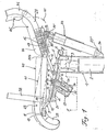
- FIG. 1 shows the side view of an office chair which has a base frame 1 which i. w. consists of a tube, a support column 2, for example designed as a gas spring, is arranged in the interior of the base frame 1 and carries at its upper end a conical pin 3 which is inserted into a corresponding sleeve 4 connected to a seat support 5.
- a base frame 1 which i. w. consists of a tube
- a support column 2 for example designed as a gas spring
- the lower end of the support column 2 of the base frame 1 is mounted on rollers (not shown here).
- the seat support 5 with the sleeve 4 and with the outer tube of the base frame 1 is fixed and i. w. pivotally connected and welded, for example, to the upper end of the base frame 1.
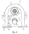
- the seat support 5 can be seen in detail from FIG. 2. It consists i. w. from a U-shaped tube 6 with two legs 8, between which a plate 7 is arranged, which is laterally firmly connected to the legs 8 and to the arcuate region of the U-tube 6.
- the plate 7, as can be seen again from FIG. 1, is firmly connected to the upper ends of the sleeve 4 and the outer tube of the base frame 1, for example by appropriate welded connections, the seat support 5 starting from the base frame 1 having an inclination , which is directed obliquely upwards towards the front end of the seat.
- the office chair i. w. a seat 43 with a seat frame 28 and a backrest 45 with a backrest frame 36, which has a lower backrest frame part 29 by which a lower region 44 of the backrest 45 is defined.
- This lower backrest area 44 practically also functions as a rear seat area, while the seat 43 practically forms the front seat area (cf. also FIG. 6).
- the seat frame 28 has two lateral, iw parallel first and second legs 28a and 28b, which are each connected via first and second swivel joints 30a and 30b to adjoining first and second legs 29a and 29b of the lower backrest frame part 29 of the backrest frame 36, whereby pivoting movements of the seat frame 28 and backrest frame 36 relative to one another are made possible .
- FIG. 1 The upper, i. w. part of the office chair consisting of the backrest 45 and armrests 38 has not been shown in FIG. 1 for reasons of space. In this regard, reference is made to FIG. 6.
- the two armrests 38 each extending from the seat frame 28 to the backrest frame 36 are provided with flexible or flexible kinks in order to be able to participate in the relative pivoting movements of the seat frame 28 and the backrest frame 38, the armrests 38 with their respective ends via correspondingly arranged swivel joints 39 are connected to both the seat frame 28 and the backrest frame 36.
- Such swivel joints 39 are shown schematically in FIGS. 1 and 6, for example, which are the articulated connections of the armrests 38 with the two first and second legs 28a and 28b of the seat frame 28 and with the two first and second legs 29a and 29b of the lower backrest frame part 29 is.
- the seat support 5 is connected to the legs 28a and 28b of the seat frame 28 via a first bow spring 9. Furthermore, the seat support 5 is via a second bow spring 15 connected to the legs 29a and 29b of the lower backrest frame part 29 of the backrest frame 36.
- first and second bow springs 9 and 15 each produce torsionally flexible articulated connections between the seat support 5 and the seat frame 28 (and thus the seat 43) on the one hand and between the seat support 5 and the lower backrest frame part 29 (and thus also the backrest 45) on the other hand , wherein these two bow springs 9 and 15, which are preferably made of spring steel and have opposite spring preloads, each represent torsion spring elements which are subjected to both bending and torsion when the seat 43 and backrest 45 are pivoted with the lower backrest region in a synchronously coupled manner, as already explained in more detail at the beginning.
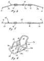
- the first bow spring 9 has a free end 10 on each side, as shown in particular in FIG. 3, and these free ends of the bow spring 9 are used to make the connections to the seat frame 28.
- the free ends 10 of the Bow spring 9 each bent parallel to the two legs 28a and 28b of the seat frame 28, while on these legs 28a and 28b each have a holding element 11, for. B. in the form of a receptacle, which is used to attach a free end 10 of the bow spring 9.
- these free ends 10 of the first bow spring 9 each extend from sections 9a and 9b which are bent at right angles to the ends of the seat support 5 pointing towards the front end of the seat.
- the bow spring 9 continues in a curved middle part 13 pointing towards the rear seat support region, which is, for example, horseshoe-shaped and movable relative to the seat support 5, the rearmost section of the curved middle part 13 being mounted in a sleeve 14 .
- the plate 7 of the seat support 5 has approximately in its central region an opening 14 ', which is arranged exactly at the level of the rear portion or rear end of the curved central part 13 and an adjustment mechanism to be explained below for adjusting the bias of the first bow spring 9 is.
- the second bow spring 15 with a bias towards the bias of the first bow spring 9 is designed in such a way that it has two free ends 16, which run parallel to the two legs 29a and 29b of the lower backrest frame part 29 and which are used to make the connections with serve the lower backrest frame part 29 and thus simultaneously with the backrest frame 36.
- the two first and second legs 29a and 29b of the lower backrest frame part 29 are connected to one another by an intermediate frame part 31, which carries in its center a sleeve-shaped fastening element 32, which supports an upper end 33 'A gas spring 33 is used, as can be seen in particular from FIGS. 1 and 7.
- this gas spring 33 which can be actuated with the aid of an associated operating lever 35, is supported with its lower end 33 ⁇ on an arm 34 of the base frame 1 directed towards the rear.
- the gas spring 33 serves to lock the respectively desired pivoting position of the seat 43 and backrest 45 in the pivoting area between the working position and the rest position of the seating furniture.
- the gas spring 33 as shown in Fig. 7, at its upper, on the intermediate frame part 31 supported end 33 'has a valve 55, in particular in the form of an on / off valve, which with the help of a Operating lever 35 (see FIG. 1) connected lever mechanism 37 can be operated.
- lever mechanism 37 This extending between the operating lever 35 and the valve 55 lever mechanism 37 is partly arranged on the intermediate frame part 31 and partly in a cavity 31 'of the intermediate frame part 31.
- the lever mechanism 37 in that section which directly adjoins the operating lever 35 initially consists of a lever arm 37 'pivotally mounted on the intermediate frame part 31'.
- This pivotable mounting of the lever arm 37 ' is realized in the embodiment according to FIG. 7 in that the lever arm 37' has a curvature, in the area of which a rotating sleeve 46 is attached to the lever arm 37 ', which is rotatably mounted on a journal 47.
- An actuating element 51 is connected to an end of the push rod 50 opposite the joint 49, through which either the closed position or the open position of the valve 55 of the gas spring 33 is directly achieved, the valve 55 being used for this purpose has a valve lifter 56 with which the actuating element 51 interacts.
- this actuating element 51 is essentially U-shaped and has an upper, essentially straight first finger 52 and a lower, second finger 53 provided with two bending points, these two bending points being arranged in such a way that an inclined guide section 54 of the second finger 53 of the actuating element 51 results between them.
- This inclined or oblique guide section 54 is preferably followed by a straight section of the second finger 53, which is located at a short distance from the first finger 52 of the actuating element 51.
- the second finger 53 of the actuating element 51 is in direct contact with its surface with a head 57 of the valve lifter 56 of the valve 55, in such a way that, as a result of a displacement of the push rod 50 within the cavity 31 'of the intermediate frame part 31, the second finger 53 of the actuating element 51 and in particular its guide section 54 is slipped over the head 57 of the valve tappet 56, whereby this is controlled and thus the valve 55 of the gas spring 33 is actuated.
- valve tappet 56 slides with its head 57 along the inclined or inclined surface of the guide section 54, as a result of which the valve tappet 56, which is preferably spring-loaded, is either pressed downwards depending on the relative displacement of the push rod 50 inside the intermediate frame part 31, which is a Relaxation of the gas spring 33 via the valve 55 results, or else the valve tappet 56 is allowed to return to occupy the highest position in which the valve 55 is closed.
- the operating lever 35 and thus also the lever mechanism 37 connected to it within a predetermined pivoting range 58 has a first (lower) position 58 ', in which the valve 55 is closed and thus the currently set pivoting position of the seat 43 and the backrest 45 is locked. This is the locking position of the gas spring 33 shown in FIG. 7.
- the operating lever 35 and the lever mechanism 37 connected to it have a second (upper) position 58 ⁇ located at the other end of the pivoting range, as is also indicated in FIG. 7, in which second position the valve 55 of the gas spring 33 is opened so that the seat 43 and backrest 45 of the office chair can be pivoted in the manner already explained above either by physical strength or by the energy accumulator (torsion spring elements).
- a further actuating linkage 21 is arranged essentially in the form of a lever arm, with the actuating linkage 21 being rotatably supported two bearing sleeves 22 are provided, which are welded, for example, to one of the legs 8 of the U-shaped tube 6.
- This to be operated with the help of a (not shown) handle linkage 21 is used to adjust the height of the support column 2 belonging to the base frame 1 and thus to adjust the height of the entire seating furniture, which, moreover, together with the upper, tubular part of the base frame 1 is rotatable with respect to the Support column 2 is mounted so that the seating shown here in the embodiment has the function of an office swivel chair.
- the support column 2 is preferably designed as a gas spring.
- the adjusting mechanism 23 for adjusting the pretension of the first bow spring 9 essentially consists of a housing 26 (cf. FIG. 1) which is fastened on the lower side of the plate 7 facing away from the first bow spring 9, specifically in the opening 14 'In the plate 7.
- an intermediate housing 27 is also housed with a bolt 25 mounted therein, in such a way that the intermediate housing 27 is displaceable in the axial direction relative to the bolt 25, which through the opening 14th 'Extending end of the intermediate housing 27 cooperates with the sleeve 14, in which the curved middle part 13 of the first bow spring 9 is mounted.
- this adjustment mechanism 23 has a rotary knob 24, in which the end of the bolt 25 facing away from the central part 13 of the bow spring 9 is fastened.
- a rotary actuation of the rotary knob 24 causes a relative displacement of the intermediate housing 27 relative to the bolt 25 and thus a change in the position of the curved middle part 13 of the first bow spring 9 either upwards or downwards, which is equivalent to an adjustment of the spring preload of the first bow spring 9, which is directed in the opposite direction to the spring preload of the second bow spring 15.
- the adjustment mechanism 23 is otherwise arranged in such a way that its axis is aligned obliquely to the axis of the base frame 1.
- Fig. 3 it is also indicated that the seat frame 28 is covered with a perforated plate 42, which in reality fills the entire space between the two seat frame legs 28a and 28b, a corresponding perforated sheet covering can also be provided in the region of the lower backrest frame part 29 , to the extent that a seat load also occurs in this lower backrest area 44.
- a perforated plate 42 which in reality fills the entire space between the two seat frame legs 28a and 28b
- a corresponding perforated sheet covering can also be provided in the region of the lower backrest frame part 29 , to the extent that a seat load also occurs in this lower backrest area 44.
- Such covering with perforated plates 42 has the advantage over the known shell constructions that very good active ventilation of the entire seat surface is made possible.
- the two extreme pivoting positions can be seen from FIG. 1, namely the working position 40, in which the rear region of the seat surface, ie in this case the lower region 44 of the backrest 45, is raised the greatest upwards, while the backrest 45 is pivoted forward most.
- the broken position curve 41 indicates the rest position in which lower region 44 of the backrest 45 (and thus practically the rear seat surface) is greatest pressed down and the backrest 45 is pivoted the farthest back.
- torsionally flexible articulation connections in particular in the form of torsion spring elements as energy stores, by means of which a separate articulation connection between the seat and seat support on the one hand and the backrest and seat support on the other hand is made possible, while the seat support itself is essentially pivotably immovable on the base frame the seat is attached.
- the inventive design of the seating furniture achieves both an improved pivotability of the seat and backrest into the working position, with additional seat elasticity being achieved, in particular also flexibility in the lateral seat areas, ie. H. depending on the weight shift of the person sitting on the seating furniture to the right or left.
- FIG. 8 shows a further exemplary embodiment of a piece of seating furniture in the form of a chair 100 with a cantilever frame 101.
- a seat 102 and a backrest 103 are connected in a known manner to such a cantilever frame 101, while armrests 104 are also formed on this cantilever frame 101.
- first articulated connections 105 between the cantilever frame 101 and the backrest 103 at the rear ends of the armrests 104 provided, these articulation connections 105 are placed lower with respect to the upper edges of the armrests 104.
- second articulation connections 107 are arranged between the cantilever frame 101 and the seat 102 in the region between the armrests 104 and a foot part 108 of the cantilever frame 101.
- the seat frame of the seat 102 and the lower backrest frame 112 of the backrest 103 are in this case connected to one another via pivot joints 106 so as to be pivotable.
- the second articulation connections 107 which are provided between the cantilever frame 101 and the seat 102, are now preferably arranged at upper free ends of spring bars 109, which in turn are fastened with their lower ends 110 to the cantilever frame 101 and in this case have a prestress, which corresponds to the working position of the chair 100, in which the seat 102 is displaced the farthest to the rear and the backrest 103 is pivoted the farthest to the front.
- a pivoting out of this working position into a rest position in which the seat 102 is displaced the most forward, while the backrest 103 is pivoted the most back, takes place through the body weight of a person sitting on the chair 100, thereby counteracting the spring force of the spring bars 109 the seat 102 is moved forward.
- the corresponding pivoting movements of seat 102 and backrest 103 relative to one another are made possible by the first and second articulated connections 105 and 107 on the cantilever frame 101, these first and second articulated connections preferably being designed in the form of rotary
- the upper ends of the two spring rods 109, which carry the second articulation connections 107, are oscillatably mounted in guide elements 111 attached to the cantilever frame 101 with corresponding guide slots.
- the backrest frame of the backrest 103 of the chair 100 shown in FIG. 8 is not designed so strongly with a backward bend.
Landscapes
- Health & Medical Sciences (AREA)
- Dentistry (AREA)
- General Health & Medical Sciences (AREA)
- Chairs Characterized By Structure (AREA)
- Chairs For Special Purposes, Such As Reclining Chairs (AREA)
- Chair Legs, Seat Parts, And Backrests (AREA)
Applications Claiming Priority (3)
| Application Number | Priority Date | Filing Date | Title |
|---|---|---|---|
| DE3812117 | 1988-04-12 | ||
| DE3812117 | 1988-04-12 | ||
| CA000613469A CA1316091C (fr) | 1988-04-12 | 1989-09-27 | Fauteuil de bureau |
Publications (3)
| Publication Number | Publication Date |
|---|---|
| EP0341344A2 true EP0341344A2 (fr) | 1989-11-15 |
| EP0341344A3 EP0341344A3 (en) | 1990-03-28 |
| EP0341344B1 EP0341344B1 (fr) | 1993-03-24 |
Family
ID=46489539
Family Applications (1)
| Application Number | Title | Priority Date | Filing Date |
|---|---|---|---|
| EP88120948A Expired - Lifetime EP0341344B1 (fr) | 1988-04-12 | 1988-12-15 | Meuble servant de siège |
Country Status (4)
| Country | Link |
|---|---|
| EP (1) | EP0341344B1 (fr) |
| CA (1) | CA1316091C (fr) |
| DE (1) | DE3879679D1 (fr) |
| ES (1) | ES2039580T3 (fr) |
Cited By (7)
| Publication number | Priority date | Publication date | Assignee | Title |
|---|---|---|---|---|
| EP0516341A1 (fr) * | 1991-05-21 | 1992-12-02 | Ashfield Engineering Company Wexford Limited | Mécanisme à bascule pour chaises |
| EP0876783A3 (fr) * | 1997-05-06 | 2000-03-01 | Broda Enterprises Inc. | Chaise inclinable |
| WO2012139233A1 (fr) * | 2011-04-12 | 2012-10-18 | Vitra Patente Ag | Mécanisme pour une chaise à réglage synchrone du dossier et de l'assise |
| EP3192398A1 (fr) * | 2016-01-15 | 2017-07-19 | himolla Polstermöbel GmbH | Couchette/siège |
| WO2020056531A1 (fr) | 2018-09-18 | 2020-03-26 | Andreas Krob | Chaise pivotante |
| CN116548762A (zh) * | 2018-04-12 | 2023-08-08 | 美国皮革运营有限责任公司 | 座椅和椅 |
| US20240008647A1 (en) * | 2021-02-19 | 2024-01-11 | Eb-Invent Gmbh | Seating furniture |
Family Cites Families (3)
| Publication number | Priority date | Publication date | Assignee | Title |
|---|---|---|---|---|
| US3545810A (en) * | 1968-09-23 | 1970-12-08 | Keystone Consolidated Ind Inc | Locking means for chair controls |
| IT1161498B (it) * | 1983-07-12 | 1987-03-18 | Castelli Spa | Sedia |
| DE3608718A1 (de) * | 1986-03-15 | 1987-09-17 | Drabert Soehne | Sitzmoebel |
-
1988
- 1988-12-15 ES ES198888120948T patent/ES2039580T3/es not_active Expired - Lifetime
- 1988-12-15 DE DE8888120948T patent/DE3879679D1/de not_active Expired - Fee Related
- 1988-12-15 EP EP88120948A patent/EP0341344B1/fr not_active Expired - Lifetime
-
1989
- 1989-09-27 CA CA000613469A patent/CA1316091C/fr not_active Expired - Fee Related
Cited By (10)
| Publication number | Priority date | Publication date | Assignee | Title |
|---|---|---|---|---|
| EP0516341A1 (fr) * | 1991-05-21 | 1992-12-02 | Ashfield Engineering Company Wexford Limited | Mécanisme à bascule pour chaises |
| US5423594A (en) * | 1991-05-21 | 1995-06-13 | Ashfield Engineering Company Wexford Limited | Chair tilting mechanism |
| EP0876783A3 (fr) * | 1997-05-06 | 2000-03-01 | Broda Enterprises Inc. | Chaise inclinable |
| WO2012139233A1 (fr) * | 2011-04-12 | 2012-10-18 | Vitra Patente Ag | Mécanisme pour une chaise à réglage synchrone du dossier et de l'assise |
| EP3192398A1 (fr) * | 2016-01-15 | 2017-07-19 | himolla Polstermöbel GmbH | Couchette/siège |
| CN116548762A (zh) * | 2018-04-12 | 2023-08-08 | 美国皮革运营有限责任公司 | 座椅和椅 |
| WO2020056531A1 (fr) | 2018-09-18 | 2020-03-26 | Andreas Krob | Chaise pivotante |
| CH715343A1 (de) * | 2018-09-18 | 2020-03-31 | Krob Andreas | Drehstuhl. |
| US20240008647A1 (en) * | 2021-02-19 | 2024-01-11 | Eb-Invent Gmbh | Seating furniture |
| US12588763B2 (en) * | 2021-02-19 | 2026-03-31 | Eb-Invent Gmbh | Seating furniture |
Also Published As
| Publication number | Publication date |
|---|---|
| DE3879679D1 (de) | 1993-04-29 |
| CA1316091C (fr) | 1993-04-13 |
| ES2039580T3 (es) | 1993-10-01 |
| EP0341344B1 (fr) | 1993-03-24 |
| EP0341344A3 (en) | 1990-03-28 |
Similar Documents
| Publication | Publication Date | Title |
|---|---|---|
| EP0179357B1 (fr) | Chaise | |
| DE3616475C1 (de) | Hoehenverstellbarer,mit Gasdruckfeder ausgestatteter Drehstuhl,insbesondere Buerostuhl oder -sessel | |
| EP0248418B1 (fr) | Siège fonctionnel | |
| EP0960586B1 (fr) | Chaise, notamment chaise de bureau | |
| DE60108555T2 (de) | Armlehne für einen Stuhl, Sessel oder dergleichen, und Stuhl mit solcher Armlehne | |
| DE3741472A1 (de) | Stuhl | |
| DE69600161T2 (de) | Verbesserungen für Systeme mit differentieller Formung von Rückenlehnen von Bürostühlen | |
| EP0264029B1 (fr) | Chaise | |
| EP3741258B1 (fr) | Chaise pourvue de mécanisme d'inclinaison de l'assise | |
| DE102009011387A1 (de) | Fluggastsitzvorrichtung | |
| EP3120732B1 (fr) | Mecanisme de siege de bureau | |
| DE3533324C2 (fr) | ||
| DE19945118A1 (de) | Sessel mit Aufstehhilfe | |
| EP3603597B1 (fr) | Chaise roulante électrique à fonction de redressement | |
| EP1258211B1 (fr) | Mécanisme synchronisé pour un mouvement correlé entre une siège et un dossier des chaises de bureau | |
| EP0341344B1 (fr) | Meuble servant de siège | |
| EP1209994B1 (fr) | Chaise | |
| EP0263323B1 (fr) | Meuble pour s'asseoir | |
| EP1632152A2 (fr) | Meuble d'assise | |
| DE3618705C2 (de) | Funktions-Sitzmöbel | |
| EP0233974A1 (fr) | Dispositif d'inclinaison pour sièges | |
| DE69714910T2 (de) | Verstellvorrichtung | |
| EP2172136A1 (fr) | Siège doté d'un élément d'assise et d'un élément de dossier | |
| EP3960032A1 (fr) | Chaise | |
| DE102004050853A1 (de) | Stuhl |
Legal Events
| Date | Code | Title | Description |
|---|---|---|---|
| PUAI | Public reference made under article 153(3) epc to a published international application that has entered the european phase |
Free format text: ORIGINAL CODE: 0009012 |
|
| AK | Designated contracting states |
Kind code of ref document: A2 Designated state(s): DE ES FR GB IT |
|
| PUAL | Search report despatched |
Free format text: ORIGINAL CODE: 0009013 |
|
| AK | Designated contracting states |
Kind code of ref document: A3 Designated state(s): DE ES FR GB IT |
|
| 17P | Request for examination filed |
Effective date: 19900420 |
|
| 17Q | First examination report despatched |
Effective date: 19910805 |
|
| GRAA | (expected) grant |
Free format text: ORIGINAL CODE: 0009210 |
|
| AK | Designated contracting states |
Kind code of ref document: B1 Designated state(s): DE ES FR GB IT |
|
| REF | Corresponds to: |
Ref document number: 3879679 Country of ref document: DE Date of ref document: 19930429 |
|
| GBT | Gb: translation of ep patent filed (gb section 77(6)(a)/1977) |
Effective date: 19930426 |
|
| ITF | It: translation for a ep patent filed | ||
| ET | Fr: translation filed | ||
| REG | Reference to a national code |
Ref country code: ES Ref legal event code: FG2A Ref document number: 2039580 Country of ref document: ES Kind code of ref document: T3 |
|
| PGFP | Annual fee paid to national office [announced via postgrant information from national office to epo] |
Ref country code: FR Payment date: 19931116 Year of fee payment: 6 |
|
| PGFP | Annual fee paid to national office [announced via postgrant information from national office to epo] |
Ref country code: GB Payment date: 19931125 Year of fee payment: 6 |
|
| PGFP | Annual fee paid to national office [announced via postgrant information from national office to epo] |
Ref country code: ES Payment date: 19931221 Year of fee payment: 6 |
|
| PLBE | No opposition filed within time limit |
Free format text: ORIGINAL CODE: 0009261 |
|
| STAA | Information on the status of an ep patent application or granted ep patent |
Free format text: STATUS: NO OPPOSITION FILED WITHIN TIME LIMIT |
|
| 26N | No opposition filed | ||
| PG25 | Lapsed in a contracting state [announced via postgrant information from national office to epo] |
Ref country code: GB Effective date: 19941215 |
|
| PGFP | Annual fee paid to national office [announced via postgrant information from national office to epo] |
Ref country code: DE Payment date: 19950726 Year of fee payment: 7 |
|
| GBPC | Gb: european patent ceased through non-payment of renewal fee |
Effective date: 19941215 |
|
| PG25 | Lapsed in a contracting state [announced via postgrant information from national office to epo] |
Ref country code: FR Effective date: 19950831 |
|
| REG | Reference to a national code |
Ref country code: FR Ref legal event code: ST |
|
| PG25 | Lapsed in a contracting state [announced via postgrant information from national office to epo] |
Ref country code: ES Free format text: LAPSE BECAUSE OF NON-PAYMENT OF DUE FEES Effective date: 19951216 |
|
| PG25 | Lapsed in a contracting state [announced via postgrant information from national office to epo] |
Ref country code: DE Effective date: 19960903 |
|
| REG | Reference to a national code |
Ref country code: ES Ref legal event code: FD2A Effective date: 19960113 |
|
| PG25 | Lapsed in a contracting state [announced via postgrant information from national office to epo] |
Ref country code: IT Free format text: LAPSE BECAUSE OF NON-PAYMENT OF DUE FEES;WARNING: LAPSES OF ITALIAN PATENTS WITH EFFECTIVE DATE BEFORE 2007 MAY HAVE OCCURRED AT ANY TIME BEFORE 2007. THE CORRECT EFFECTIVE DATE MAY BE DIFFERENT FROM THE ONE RECORDED. Effective date: 20051215 |