EP0341427A2 - Fibre monomode pour guider la lumière et méthode de fabrication de cette fibre - Google Patents
Fibre monomode pour guider la lumière et méthode de fabrication de cette fibre Download PDFInfo
- Publication number
- EP0341427A2 EP0341427A2 EP89106144A EP89106144A EP0341427A2 EP 0341427 A2 EP0341427 A2 EP 0341427A2 EP 89106144 A EP89106144 A EP 89106144A EP 89106144 A EP89106144 A EP 89106144A EP 0341427 A2 EP0341427 A2 EP 0341427A2
- Authority
- EP
- European Patent Office
- Prior art keywords
- refractive index
- optical fiber
- mode optical
- fiber according
- maximum
- Prior art date
- Legal status (The legal status is an assumption and is not a legal conclusion. Google has not performed a legal analysis and makes no representation as to the accuracy of the status listed.)
- Withdrawn
Links
Images


Classifications
-
- G—PHYSICS
- G02—OPTICS
- G02B—OPTICAL ELEMENTS, SYSTEMS OR APPARATUS
- G02B6/00—Light guides; Structural details of arrangements comprising light guides and other optical elements, e.g. couplings
- G02B6/02—Optical fibres with cladding with or without a coating
- G02B6/02004—Optical fibres with cladding with or without a coating characterised by the core effective area or mode field radius
- G02B6/02009—Large effective area or mode field radius, e.g. to reduce nonlinear effects in single mode fibres
-
- G—PHYSICS
- G02—OPTICS
- G02B—OPTICAL ELEMENTS, SYSTEMS OR APPARATUS
- G02B6/00—Light guides; Structural details of arrangements comprising light guides and other optical elements, e.g. couplings
- G02B6/02—Optical fibres with cladding with or without a coating
- G02B6/02214—Optical fibres with cladding with or without a coating tailored to obtain the desired dispersion, e.g. dispersion shifted, dispersion flattened
- G02B6/02219—Characterised by the wavelength dispersion properties in the silica low loss window around 1550 nm, i.e. S, C, L and U bands from 1460-1675 nm
- G02B6/02228—Dispersion flattened fibres, i.e. having a low dispersion variation over an extended wavelength range
- G02B6/02233—Dispersion flattened fibres, i.e. having a low dispersion variation over an extended wavelength range having at least two dispersion zero wavelengths
-
- G—PHYSICS
- G02—OPTICS
- G02B—OPTICAL ELEMENTS, SYSTEMS OR APPARATUS
- G02B6/00—Light guides; Structural details of arrangements comprising light guides and other optical elements, e.g. couplings
- G02B6/02—Optical fibres with cladding with or without a coating
- G02B6/036—Optical fibres with cladding with or without a coating core or cladding comprising multiple layers
- G02B6/03605—Highest refractive index not on central axis
- G02B6/03611—Highest index adjacent to central axis region, e.g. annular core, coaxial ring, centreline depression affecting waveguiding
-
- G—PHYSICS
- G02—OPTICS
- G02B—OPTICAL ELEMENTS, SYSTEMS OR APPARATUS
- G02B6/00—Light guides; Structural details of arrangements comprising light guides and other optical elements, e.g. couplings
- G02B6/02—Optical fibres with cladding with or without a coating
- G02B6/036—Optical fibres with cladding with or without a coating core or cladding comprising multiple layers
- G02B6/03616—Optical fibres characterised both by the number of different refractive index layers around the central core segment, i.e. around the innermost high index core layer, and their relative refractive index difference
- G02B6/03638—Optical fibres characterised both by the number of different refractive index layers around the central core segment, i.e. around the innermost high index core layer, and their relative refractive index difference having 3 layers only
- G02B6/03644—Optical fibres characterised both by the number of different refractive index layers around the central core segment, i.e. around the innermost high index core layer, and their relative refractive index difference having 3 layers only arranged - + -
-
- G—PHYSICS
- G02—OPTICS
- G02B—OPTICAL ELEMENTS, SYSTEMS OR APPARATUS
- G02B6/00—Light guides; Structural details of arrangements comprising light guides and other optical elements, e.g. couplings
- G02B6/02—Optical fibres with cladding with or without a coating
- G02B6/036—Optical fibres with cladding with or without a coating core or cladding comprising multiple layers
- G02B6/03616—Optical fibres characterised both by the number of different refractive index layers around the central core segment, i.e. around the innermost high index core layer, and their relative refractive index difference
- G02B6/03661—Optical fibres characterised both by the number of different refractive index layers around the central core segment, i.e. around the innermost high index core layer, and their relative refractive index difference having 4 layers only
- G02B6/03672—Optical fibres characterised both by the number of different refractive index layers around the central core segment, i.e. around the innermost high index core layer, and their relative refractive index difference having 4 layers only arranged - - + -
-
- G—PHYSICS
- G02—OPTICS
- G02B—OPTICAL ELEMENTS, SYSTEMS OR APPARATUS
- G02B6/00—Light guides; Structural details of arrangements comprising light guides and other optical elements, e.g. couplings
- G02B6/02—Optical fibres with cladding with or without a coating
- G02B6/036—Optical fibres with cladding with or without a coating core or cladding comprising multiple layers
- G02B6/03616—Optical fibres characterised both by the number of different refractive index layers around the central core segment, i.e. around the innermost high index core layer, and their relative refractive index difference
- G02B6/03688—Optical fibres characterised both by the number of different refractive index layers around the central core segment, i.e. around the innermost high index core layer, and their relative refractive index difference having 5 or more layers
Definitions
- the invention relates to a single-mode optical fiber with a refractive index profile n (r), where n is the refractive index of the fiber material at a distance r from the axis of the fiber, the refractive index profile by doping a matrix material, of which the fiber consists predominantly, with at least one doping material is set to form a number of layers with different refractive index.
- n is the refractive index of the fiber material at a distance r from the axis of the fiber
- the refractive index profile by doping a matrix material, of which the fiber consists predominantly, with at least one doping material is set to form a number of layers with different refractive index.
- the invention also relates to a method for its production.
- a monomode fiber with a refractive index profile is known, which is designed such that the fiber particularly fulfills three conditions with regard to chromatic dispersion: these are zeros at two preselected wavelengths and a predetermined maximum value.
- the refractive index profile is made up of three layers and shows a W-shaped course. It is not optimized with regard to the amount of doping material.
- the object of the invention is to provide a single-mode optical fiber which manages with as little doping material as possible for given properties.
- the object of the invention is also to provide a method for producing such an optical fiber.
- the fulfillment of the condition according to the invention means a minimization of the amount of the doping material and thus a corresponding reduction in the manufacturing outlay, since with the usual concentrations of doping material the resulting difference in refractive index from the undoped material is essentially proportional to the concentration of the doping material. In the case of conventional doping materials, this also applies at least approximately when there are several different doping materials, in particular a doping material which increases the refractive index and lowers the refractive index. Under these circumstances, the fulfillment of the condition according to the invention corresponds particularly well to minimizing the amount of the doping material if the effects of the refractive index changing effects of the two doping materials are essentially the same.
- the fiber is built up by changing the refractive index layer by layer.
- the requirements according to the invention can also be met with a larger number of desired properties without unnecessarily large jumps in refractive index and without an excessive deviation from the refractive index of the matrix material in that the number of layers is large compared to the number of desired properties.
- This is possible, for example, in the known plasma production processes, in which the number of possible layers and thus the number of degrees of freedom available for the design of the fiber according to the invention is approximately 1,000 (PCVD process) or even 1,000,000 (PICVD- Procedure) has risen.
- PCVD process PCVD process
- PICVD- Procedure 1,000,000
- the number of layers included in the calculation will not be too large. In general, it is sufficient if more than 100 layers are selected during the production, preferably about 300 to 500 layers.
- the fiber according to the invention is a multilayer fiber that has a characteristic sequence of almost triangular increases and decreases in the refractive index level with flat zones in between along the radius, whereby known coarse structures, namely a first, strongly pronounced minimum refractive index following a core with a relatively high refractive index, follow one another Find the following pronounced first maximum refractive index, a weak second minimum and a run-out area (EP-OS 0 224 282).
- there is a second maximum at the outer edge of the core which makes it possible to increase the chromatic dispersion at approximately 1,300 nm, which has an undesirably high negative value in known fibers, preferably to zero.
- there are several turning points between the first maximum and the second minimum This allows the refractive index to drop economically from the first maximum to the second minimum. This applies in particular if there is a step at the level of undoped matrix material, preferably SiO z , between the first maximum and the second minimum.
- a third maximum is provided in the run-out area, in which the refractive index is preferably at the level of undoped matrix material. This leads to an increase in the tunneling probability for the LP 11 photons from the core into the material located further out and thus to a favorable influence on the upper mode cutoff, ie an increase in the upper mode damping. This third maximum is so far out that it no longer disturbs the basic mode with regard to damping and dispersion.
- Refractive index profiles for the fibers according to the invention can be determined mathematically with little effort. A particularly simple possibility of such a mathematical determination is to be explained in more detail below.
- the condition according to the invention is formulated mathematically: one searches for a minimum of the function where the 1 desired properties define the permissible range in Rm, the space of the refractive indices n (r ; ) - n o , as secondary conditions, ie you can work with a quasi-continuous profile, e.g. a few hundred equidistant layers.
- this sum represents an approximation of the following integral: where R 2 represents the radius of the fiber.
- the associated fiber is calculated with the refractive index profile according to the invention in two steps. First, based on a slightly rounded step index profile, an element of the permissible range is sought using a method of the Newton type, i.e. a refractive index profile that gives the desired properties except for the minimization condition. Then you get to the minimum with the method of the projected gradient.
- the jacket may consist of pure quartz glass (Si0 2 ).
- This refractive index profile is like others by the vector formed from the refractive indices of the individual layers n described.
- the 1 (generally nonlinear) constraints are linearized locally
- a matrix M is also introduced, which contains the gradients of the constraints in its rows, and the requirements for the vector are thus formulated
- the chromatic dispersion is calculated by numerically differentiating the group delay, whereby the mode field and propagation constant are determined numerically, for example according to U. Foringham, D. Krause, R. Kunststoffmann, "Calculations to Determine the Effective Cutoff Wavelength of Single-Mode Fibers ", JOpt.Commun.8, 4, pp.143-147, 1987, and AWSnyder, JdLove," Optical Waveguide Theory ", London. New York: Chapman and Hall, 1983 ".
- n (r) The change in the refractive index profile A n (r) is assumed to be independent of the wavelength, but not the initial refractive index profile, which is recalculated for each wavelength from the concentration profile of the doping materials. This concentration profile is in turn recalculated for each step of the interation. So for the gradient: where n (r k ) has been designated n k .
- the damping of the LP 01 and LP 11 modes is calculated according to the work by Fotheringham et al. There is the loss per length with given here, the ratio of the field amplitude square on the fiber radius R 2 weighted by the radius calculated here using the WKB method (cf., for example, H.-G.Unger, "Optical Communication Technology", Part I, Heidelberg (1984) 92) to that at the effective core radius R 1 from the numerical field calculation. With R o the inner caustic is called.
- k r, inf stands for the radial component of the wave number in the medium surrounding the fiber.
- the damping calculations serve to determine the basic mode damping (see above c)) and to determine the upper mode damping (upper mode cutoff, see above b)).
- the process is terminated when the L z norm of the projected gradient has become much smaller than that of the non-projected gradient (ie smaller than a corresponding arbitrary limit, approximately 0.1).
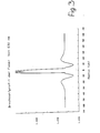
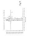
- the curve shown in FIG. 1 relates to the profile from FIG. 5. It should be noted that the refractive indices were varied in 1/10 ⁇ m intervals from zero radius to 35 ⁇ m radius.
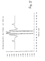
- the profile has a characteristic sequence of almost triangular increases and decreases in the refractive index level with flat zones in between, with known coarse structures, namely a Find the core 1 of relatively high refractive index following the first, highly pronounced refractive index minimum 2, a subsequent first pronounced refractive index maximum 4, a weak second minimum 5 and a run-out area 6 (EP-OS 0 224 282).
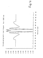
- the gradual decrease in the refractive index in FIG. 4 from the first refractive index maximum 4 to the second refractive index minimum 5 can be made more economical if it is carried out in a step-wise manner and keeps a step at the level of the matrix material. So there are several turning points, e.g. 8, 9, 10, provided there.
- the first refractive index minimum 2 is relatively low. This can cause technical difficulties. It is therefore usually advisable to introduce a minimum value of the refractive index, which should not be undercut, into the calculation process as the desired property. This can be taken into account in the calculation by introducing lower refractive index barriers according to the type of "penalty" functions in the above-mentioned standard.
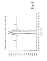
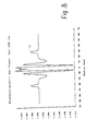
- the result of the calculation is then a natural refractive index profile which has a third refractive index maximum 11 in the outlet area 6.
- Such a refractive index profile is shown in FIG. 8.
- the third maximum 11 causes an increase in the tunneling probability for the LP11 photons from the core zone into the material surrounding the fiber and thus a favorable influence on the upper mode cutoff, i.e. an increase in upper mode damping.
- the third maximum 11 is so far out that it no longer disturbs the basic mode (i.e. its damping and dispersion).
- the third maximum had also set in early in the calculation process without establishing a low refractive index value, as can be seen from FIG. 4. But it had disappeared again on the way along the projected gradient.
- the present invention was made as part of a doctoral thesis at the Johannes Gutenberg University Mainz, Department of Physics.
Landscapes
- Physics & Mathematics (AREA)
- General Physics & Mathematics (AREA)
- Optics & Photonics (AREA)
- Chemical & Material Sciences (AREA)
- Dispersion Chemistry (AREA)
- Glass Compositions (AREA)
- Manufacture, Treatment Of Glass Fibers (AREA)
- Lasers (AREA)
- Optical Fibers, Optical Fiber Cores, And Optical Fiber Bundles (AREA)
Applications Claiming Priority (2)
| Application Number | Priority Date | Filing Date | Title |
|---|---|---|---|
| DE3812140 | 1988-04-12 | ||
| DE3812140A DE3812140A1 (de) | 1988-04-12 | 1988-04-12 | Monomode-lichtleitfaser |
Publications (2)
| Publication Number | Publication Date |
|---|---|
| EP0341427A2 true EP0341427A2 (fr) | 1989-11-15 |
| EP0341427A3 EP0341427A3 (fr) | 1991-02-27 |
Family
ID=6351811
Family Applications (1)
| Application Number | Title | Priority Date | Filing Date |
|---|---|---|---|
| EP19890106144 Withdrawn EP0341427A3 (fr) | 1988-04-12 | 1989-04-07 | Fibre monomode pour guider la lumière et méthode de fabrication de cette fibre |
Country Status (4)
| Country | Link |
|---|---|
| US (1) | US5013131A (fr) |
| EP (1) | EP0341427A3 (fr) |
| JP (1) | JPH0271204A (fr) |
| DE (1) | DE3812140A1 (fr) |
Cited By (4)
| Publication number | Priority date | Publication date | Assignee | Title |
|---|---|---|---|---|
| EP0414369A3 (en) * | 1989-07-17 | 1991-03-06 | Minnesota Mining And Manufacturing Company | Single-mode, single-polarization optical fiber |
| FR2736440A1 (fr) * | 1995-07-07 | 1997-01-10 | Alcatel Submarcom | Guide optique monomode a dispersion decalee et grande surface effective de mode |
| FR2782391A1 (fr) * | 1998-08-13 | 2000-02-18 | Alsthom Cge Alcatel | Ajout d'un anneau externe au profil d'indice d'une fibre optique monomode a dispersion decalee |
| FR2782392A1 (fr) * | 1999-08-23 | 2000-02-18 | Cit Alcatel | Fibre optique monomode a dispersion decalee comprenant un anneau exterieur |
Families Citing this family (23)
| Publication number | Priority date | Publication date | Assignee | Title |
|---|---|---|---|---|
| EP0413387A1 (fr) * | 1989-08-16 | 1991-02-20 | Koninklijke Philips Electronics N.V. | Fibre optique en mode simple maintenant la polarisation |
| DE4001781C1 (fr) * | 1990-01-23 | 1991-02-21 | Schott Glaswerke, 6500 Mainz, De | |
| US5361319A (en) * | 1992-02-04 | 1994-11-01 | Corning Incorporated | Dispersion compensating devices and systems |
| FR2724234B1 (fr) | 1994-09-05 | 1997-01-03 | Alcatel Fibres Optiques | Fibre optique monomode a dispersion decalee |
| CA2157828C (fr) * | 1994-09-13 | 2003-02-11 | Youichi Akasaka | Fibre optique a correction de la dispersion pour les transmissions a multiplexage optique |
| US5553185A (en) * | 1994-12-27 | 1996-09-03 | Corning Incorporated | Controlled dispersion optical waveguide |
| US5835655A (en) * | 1995-01-26 | 1998-11-10 | Corning Incorporated | Large effective area waveguide fiber |
| US6018533A (en) * | 1995-04-21 | 2000-01-25 | Ceramoptec Industries, Inc. | Optical fiber and integrated optic lasers with enhanced output power |
| US5822488A (en) * | 1995-10-04 | 1998-10-13 | Sumitomo Electric Industries, Inc. | Single-mode optical fiber with plural core portions |
| US5715346A (en) * | 1995-12-15 | 1998-02-03 | Corning Incorporated | Large effective area single mode optical waveguide |
| JPH1033549A (ja) * | 1996-07-24 | 1998-02-10 | Shinji Kokubu | レーザプローブ |
| WO1999012064A1 (fr) * | 1997-08-28 | 1999-03-11 | Sumitomo Electric Industries, Ltd. | Fibre a dispersion decalee |
| CN1125788C (zh) * | 1998-02-03 | 2003-10-29 | 住友电气工业株式会社 | 光纤母材的制造方法 |
| KR100636332B1 (ko) | 1998-09-21 | 2006-10-19 | 피렐리 카비 에 시스테미 소시에떼 퍼 아찌오니 | 확장 파장 밴드용의 광파이버 |
| US6292612B1 (en) * | 1999-06-07 | 2001-09-18 | Lucent Technologies Inc. | Multi-mode optical fiber having improved refractive index profile and devices comprising same |
| KR20010101087A (ko) * | 1999-10-22 | 2001-11-14 | 야마모토 토요미쯔 | 광학 감쇠기 |
| EP1238298A1 (fr) * | 1999-11-22 | 2002-09-11 | Corning Incorporated | Fibre guide d'ondes a dispersion decalee a grande surface efficace |
| US7027698B2 (en) * | 2000-03-03 | 2006-04-11 | Pirelli Cavi E Sistemi S.P.A. | Optical fiber for WDM transmission |
| JP3753975B2 (ja) * | 2001-11-29 | 2006-03-08 | 株式会社フジクラ | シングルモード光ファイバの製造方法及びシングルモード光ファイバ |
| US20040159124A1 (en) * | 2003-02-14 | 2004-08-19 | Atkins Robert M. | Optical fiber manufacture |
| US7003203B2 (en) * | 2003-07-18 | 2006-02-21 | Corning Incorporated | Large effective area, low kappa, dispersion compensating optical fiber and telecommunication span including same |
| US8107784B2 (en) * | 2007-06-15 | 2012-01-31 | Ofs Fitel, Llc | Reduced bend sensitivity and catastrophic bend loss in single mode optical fibers and method of making same |
| US8369672B2 (en) * | 2010-04-27 | 2013-02-05 | Verrillon, Inc. | Single-polarization fiber |
Family Cites Families (13)
| Publication number | Priority date | Publication date | Assignee | Title |
|---|---|---|---|---|
| US4149772A (en) * | 1975-09-22 | 1979-04-17 | Northern Electric Company Limited | Optical fibre having low mode dispersion |
| US4439007A (en) * | 1981-06-09 | 1984-03-27 | Bell Telephone Laboratories, Incorporated | Low dispersion single mode fiber |
| US4435040A (en) * | 1981-09-03 | 1984-03-06 | Bell Telephone Laboratories, Incorporated | Double-clad optical fiberguide |
| US4412722A (en) * | 1981-10-26 | 1983-11-01 | Western Electric | Single mode fiber with graded index of refraction |
| US4715679A (en) * | 1981-12-07 | 1987-12-29 | Corning Glass Works | Low dispersion, low-loss single-mode optical waveguide |
| CA1248386A (fr) * | 1982-03-11 | 1989-01-10 | Leonard G. Cohen | Fibres guides d'ondes optiques a quadruple enrobage |
| EP0131634B1 (fr) * | 1983-06-29 | 1988-06-01 | ANT Nachrichtentechnik GmbH | Fibre-W monomode |
| JPS6252508A (ja) * | 1985-09-02 | 1987-03-07 | Nippon Telegr & Teleph Corp <Ntt> | 光フアイバ |
| NL8502625A (nl) * | 1985-09-26 | 1987-04-16 | Philips Nv | Optisch transmissiesysteem bevattende een stralingsbron en een meervoudig beklede monomode optische transmissievezel met een negatieve stap in het brekingsindexprofiel. |
| US4852968A (en) * | 1986-08-08 | 1989-08-01 | American Telephone And Telegraph Company, At&T Bell Laboratories | Optical fiber comprising a refractive index trench |
| US4770492A (en) * | 1986-10-28 | 1988-09-13 | Spectran Corporation | Pressure or strain sensitive optical fiber |
| US4893896A (en) * | 1987-07-10 | 1990-01-16 | Mitsubishi Cable Industries, Ltd. | Energy transmission optical fiber |
| US4919504A (en) * | 1989-05-17 | 1990-04-24 | Bell Communications Research, Inc. | Graded-index waveguides |
-
1988
- 1988-04-12 DE DE3812140A patent/DE3812140A1/de active Granted
-
1989
- 1989-04-07 EP EP19890106144 patent/EP0341427A3/fr not_active Withdrawn
- 1989-04-12 JP JP1092805A patent/JPH0271204A/ja active Pending
- 1989-04-12 US US07/337,205 patent/US5013131A/en not_active Expired - Fee Related
Cited By (12)
| Publication number | Priority date | Publication date | Assignee | Title |
|---|---|---|---|---|
| EP0414369A3 (en) * | 1989-07-17 | 1991-03-06 | Minnesota Mining And Manufacturing Company | Single-mode, single-polarization optical fiber |
| FR2736440A1 (fr) * | 1995-07-07 | 1997-01-10 | Alcatel Submarcom | Guide optique monomode a dispersion decalee et grande surface effective de mode |
| EP0753771A3 (fr) * | 1995-07-07 | 1997-01-22 | Alcatel Submarcom | Guide optique monomode à dispersion décalée et grande surface effective de mode |
| US5675690A (en) * | 1995-07-07 | 1997-10-07 | Alcatel Submarcom | Dispersion-flattened single-mode optical waveguide with large effective mode surface area |
| FR2782391A1 (fr) * | 1998-08-13 | 2000-02-18 | Alsthom Cge Alcatel | Ajout d'un anneau externe au profil d'indice d'une fibre optique monomode a dispersion decalee |
| WO2000010043A1 (fr) * | 1998-08-13 | 2000-02-24 | Alcatel | Fibre optique monomode a dispersion decalee comprenant un anneau exterieur de l'indice de refraction |
| WO2000010042A1 (fr) * | 1998-08-13 | 2000-02-24 | Alcatel | Fibre optique monomode a dispersion decalee avec anneau exterieur de l'indice de refraction |
| EP0984308A1 (fr) * | 1998-08-13 | 2000-03-08 | Alcatel | Fibre optique monomode à dispersion décalée comprenant un anneau exterieur de l'indice de réfraction |
| EP0984309A1 (fr) * | 1998-08-13 | 2000-03-08 | Alcatel | Fibre optique monomode à dispersion décalée avec anneau exterieur d'indice de réfraction |
| US6363196B1 (en) | 1998-08-13 | 2002-03-26 | Alcatel | Single mode dispersion-shifted optical fiber with external refractive index ring |
| US6424775B1 (en) | 1998-08-13 | 2002-07-23 | Alcatel | Single mode dispersion-shifted optical fiber comprising an external refractive index ring |
| FR2782392A1 (fr) * | 1999-08-23 | 2000-02-18 | Cit Alcatel | Fibre optique monomode a dispersion decalee comprenant un anneau exterieur |
Also Published As
| Publication number | Publication date |
|---|---|
| US5013131A (en) | 1991-05-07 |
| JPH0271204A (ja) | 1990-03-09 |
| DE3812140A1 (de) | 1989-11-02 |
| EP0341427A3 (fr) | 1991-02-27 |
| DE3812140C2 (fr) | 1990-04-26 |
Similar Documents
| Publication | Publication Date | Title |
|---|---|---|
| DE3812140C2 (fr) | ||
| DE3232194C2 (fr) | ||
| DE60037365T2 (de) | Dispersionkompensierende optische Faser | |
| DE102011009242B4 (de) | Lichtwellenleiter und Halbzeug zur Herstellung eines Lichtwellenleiters mit biegeoptimierten Eigenschaften | |
| DE3312698C2 (de) | Monomode-Faser | |
| DE3307874C2 (fr) | ||
| DE3221836C2 (de) | Einzelmodenfaser | |
| EP0191202B1 (fr) | Fibres optiques dopées par le fluor et leur procédé de fabrication | |
| EP0474986A1 (fr) | Procédé pour la fabrication de fibres optiques en verre ayant une résistance à la traction augmentée | |
| DE2533144A1 (de) | Optisches faser-uebertragungsmedium | |
| EP0438653B1 (fr) | Fibre optique flexible à profil graduel pour la transmission de radiation laser à haute puissance permettant de maintenir essentiellement la structure de mode | |
| DE19505929C1 (de) | Optisches Bauteil | |
| DE69216366T2 (de) | Glasfaser für hohe Eingangsleistung und Herstellungsverfahren dafür | |
| DE69901224T2 (de) | Dispersionskompensierende Faser für ein faseroptisches Wellenlängenmultiplexübertragungssystem mit eine Dispersionsverschobene Faserstrecke | |
| DE2907650C3 (de) | Multimode-Lichtleiter | |
| DE69311168T2 (de) | Optische Faser zum Anschluss an einen Wellenleiter und Verfahren zu ihrer Herstellung | |
| EP0327702B1 (fr) | Guide d'ondes lumineuses | |
| DE19928971A1 (de) | Mehrfachmantellichtleiter, dort eingeschriebenes Langperiodenlichtleitergitter, und zugehöriges Einschreibeverfahren | |
| DE60209457T2 (de) | Optische Stufenindexfaser mit dotiertem Kern und Mantel, Vorform und Herstellungsverfahren fÜr eine solche Faser | |
| DE69900319T2 (de) | Verfahren zur Aussenabscheidung von dotiertem Quarz auf einer Vorform für optische Fasern | |
| DE69830547T2 (de) | Mehrkernfaser | |
| DE3201342C2 (de) | Optische Faser für Einmodenwelle mit einer einzigen Polarisation und Verfahren zu ihrer Herstellung | |
| EP2933238B1 (fr) | Procédé de fabrication d'une préforme de fibre optique à coeur non circulaire et manteau dopé, ayant une ouverture numérique donnée | |
| EP0413387A1 (fr) | Fibre optique en mode simple maintenant la polarisation | |
| EP0198118B1 (fr) | Fibre optique monomode en verre de silice et sa méthode de fabrication |
Legal Events
| Date | Code | Title | Description |
|---|---|---|---|
| PUAI | Public reference made under article 153(3) epc to a published international application that has entered the european phase |
Free format text: ORIGINAL CODE: 0009012 |
|
| AK | Designated contracting states |
Kind code of ref document: A2 Designated state(s): AT BE CH DE ES FR GB GR IT LI LU NL SE |
|
| RBV | Designated contracting states (corrected) |
Designated state(s): DE FR GB NL |
|
| RBV | Designated contracting states (corrected) |
Designated state(s): DE FR GB NL |
|
| PUAL | Search report despatched |
Free format text: ORIGINAL CODE: 0009013 |
|
| 17P | Request for examination filed |
Effective date: 19901219 |
|
| AK | Designated contracting states |
Kind code of ref document: A3 Designated state(s): AT BE CH DE ES FR GB GR IT LI LU NL SE |
|
| 17Q | First examination report despatched |
Effective date: 19921214 |
|
| RAP1 | Party data changed (applicant data changed or rights of an application transferred) |
Owner name: SCHOTT GLASWERKE Owner name: CARL-ZEISS-STIFTUNG TRADING AS SCHOTT GLASWERKE |
|
| STAA | Information on the status of an ep patent application or granted ep patent |
Free format text: STATUS: THE APPLICATION IS DEEMED TO BE WITHDRAWN |
|
| 18D | Application deemed to be withdrawn |
Effective date: 19940506 |