EP0341573A2 - Procédé et appareil de filtration de liquides par filtration tangentielle - Google Patents
Procédé et appareil de filtration de liquides par filtration tangentielle Download PDFInfo
- Publication number
- EP0341573A2 EP0341573A2 EP89108039A EP89108039A EP0341573A2 EP 0341573 A2 EP0341573 A2 EP 0341573A2 EP 89108039 A EP89108039 A EP 89108039A EP 89108039 A EP89108039 A EP 89108039A EP 0341573 A2 EP0341573 A2 EP 0341573A2
- Authority
- EP
- European Patent Office
- Prior art keywords
- gap
- filter
- overflow
- membrane
- liquid
- Prior art date
- Legal status (The legal status is an assumption and is not a legal conclusion. Google has not performed a legal analysis and makes no representation as to the accuracy of the status listed.)
- Withdrawn
Links
Images


Classifications
-
- B—PERFORMING OPERATIONS; TRANSPORTING
- B01—PHYSICAL OR CHEMICAL PROCESSES OR APPARATUS IN GENERAL
- B01D—SEPARATION
- B01D65/00—Accessories or auxiliary operations, in general, for separation processes or apparatus using semi-permeable membranes
- B01D65/08—Prevention of membrane fouling or of concentration polarisation
-
- B—PERFORMING OPERATIONS; TRANSPORTING
- B01—PHYSICAL OR CHEMICAL PROCESSES OR APPARATUS IN GENERAL
- B01D—SEPARATION
- B01D29/00—Filters with filtering elements stationary during filtration, e.g. pressure or suction filters, not covered by groups B01D24/00 - B01D27/00; Filtering elements therefor
- B01D29/01—Filters with filtering elements stationary during filtration, e.g. pressure or suction filters, not covered by groups B01D24/00 - B01D27/00; Filtering elements therefor with flat filtering elements
- B01D29/05—Filters with filtering elements stationary during filtration, e.g. pressure or suction filters, not covered by groups B01D24/00 - B01D27/00; Filtering elements therefor with flat filtering elements supported
- B01D29/055—Filters with filtering elements stationary during filtration, e.g. pressure or suction filters, not covered by groups B01D24/00 - B01D27/00; Filtering elements therefor with flat filtering elements supported ring shaped
-
- B—PERFORMING OPERATIONS; TRANSPORTING
- B01—PHYSICAL OR CHEMICAL PROCESSES OR APPARATUS IN GENERAL
- B01D—SEPARATION
- B01D29/00—Filters with filtering elements stationary during filtration, e.g. pressure or suction filters, not covered by groups B01D24/00 - B01D27/00; Filtering elements therefor
- B01D29/88—Filters with filtering elements stationary during filtration, e.g. pressure or suction filters, not covered by groups B01D24/00 - B01D27/00; Filtering elements therefor having feed or discharge devices
- B01D29/885—Filters with filtering elements stationary during filtration, e.g. pressure or suction filters, not covered by groups B01D24/00 - B01D27/00; Filtering elements therefor having feed or discharge devices with internal recirculation through the filtering element
-
- B—PERFORMING OPERATIONS; TRANSPORTING
- B01—PHYSICAL OR CHEMICAL PROCESSES OR APPARATUS IN GENERAL
- B01D—SEPARATION
- B01D29/00—Filters with filtering elements stationary during filtration, e.g. pressure or suction filters, not covered by groups B01D24/00 - B01D27/00; Filtering elements therefor
- B01D29/88—Filters with filtering elements stationary during filtration, e.g. pressure or suction filters, not covered by groups B01D24/00 - B01D27/00; Filtering elements therefor having feed or discharge devices
- B01D29/94—Filters with filtering elements stationary during filtration, e.g. pressure or suction filters, not covered by groups B01D24/00 - B01D27/00; Filtering elements therefor having feed or discharge devices for discharging the filter cake, e.g. chutes
- B01D29/945—Filters with filtering elements stationary during filtration, e.g. pressure or suction filters, not covered by groups B01D24/00 - B01D27/00; Filtering elements therefor having feed or discharge devices for discharging the filter cake, e.g. chutes for continuously discharging concentrated liquid
-
- B—PERFORMING OPERATIONS; TRANSPORTING
- B01—PHYSICAL OR CHEMICAL PROCESSES OR APPARATUS IN GENERAL
- B01D—SEPARATION
- B01D63/00—Apparatus in general for separation processes using semi-permeable membranes
- B01D63/08—Flat membrane modules
- B01D63/082—Flat membrane modules comprising a stack of flat membranes
- B01D63/084—Flat membrane modules comprising a stack of flat membranes at least one flow duct intersecting the membranes
-
- B—PERFORMING OPERATIONS; TRANSPORTING
- B01—PHYSICAL OR CHEMICAL PROCESSES OR APPARATUS IN GENERAL
- B01D—SEPARATION
- B01D65/00—Accessories or auxiliary operations, in general, for separation processes or apparatus using semi-permeable membranes
- B01D65/02—Membrane cleaning or sterilisation ; Membrane regeneration
-
- C—CHEMISTRY; METALLURGY
- C12—BIOCHEMISTRY; BEER; SPIRITS; WINE; VINEGAR; MICROBIOLOGY; ENZYMOLOGY; MUTATION OR GENETIC ENGINEERING
- C12M—APPARATUS FOR ENZYMOLOGY OR MICROBIOLOGY; APPARATUS FOR CULTURING MICROORGANISMS FOR PRODUCING BIOMASS, FOR GROWING CELLS OR FOR OBTAINING FERMENTATION OR METABOLIC PRODUCTS, i.e. BIOREACTORS OR FERMENTERS
- C12M29/00—Means for introduction, extraction or recirculation of materials, e.g. pumps
- C12M29/04—Filters; Permeable or porous membranes or plates, e.g. dialysis
-
- B—PERFORMING OPERATIONS; TRANSPORTING
- B01—PHYSICAL OR CHEMICAL PROCESSES OR APPARATUS IN GENERAL
- B01D—SEPARATION
- B01D2321/00—Details relating to membrane cleaning, regeneration, sterilization or to the prevention of fouling
- B01D2321/20—By influencing the flow
- B01D2321/2008—By influencing the flow statically
- B01D2321/2025—Tangential inlet
Definitions
- the invention relates to a method, a device and a filter module for breaking down or for preventing the formation of a filter cover layer in the filtration of liquids with components finely distributed therein in cross-flow operation, in which the liquid to be treated is in a narrow overflow gap between a Filter surface and a liquid-impermeable gap limiter is passed.
- Filtration using the cross-flow process is becoming increasingly important in the beverage industry.
- the liquids to be filtered are more or less heavily contaminated with finely divided components.
- the filter membranes are very quickly and strongly covered with a filter cover layer, even if an attempt is made to delay this with high flow velocities.
- the invention is therefore based on the object to enable the removal or prevention of a filter cover layer when operating a filter system using the cross-flow method with simple means in a manner which is gentle on the filter element.
- the gap limiter is brought periodically adhesive in contact with the surface of the filter cover layer building up by relative movement with respect to the filter surface and the filter cover layer of the filter surface by reactivating the overflow gap and overflow of the filter surface and Gap limiter surface is removed while flushing.
- the liquid flow of liquid to be filtered which is supplied from the outside, can be interrupted periodically in the overflow gap, or else the liquid flow is slowed down from the outside during the phase of the gap narrowing.
- the flow velocity in the gap increases according to the Venturi tube principle, and when the filter cover layer is adhesively contacted by the relatively smooth and impermeable surface of the gap limiter, the cover layer is detached from the porous filter element that both effects lead to the desired rinsing process.
- the detachment of the filter cover layer is all the more intense, the more porous the surface of the filter element facing the filter cover layer is, so that especially when using ultrafiltration membranes and microfiltration membranes, a particularly effective degradation of the filter cover layer or its prevention can be achieved.
- the gap limiter is preferably formed as a fluid-tight film membrane which can be adjusted on the side facing away from the filter element by supplying liquid into a chamber or by means of compressed gas or vacuum to form a gap approximately in the order of magnitude of 0-1000 ⁇ m.
- the degradation of the filter cover layer is further supported by turbulence.
- Filter elements can be both porous, solid filter elements, for example ceramic or glass filters, and flexible filters in the form of membranes, microporous or as relatively dense filter foils for pervaporation.
- the impermeable gap limiter can be formed by a movable wall of a housing enclosing the filter element.
- the wall can be a piston which can move in the form of a piston, but preferably a film membrane made of plastic which is tightly clamped on the edge in a surrounding housing.
- a quasi-continuous filtration operation is possible via a control device assigned to the filtration device using liquid pumps, gas pumps and valves, without the filtrate already obtained having to be used again to be fed into the retentate circuit from the filtrate side through the filter membrane.
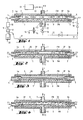
- 1 to 4 consists of the lower housing part 1 with a connection 6 for filtrate, the middle housing part 3 with diametrically opposite connections 4,5 for the liquid to be treated F1, F1 'and the upper housing part 2 with a connection 7 for pressure medium P in the form of gas or liquid or vacuum V.
- a liquid-tight, smooth film membrane FM is clamped sealingly, the rear side of which can be acted upon with fluid via the connection 7 and parallel to the actual filter surface is movable in the form of a porous membrane PM.
- This porous membrane PM is arranged between the middle housing part 3 and the lower housing part 1 and on its underside, i.e. Filtrate side supported by a flat, porous drainage layer 8.
- Both the film membrane FM and the porous membrane PM are sealed in the usual way via circumferential sealing rings or by welding relative to the housing parts 1 to 3 to form separate fluid chambers.
- a relatively narrow overflow gap SP is formed between the two membranes FM and PM, which according to the invention can be set in the order of magnitude of 0-1000 .mu.m during the filtration operation by acting on the film membrane FM.
- the filter device is part here of a sampling device for a fermenter 20.
- the connection 4 for the liquid F1 to be treated, here fermenter broth via the line 11, the check valve 10 and the pump 9 is connected to the fermenter 20.
- the connection 5 for the unconcentrated or concentrated fermenter broth F1 ' is also connected to the fermenter 20 via the line 18, the valve 19 and the line 17 in the circuit.
- Connection 6 for the fil entered F2, a 3-way valve 13, a line 12 and a valve 16 are also connected to the line 17 leading to the fermenter 20.
- a sampling point for fermenter filtrate is formed via the 3-way valve 13 via a bypass line 15 with sterile filter 14 arranged in between.
- a pressure vacuum transmitter 21 supplies line 7 to port 7 with either liquid or gaseous pressure medium P / V.
- the overflow gap SP according to FIG. 2 periodically so far narrowed by the application of the film membrane FM that it comes into contact with the surface of the filter cover layer DS adhesive surface as shown in FIG. 3.
- the adhesive forces between the relatively smooth film membrane FM and the filter cover layer DS lead to a rupture of the boundary surface of the filter cover layer DS and subsequent dissolution of the cross-sectional structure when the overflow gap SP is subsequently widened, so that the narrowing of the overflow gap SP according to the principle of a venturi channel increases Flow velocity in the overflow gap SP flowing liquid F1 dissolved filter cover layer DS according to FIG. 4 is flushed back into the fermenter circuit.
- the movement of the flexible film membrane FM which occurs during the flushing overflow supports the dissolution of the filter cover layer DS, so that, depending on the pore size of the porous membrane PM or a rigid filter medium, it is removed to remove residues in the pores.
- the draining filter support 8 is expediently kept very tight in the form of grooves or formed by a flat support fleece, so that no undulating elevations and depressions are formed on the porous membrane PM and thus the overflow gap SP is formed by two parallel boundaries.
- the porous membrane PM Due to the pulsating action of the film membrane FM in coordination with the flow of the liquid F1, F1 'and F2, the porous membrane PM can be kept free of a filter cover layer, so that the current fermenter filtrate can be removed from the removal point 15 when a sample is taken. For this purpose, only valve 16 in line 12 is closed. The removal takes place without sensitive cell cultures having to penetrate a damaging filter cover layer DS.
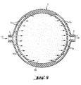
- Fig. 5 shows schematically simplified a section through the middle housing part 3 for the essentially circular filter device.
- the connections 4, 5 merge into a plurality of distribution channels 4a or collecting channels 5a.
- the movable wall forms a flow divider which divides the overflow gap into two partial gaps in the form of a film membrane FM which can be flowed over on both sides and which is movable between the walls limiting the overflow gap (porous membranes PM).
- the film membrane FM is circumferentially clamped between housing parts 1, 2, 3, 3 ', the overflow in the two sub-columns can take place in parallel or with an additional connection 4 in countercurrent.
- the film membrane FM pulsates due to its oversize or flexibility and possibly extensibility maximally between between the limiting gap walls PM.
- the film membrane FM can be made of silicone, for example, and fixed in the manner of a punched card by pins 3 ⁇ in the middle part of the housing 3.3 'at the inlet and outlet 4.5 and clamped at the other side edges.
- the overflow chamber is rectangular, it is sufficient if the film membrane FM is clamped on two opposite sides as a flow divider in the housing 1 to 3, the length of the film between the clamping points being kept somewhat larger than the distance between the clamping points, so that here too Foil can move pulsating between limit positions.
- the positions and positions of the film membrane FM between its boundary walls PM can be influenced by shut-off or throttle valves at the connections 4,5,5 ', 6,6'.
- circular individual elements are stacked on a lower end plate around a central clamping bolt 30 connected thereto and covered by a further upper end plate with fluid connections, which leads on the clamping bolt 30 and are pressed against the stack of individual elements by clamping means is, fixing elements 43 'and 43 are provided on the clamping bolt 30 and / or on the periphery of the circular individual elements, which ensure that the openings penetrating the individual elements are aligned in the stack and correspond in the correct order in the circumferential direction.
- the film membrane FM is arranged between two porous membranes PM with the interposition of spacer frames 33a, 33b and 35a, 35b, and the pressurization of the film membrane FM in the direction of one or the other porous membrane PM takes place with the aid of the liquid to be treated, so that these for better differentiation with retentate R1 and retentate R2.
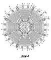
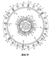
- the filtrate support plate 34 according to FIG. 8 and seen in the edge detail section according to FIGS. 9 and 10 has openings 36 distributed around the circumference on the outer edge and openings 36 ′ on the inner edge for the introduction and execution of retentate R1, corresponding openings 38, 38 ′. for the introduction and execution of retentate R2, openings 40, 40 'and connecting channels 41, 41' for the discharge of filtrate F2, the openings being completely or partially enclosed by sealing elements 42.
- the filtrate support plate 34 has a multiplicity of concentrically arranged ribs and channels as well as draining radial channels, so that a flat support surface for the porous membrane PM according to FIGS. 9 to 12 is formed.
- the filtrate support plate 34 is covered on both sides by a porous membrane PM which extends to the outer edge and to the inner edge 30 '(FIG. 8).
- the two porous membranes PM are separated by an inner (35b) and outer (35a) spacer frames from a correspondingly sized film membrane FM and the latter from a further adjacent porous membrane PM by another type of inner (33b) and outer (33a) spacer frames with connecting channels 39.39 'on the openings 38.38' for the management of retentate R2.
- the first type of spacer frame 35a, 35b also has connection channels 37.37 'for the guidance of retentate R1 in the openings 36.36'.
- the support plates 34 and spacer frames 33a, 33b, 35a, 35b are either thin metal plates or thin plastic plates.
- the sealing elements 42 including the remaining profiling, are produced in the form of grooves, connecting channels and openings in the etching process.
- the geometry of the flow guidance can be e.g. Simplify using simple radial channels and passages. Both the film membrane FM and the porous membrane PM are sealed by the groove-shaped sealing elements 42 by means of pressure and swelling in this area.
- the method described in the schematic embodiment according to FIGS. 1 to 4 for preventing or degrading a filter cover layer is carried out in that the simultaneous inflow of retentate R1 and R2 into the openings 36 and 38 is alternately periodically reduced, so that, for example, that in FIG 11 and 12 moved to the top-drawn film membrane FM with pressure increase from R2 and pressure reduction from R1 and contacted the porous membrane PM or the filter cover layer.
- the same film membrane FM moves in the direction of an overlying porous membrane with a corresponding filter support plate 34, which is no longer shown in FIGS. 11 and 12.
- the filter cover layer is detached from the first porous membrane PM and the fil flow over the overlying porous membrane PM through the retentate flow R2 and through the openings 38.38 'and connecting channels 39.39'.
- the fluid introduced between two film membranes FM for a pulsating movement of the two film membranes can also be a heat exchange medium in order to be able to temper the liquids to be filtered in accordance with the requirements.
- the method described above has the advantage that the top layer or the filter cake can be broken down as quickly as possible or the formation can be prevented directly, since it is no longer subject to aging and can therefore no longer harden. It is particularly advantageous that the aforementioned filtration unit manages with a small pumping capacity and the energy used directly on the filter membrane. comes into effect. A constantly changing stress of the filter elements due to alternating filtration operation and backwashing, as occurs in known methods for covering layer degradation, is avoided according to the invention.
Landscapes
- Chemical & Material Sciences (AREA)
- Chemical Kinetics & Catalysis (AREA)
- Wood Science & Technology (AREA)
- Health & Medical Sciences (AREA)
- Life Sciences & Earth Sciences (AREA)
- Engineering & Computer Science (AREA)
- Bioinformatics & Cheminformatics (AREA)
- Organic Chemistry (AREA)
- Zoology (AREA)
- Microbiology (AREA)
- Sustainable Development (AREA)
- Biotechnology (AREA)
- Biochemistry (AREA)
- General Engineering & Computer Science (AREA)
- General Health & Medical Sciences (AREA)
- Genetics & Genomics (AREA)
- Biomedical Technology (AREA)
- Separation Using Semi-Permeable Membranes (AREA)
- Apparatus Associated With Microorganisms And Enzymes (AREA)
Applications Claiming Priority (2)
| Application Number | Priority Date | Filing Date | Title |
|---|---|---|---|
| DE3816334 | 1988-05-13 | ||
| DE3816334 | 1988-05-13 |
Publications (2)
| Publication Number | Publication Date |
|---|---|
| EP0341573A2 true EP0341573A2 (fr) | 1989-11-15 |
| EP0341573A3 EP0341573A3 (fr) | 1990-05-09 |
Family
ID=6354293
Family Applications (1)
| Application Number | Title | Priority Date | Filing Date |
|---|---|---|---|
| EP89108039A Withdrawn EP0341573A3 (fr) | 1988-05-13 | 1989-05-03 | Procédé et appareil de filtration de liquides par filtration tangentielle |
Country Status (6)
| Country | Link |
|---|---|
| US (1) | US4990256A (fr) |
| EP (1) | EP0341573A3 (fr) |
| JP (1) | JP2885826B2 (fr) |
| DE (1) | DE3914592C2 (fr) |
| FR (1) | FR2631246B1 (fr) |
| GB (1) | GB2218352B (fr) |
Cited By (2)
| Publication number | Priority date | Publication date | Assignee | Title |
|---|---|---|---|---|
| EP1038544A1 (fr) * | 1999-03-19 | 2000-09-27 | GSF - Forschungszentrum für Umwelt und Gesundheit GmbH | Appareil de limiter l'écoulement à faible pressions différentielles |
| WO2002085493A1 (fr) * | 2001-04-23 | 2002-10-31 | N F T Nanofiltertechnik Gmbh | Dispositif de filtration |
Families Citing this family (21)
| Publication number | Priority date | Publication date | Assignee | Title |
|---|---|---|---|---|
| WO1995009987A1 (fr) * | 1993-10-04 | 1995-04-13 | Research International, Inc. | Regulateurs de debit micro-usines |
| KR970065899A (ko) * | 1997-06-30 | 1997-10-13 | 한상관 | 저장수의 배출을 조정해 해주는 장치 |
| DE19913740A1 (de) * | 1999-03-26 | 2000-10-05 | Begerow E Gmbh & Co | Filterkapsel für die Flüssigkeitsfiltration |
| DE10058939A1 (de) * | 2000-11-28 | 2002-05-29 | Reimer Goettsche | Verfahren und Vorrichtung zum Filtern |
| US7186331B2 (en) * | 2001-03-06 | 2007-03-06 | Sasol Technology (Pty) Limited | Monitoring unit for monitoring the condition of a semi-permeable membrane |
| EP1652564A1 (fr) * | 2004-10-27 | 2006-05-03 | Martin Eurlings | Dispositif de nettoyage à contre-courant |
| DE102005015421B4 (de) * | 2005-04-04 | 2012-08-30 | Wehrle Umwelt Gmbh | Verfahren zur Abtrennung von Inhaltsstoffen aus einem fließfähigen Stoffgemisch und Anlage zur Durchführung derartiger Verfahren |
| FR2888582B1 (fr) * | 2005-07-15 | 2010-08-20 | Solvay | Procede de preparation d'un polymere halogene et dispositif pour sa mise en oeuvre |
| US7648085B2 (en) | 2006-02-22 | 2010-01-19 | Rain Bird Corporation | Drip emitter |
| KR20080110862A (ko) * | 2006-03-27 | 2008-12-19 | 도레이 카부시키가이샤 | 막 엘리먼트, 막 유닛 및 다단 적층 막 유닛 |
| US9877440B2 (en) | 2012-03-26 | 2018-01-30 | Rain Bird Corporation | Elastomeric emitter and methods relating to same |
| US10631473B2 (en) | 2013-08-12 | 2020-04-28 | Rain Bird Corporation | Elastomeric emitter and methods relating to same |
| US10330559B2 (en) | 2014-09-11 | 2019-06-25 | Rain Bird Corporation | Methods and apparatus for checking emitter bonds in an irrigation drip line |
| US10375904B2 (en) | 2016-07-18 | 2019-08-13 | Rain Bird Corporation | Emitter locating system and related methods |
| US11051466B2 (en) | 2017-01-27 | 2021-07-06 | Rain Bird Corporation | Pressure compensation members, emitters, drip line and methods relating to same |
| US10626998B2 (en) | 2017-05-15 | 2020-04-21 | Rain Bird Corporation | Drip emitter with check valve |
| USD883048S1 (en) | 2017-12-12 | 2020-05-05 | Rain Bird Corporation | Emitter part |
| US11985924B2 (en) | 2018-06-11 | 2024-05-21 | Rain Bird Corporation | Emitter outlet, emitter, drip line and methods relating to same |
| RO138245A2 (ro) * | 2020-09-02 | 2024-06-28 | Exterran Water Solutions Ulc | Aparat de filtrare cu porozitate variabilă având mediu de filtrare compresibil |
| US12207599B2 (en) | 2021-10-12 | 2025-01-28 | Rain Bird Corporation | Emitter coupler and irrigation system |
| CN115212725B (zh) * | 2022-07-27 | 2023-08-18 | 东风柳州汽车有限公司 | 滤膜重复利用装置及过滤器 |
Family Cites Families (11)
| Publication number | Priority date | Publication date | Assignee | Title |
|---|---|---|---|---|
| US3387630A (en) * | 1965-04-22 | 1968-06-11 | Dow Chemical Co | Adjustable pressure reducing device |
| US3648754A (en) * | 1969-07-28 | 1972-03-14 | Hugo H Sephton | Vortex flow process and apparatus for enhancing interfacial surface and heat and mass transfer |
| JPS5818124B2 (ja) * | 1975-11-12 | 1983-04-11 | 荏原インフイルコ株式会社 | マクオセンボウシホウホウ |
| DE2653875C3 (de) * | 1976-11-26 | 1981-06-25 | Sartorius GmbH, 3400 Göttingen | Vorrichtung für die Ultrafiltration |
| US4374731A (en) * | 1980-03-06 | 1983-02-22 | Baxter Travenol Laboratories, Inc. | Method and apparatus for obtaining a desired rate of plasma collection from a membrane plasmapheresis filter |
| US4412553A (en) * | 1981-06-25 | 1983-11-01 | Baxter Travenol Laboratories, Inc. | Device to control the transmembrane pressure in a plasmapheresis system |
| NL8202703A (nl) * | 1981-10-01 | 1983-05-02 | Cobe Lab | Werkwijze en inrichting voor het afscheiden van vloeistoffiltraten, die vrij zijn van deeltjes groter dan een voorafbepaalde afmeting, uit vloeistofmengsels van de deeltjes. |
| DE3441249A1 (de) * | 1983-11-15 | 1985-05-30 | Sartorius GmbH, 3400 Göttingen | Stapelfoermiges trennelement aus geschichteten zuschnitten zur behandlung von fluiden |
| DE3411471A1 (de) * | 1984-03-28 | 1985-10-10 | Schleicher & Schuell Gmbh, 3352 Einbeck | Verfahren und vorrichtung zur kontinuierlichen druckfiltration |
| WO1986005997A1 (fr) * | 1985-04-10 | 1986-10-23 | Memtec Limited | Filtre ou concentrateur de volume variable |
| FR2586202B1 (fr) * | 1985-08-13 | 1989-11-17 | Meridional Oenologie Centre | Procedes et dispositifs de decolmatage en marche d'un filtre tangentiel |
-
1989
- 1989-05-03 DE DE3914592A patent/DE3914592C2/de not_active Expired - Fee Related
- 1989-05-03 EP EP89108039A patent/EP0341573A3/fr not_active Withdrawn
- 1989-05-11 GB GB8910863A patent/GB2218352B/en not_active Expired - Lifetime
- 1989-05-12 JP JP1117614A patent/JP2885826B2/ja not_active Expired - Lifetime
- 1989-05-12 US US07/350,932 patent/US4990256A/en not_active Expired - Fee Related
- 1989-05-12 FR FR898906273A patent/FR2631246B1/fr not_active Expired - Lifetime
Cited By (4)
| Publication number | Priority date | Publication date | Assignee | Title |
|---|---|---|---|---|
| EP1038544A1 (fr) * | 1999-03-19 | 2000-09-27 | GSF - Forschungszentrum für Umwelt und Gesundheit GmbH | Appareil de limiter l'écoulement à faible pressions différentielles |
| US6681762B1 (en) | 1999-03-19 | 2004-01-27 | Gsf-Forschungszentrum Fur Umwelt Und Gesundheit Gmbh | Method and an apparatus for providing a constant medicine dose for an inhalic application at low inhalic flow |
| WO2002085493A1 (fr) * | 2001-04-23 | 2002-10-31 | N F T Nanofiltertechnik Gmbh | Dispositif de filtration |
| US7141167B2 (en) | 2001-04-23 | 2006-11-28 | N F T Nanofiltertechnik Gmbh | Filter device |
Also Published As
| Publication number | Publication date |
|---|---|
| FR2631246A1 (fr) | 1989-11-17 |
| DE3914592A1 (de) | 1989-11-16 |
| FR2631246B1 (fr) | 1992-06-19 |
| GB2218352B (en) | 1991-12-11 |
| DE3914592C2 (de) | 1997-04-30 |
| GB8910863D0 (en) | 1989-06-28 |
| JP2885826B2 (ja) | 1999-04-26 |
| US4990256A (en) | 1991-02-05 |
| JPH0226626A (ja) | 1990-01-29 |
| EP0341573A3 (fr) | 1990-05-09 |
| GB2218352A (en) | 1989-11-15 |
Similar Documents
| Publication | Publication Date | Title |
|---|---|---|
| DE3914592C2 (de) | Verfahren und Filtermodul zur Filtration von Flüssigkeiten im Cross-Flow-Betrieb | |
| DE19827473C1 (de) | Verbesserte Crossflow-Filterkassetten | |
| DE69828597T2 (de) | Filter mit darin enthaltener filtrationskassette | |
| DE69623451T2 (de) | Filter mit darin enthaltener filtrationskassette | |
| DE69410094T2 (de) | Filter für querstromfiltration | |
| EP0131095B1 (fr) | Dispositif de filtration et de séparation de matières liquides et gazéiformes | |
| EP1144095B1 (fr) | Dispositif de concentration et/ou de purification de macromolecules en solution et procede de fabrication d'un tel dispositif | |
| DE19536560C1 (de) | Membranelement | |
| DE3750497T2 (de) | Ultrafiltrationsvorrichtung. | |
| DE2209116C3 (de) | Vorrichtung zur umgekehrten Osmose oder Ultrafiltration | |
| DE19700231A1 (de) | Vorrichtung zum Filtern und Trennen von Strömungsmedien | |
| DE3916744C2 (de) | Rohrförmiges Filterelement | |
| DE4028379A1 (de) | Filtrationsmodul und filtrationsvorrichtung zur trennung und filtration von fluiden im crossflow-verfahren, sowie verfahren zur herstellung des filtrationsmoduls | |
| EP0423609A1 (fr) | Empilement de filtres pour la réalisation d'un dispositif de filtration de fluide à courants croisés | |
| EP0875286A1 (fr) | Dispositif de filtrage avec module à membrane | |
| DE2304644A1 (de) | Vorrichtung zum zerlegen von fluessigkeiten in zwei teilmengen mittels semipermeabler membranen | |
| EP0060346A2 (fr) | Dispositif de filtration sous pression | |
| DE19857751A1 (de) | Modulfilter mit zumindest einem Zulauf für Unfiltrat und einem Ablauf für das Filtrat und mit zumindest einem Filtermodul | |
| WO2001096002A1 (fr) | Dispositif de filtration transversale de liquides | |
| DE3205229A1 (de) | Wegwerf-filter | |
| EP0120264A2 (fr) | Module de courant croisé à tubes minces | |
| DE3341262A1 (de) | Stapelfoermiges trennelement aus geschichteten zuschnitten zur behandlung von fluiden | |
| DE4012972C2 (fr) | ||
| DE3308348A1 (de) | Membranfilter | |
| DE2653875A1 (de) | Vorrichtung fuer die ultrafiltration |
Legal Events
| Date | Code | Title | Description |
|---|---|---|---|
| PUAI | Public reference made under article 153(3) epc to a published international application that has entered the european phase |
Free format text: ORIGINAL CODE: 0009012 |
|
| AK | Designated contracting states |
Kind code of ref document: A2 Designated state(s): DE ES IT NL |
|
| PUAL | Search report despatched |
Free format text: ORIGINAL CODE: 0009013 |
|
| AK | Designated contracting states |
Kind code of ref document: A3 Designated state(s): DE ES IT NL |
|
| 17P | Request for examination filed |
Effective date: 19900508 |
|
| RAP1 | Party data changed (applicant data changed or rights of an application transferred) |
Owner name: SARTORIUS AG |
|
| 17Q | First examination report despatched |
Effective date: 19910731 |
|
| RTI1 | Title (correction) | ||
| STAA | Information on the status of an ep patent application or granted ep patent |
Free format text: STATUS: THE APPLICATION IS DEEMED TO BE WITHDRAWN |
|
| 18D | Application deemed to be withdrawn |
Effective date: 19920522 |