EP0341646A2 - Procédé et dispositif de séchage d'une couche liquide appliquée sur un matériau de support en mouvement - Google Patents
Procédé et dispositif de séchage d'une couche liquide appliquée sur un matériau de support en mouvement Download PDFInfo
- Publication number
- EP0341646A2 EP0341646A2 EP89108281A EP89108281A EP0341646A2 EP 0341646 A2 EP0341646 A2 EP 0341646A2 EP 89108281 A EP89108281 A EP 89108281A EP 89108281 A EP89108281 A EP 89108281A EP 0341646 A2 EP0341646 A2 EP 0341646A2
- Authority
- EP
- European Patent Office
- Prior art keywords
- drying
- channel
- carrier material
- gas
- flow
- Prior art date
- Legal status (The legal status is an assumption and is not a legal conclusion. Google has not performed a legal analysis and makes no representation as to the accuracy of the status listed.)
- Granted
Links
Images






Classifications
-
- F—MECHANICAL ENGINEERING; LIGHTING; HEATING; WEAPONS; BLASTING
- F26—DRYING
- F26B—DRYING SOLID MATERIALS OR OBJECTS BY REMOVING LIQUID THEREFROM
- F26B21/00—Arrangements for supplying or controlling air or other gases for drying solid materials or objects
- F26B21/30—Controlling, e.g. regulating, parameters of gas supply
- F26B21/37—Velocity of flow; Quantity of flow
-
- F—MECHANICAL ENGINEERING; LIGHTING; HEATING; WEAPONS; BLASTING
- F26—DRYING
- F26B—DRYING SOLID MATERIALS OR OBJECTS BY REMOVING LIQUID THEREFROM
- F26B13/00—Machines and apparatus for drying fabrics, fibres, yarns, or other materials in long lengths, with progressive movement
- F26B13/10—Arrangements for feeding, heating or supporting materials; Controlling movement, tension or position of materials
-
- F—MECHANICAL ENGINEERING; LIGHTING; HEATING; WEAPONS; BLASTING
- F26—DRYING
- F26B—DRYING SOLID MATERIALS OR OBJECTS BY REMOVING LIQUID THEREFROM
- F26B21/00—Arrangements for supplying or controlling air or other gases for drying solid materials or objects
- F26B21/50—Ducting arrangements from the source of air or other gases to the materials or objects being dried
-
- F—MECHANICAL ENGINEERING; LIGHTING; HEATING; WEAPONS; BLASTING
- F26—DRYING
- F26B—DRYING SOLID MATERIALS OR OBJECTS BY REMOVING LIQUID THEREFROM
- F26B21/00—Arrangements for supplying or controlling air or other gases for drying solid materials or objects
- F26B21/50—Ducting arrangements from the source of air or other gases to the materials or objects being dried
- F26B21/55—Outlets for directing or distributing the air or other gases
Definitions
- the invention relates to a method and a device for drying a liquid layer which is applied to a carrier material which is moved through a drying zone and which contains evaporable solvent components and non-evaporable components.
- drying goods are, for example, metal or plastic belts, on which liquid layers are applied, which usually consist of evaporable solvent components that are removed from the liquid film during the drying process, and non-evaporable components that remain on the carrier material after drying.
- the coating gives the surfaces of the carrier materials special properties which are only present in the form after the drying process, as are desired for later use.
- An example of this is the coating of metal strips with light-sensitive layers, which are assembled into printing plates.
- the coating of metal strips or plastic films with substances in the form of a solvent-containing wet film, in the following liquid film referred to, and its subsequent drying thus represent a process that requires special systems to ensure the desired product quality of the layers.
- the process step of film drying is essential as the final process measure of the coating.
- drying liquid films on carrier materials it is customary to allow a heated gas, in particular air, to flow over the surface of the carrier materials to remove the solvent components from the film layer.
- the heated gas stream is brought into direct contact with the liquid film, which is applied in a uniform layer distribution on the carrier material, which passes through a drying device.
- the drying systems are equipped with devices which are intended to achieve a favorable or even distribution of the air flow over the liquid film. The aim is to achieve uniform drying across the entire width of the coated web.
- known drying systems have devices for minimizing disturbances in the air movements, which, in part due to turbulent flow movements, have a disadvantageous effect on the film surface and lead to mottling there.
- Difficulties in removing the dryer air from the drying room often consist in the fact that in the case of longitudinal nozzles or longitudinal slots arranged transversely to the direction of belt travel, a decrease in the nozzle outlet velocity occurs in the middle of the field due to the pressure drop in the lateral outflow and thus also affects the heat and mass transfer transversely to the direction of belt travel becomes. The consequence of this is an overdrying of the edges, which leads to undesired structuring of the dried films in many coating processes.
- pp. 290 to 294 therefore give suggestions for optimizing the design of the nozzle fields in slot nozzle dryers, which provide constant heat over the entire range of a dryer. and ensure mass transfer.
- mass transfer measurements in impingement flow from slot nozzle fields with different nozzle areas are empirically correlated in a wide range of external factors. The relationship found is used to determine optimal nozzle geometries with regard to the fan output per m2 of goods area. It is shown that a constant heat and mass transfer over the web width is achieved in that the nozzle slots have a continuously increasing slot width from the web edge to the center.
- slot nozzle fields are preferably used, in which the slots are arranged transversely to the running direction of the web.
- the observed overdrying of the edges in the slot nozzle dryers with outflow in the slot direction can be attributed to the distribution of the exit velocity along the slots.
- the outflow area should be as much as 3.5 times the nozzle exit area in order to obtain uniform drying over the width of the web.
- the dryer air is led from a vestibule via suitable inlet openings and flow deflectors into a calm space, from where part of the dryer air passes through a device arranged in close proximity to the liquid film to avoid stagnation point-like flows in the initial area of the dryer apparatus porous filter element on the web to be dried.
- the mode of operation of such drying is based on the fact that there is between the porous protective shield and the drying liquid film forms a calmed, but highly enriched, weak air flow, which is constantly renewed by exchange with the residual air flowing transversely over the porous medium and thus, due to the relatively short overall length, a predrying of the liquid film with reduced tendency to mottling is achieved .
- This type of drying is characterized by predominant diffusion of the solvent vapor / air mixture through the porous protective shield, which means that if there is almost no convective removal within the space between the belt and the protective shield, complete drying of the liquid film is only possible with very large dryer lengths or with the addition of subordinate auxiliary dryers.
- a particular disadvantage of drying devices used hitherto is that a sealing device which is compatible with the outside atmosphere must be created due to the solvent-laden air currents inside the drying room.
- a part of the required fresh air flows inwards through the finite sealing gap in the case of negative pressure conditions or a part of the solvent-laden air flows outwards in the case of overpressure conditions, whereby the flow in the sealing gap on the undried liquid film irreversible structures can be created.
- the object of the invention is to provide a method and an apparatus with which liquid layers applied to carrier materials can be dried in continuous operation in such a way that surface structures which interfere with the uniform distribution of the dried film layer and impair its desired properties, both for high and high do not occur for low-viscosity layers of liquid.
- This object is achieved by a method of the type described in the introduction in such a way that a gas flows in the longitudinal direction of the carrier material parallel to the liquid layer and is accelerated in the direction of flow within the drying zone.
- the gas flows in the same direction or in the opposite direction to the direction of travel of the carrier material and parallel to the liquid layer and is accelerated in the direction of flow within the drying zone.
- the initial speed v 1 of the gas flow is increased to a final speed v 2, which is up to 1000 times the initial speed v 1.
- the velocity distribution of the gas flow in the individual cross sections of the drying zone is set constant across the direction of travel of the carrier material.
- the gas is heated and the total gas stream is drawn off at one end of the drying zone.
- the drying zone is expediently designed in such a way that disturbances occurring in the inlet cross section and in the drying zone, such as eddies and turbulence in the gas flow, are damped and laminar by the accelerated gas flow.
- the method is used either in such a way that the drying zone is flowed through with a constant gas volume flow, the cross section of the drying zone in the running direction of the carrier material being continuously reduced, or in such a way that the gas volume flow is continuously increased in the running direction of the carrier material, with a constant cross section the drying zone or even if the cross section of the drying zone decreases.
- the turbulence of the gas flow introduced into the drying zone is immediately dampened by the gas flow locally accelerated in the flow direction and a largely laminar flow is obtained.
- the carrier material runs vertically through the drying zone and carries one side of the carrier material with a liquid layer which is dried.
- the carrier material is provided on both sides with liquid layers and both sides of the carrier material are dried by drying gas flowing in the opposite direction to the vertical direction of travel of the carrier material.
- the carrier material can also run horizontally or obliquely through the drying zone with the liquid layer applied to its underside, the drying gas flowing below the carrier material along the hanging liquid layer.
- the method is used either in such a way that the drying zone is flowed through with a constant gas volume flow, the cross section of the drying zone becoming smaller and smaller in the direction of travel of the carrier material, or in such a way that the gas volume flow is continuously increased against the direction of travel of the carrier material constant cross section of the drying zone or even with a continuously decreasing cross section of the drying zone.
- the carrier material enters the drying zone at the bottom through the dryer inlet, leaves the drying zone at the top through the dryer outlet and the total gas stream directed downwards is sucked off near the dryer inlet.
- a device for drying a liquid layer applied to a moving carrier material, which contains evaporable solvent components and non-evaporable components, with a drying channel through which the carrier material runs in the longitudinal direction runs, with a gas-permeable channel cover surface through which a drying gas stream flows into the drying channel, is characterized in that the channel cover surface is designed as a gas-permeable surface, with a permeability of the surface for the drying gas stream that can be adjusted in the longitudinal direction of the drying channel.
- the duct cover surface is inclined with respect to the horizontally running duct base surface, the duct inlet height of the drying duct being greater than the duct outlet height.
- the channel cover surface is inclined with respect to the vertical channel base surface, the channel inlet width of the drying channel being smaller than the channel outlet width.
- the channel inlet is the area in which the coating material enters the channel.
- the advantages of the invention are that the desired, trouble-free drying of low- and high-viscosity layers of liquid on carrier materials is achieved with relatively simple construction measures which effect a certain gas flow in the drying channel.
- the speed distribution is set constant in the individual drying channel cross-section, and the geometry of the drying channel is designed so that the gas disturbances occurring in the inlet cross-section and in the drying channel are dampened by the gas acceleration and that the total air flow required for drying is extracted at the end of the drying channel.
- the gas flow is laminar at the channel inlet where the liquid layer is most sensitive to blowing.
- the high flow velocity in the channel inlet area leads to a rapid removal of the solvents.
- the liquid layer dries particularly quickly and is then stable against turbulent currents that can occur at the widened channel outlet.
- the carrier material runs vertically from bottom to top, the heavy solvent vapors are removed by the opposite gas flow in the direction of gravity and not in the opposite direction.
- the air flow can be greatly accelerated and thereby the dryer section ver be shortened.
- the heat transfer in the drying zone is determined, among other things, by the gas velocity. If the gas flow is in the same direction, the belt is heated and thus it dries closer to the duct outlet, and in the opposite direction the gas is closer to the duct inlet of the drying zone.
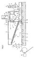
- FIG. 1 a first embodiment of a drying device 1 according to the invention is shown in a schematic sectional view.
- a carrier material strip 4 for example a metal strip made of aluminum or a foil strip, runs past a slot die 34, from which a liquid layer is applied to the carrier material strip 4, which contains evaporable solvent components and non-evaporable components.
- the carrier material strip 4 is guided around a deflection roller 35 and runs through a duct inlet 27, which has an inlet cross section A1, into a drying duct 2.
- the carrier material strip 4 runs in the drying duct 2 and in a through duct 20 adjoining the drying duct 2 on support rollers 6 which are recessed in the horizontal duct base surface 3 or in the duct bottom.
- the drying device 1 can also be designed as a dryer, in which the carrier material strip 4 is guided freely through the drying channel 2 via air-carrying nozzles and the carrier air is discharged laterally.
- a channel cover surface 7 is designed as a gas-permeable surface which is inclined with respect to the horizontally running channel base surface 3, the channel inlet height h1 of the channel inlet 27 of the drying channel 2 being greater than the channel outlet height h2 of the channel outlet 28, which has an outlet cross section A2.
- the channel cover surface 7 is inclined to the horizontal channel base surface 3, for example at an angle equal to 3 ° 9 ', the permeable channel cover surface, starting at the Channel inlet 27 extends over the entire length of the drying channel 2.
- a drying chamber 5 which is separated by an intermediate wall 10 from a gas exchange chamber 15.
- a fan 12 or a fan is arranged in the gas exchange chamber 15, the fan outlet 16 of which is directed against a heat exchanger 17 in the intermediate wall 10.
- a throttle device e.g. a throttle valve 13 is arranged, which is adjustable about a horizontal axis.
- the gas exchange chamber 15 has a gas inlet 19 which adjoins the top surface of the gas exchange chamber 15 and contains a throttle valve 14 as a throttle device.
- the throttle device can also consist of two perforated plates which can be displaced relative to one another or a lamella diaphragm device.
- the blower 12 is a double-flow circulating blower with back blades, the fresh gas stream added to the back blades from the gas inlet 19 being conveyed into the drying chamber 5.
- the flow channel 20, which connects to the drying channel 2 has a constant cross section corresponding to the channel outlet cross section A2 of the drying channel.
- the underside of the bottom surface 18 of the gas exchange chamber 15 is also the top surface of the Flow channel.
- a throttle valve 8 is arranged in an outlet 11 of the suction fan 9.
- the channel cover surface 7 consists for example of a continuous filter with constant permeability.
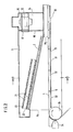
- FIG. 2 shows a schematic sectional view of a second embodiment of the drying device 1 according to the invention, which, compared to the first embodiment, has additional metering devices 21 for the gas to be added on the upper side of the channel cover surface 7.
- the gas is generally heated air.
- the drying channel 2 is similar to the drying channel of the first embodiment, with a horizontal channel base or bottom surface 31 and an inclined channel top surface 7.
- the gas or air flow in the inlet cross section A 1 of the channel inlet has an entry speed v 1 of almost zero, while the exit speed v2 can be up to 75 m / sec in the outlet cross-section A2 of the duct outlet.
- the suction fan which is identified by the reference number 9 in FIG. 1, is not shown, although it is present, as in the first exemplary embodiment.
- the metering devices 21 consist of boxes with two perforated diaphragms 22, 23, the opening cross sections of which are adjustable. These perforated diaphragms 22, 23 either lie directly one above the other or, as shown, have a distance from one another. Depending on the setting of the opening cross sections of the perforated diaphragms 22, 23 (see FIGS. 3A and 3B), there are different permeabilities of the individual boxes of the metering devices 21, so that, depending on the lengths of the boxes, different amounts of air flow through the duct cover surface 7. It is thus possible to regulate the gas or air quantity flowing into the drying duct 2 differently over the length of the drying duct 2, in addition to the different gas quantity distribution that occurs without the metering devices.
- the bottom surface 31 of the drying device has a plurality of openings 32, one of which is opposite the gas exchange chamber 15 and is subjected to the same suction pressure or negative pressure as that prevailing in the gas exchange chamber. This ensures that the carrier tape material 4, which runs through the drying channel 2 on support rollers 6, is subjected to the same negative pressure from both sides, so that a lifting of the carrier material tape 4 is prevented, as normally occurs in the direction of the gas exchange chamber 15, if only there is negative pressure .
- the remaining openings 32 which can also be arranged in the side walls, just above the bottom surface, allow the gas layers located in the immediate vicinity of the side walls to be extracted.
- the drying channel cross section is rectangular, the channel height decreasing linearly in the direction of the channel outlet cross section A2.
- the channel cover surface 7 and the metering devices 21 are embedded, for example, in the side walls 29, 30 of the drying channel 2.
- One of the openings 32 can be seen in the bottom surface 31.
- FIGS. 4A and B each show a perspective view of a drying duct 2 which has a trumpet-shaped geometry that tapers in the longitudinal direction from the duct inlet to the duct outlet.
- a drying channel can be used in the exemplary embodiments according to FIGS. 1 to 3, 9 and 10 instead of the drying channels shown there. Due to the tapering trumpet-shaped geometry of the drying channels it is ensured that the air or gas flow is accelerated in the direction of flow.
- the drying channel according to FIG. 4A has a curved top surface and curved side walls, while the drying channel according to FIG. 4B has a rectangular cross section, ie side walls oriented perpendicular to the bottom surface, but has a curved top surface.
- the acceleration of the flow in the drying channel can be achieved by two different modes of operation or by a combination of these two modes of operation.
- the first mode of operation the flow through the drying channel 2 takes place with a constant air volume flow which is present in all cross-sections of the drying channel, the cross-sections of the drying channel in the direction of the belt running from the inlet cross-section A 1 to the outlet cross-section A 2 continuously becoming smaller.
- the length-dependent reduction of the channel cross-section is carried out in such a way that disturbances introduced into the flow are attenuated and the flow thereby becomes laminar.
- the gas or air volume flow required for drying is added via suitable metering devices which are attached in or above the duct cover surface.
- the gas or air volume flow in the drying channel is continuously increased in the belt running direction or adjusted so that disturbances are damped out and the gas or air flow changes into a laminar flow.
- the gas or air volume flow required for drying into the drying chamber 5 via the blower 12 or the circulation fan with back blades with open throttle valves 13 and 14 promoted.
- the air or gas quantity flows via the metering devices and the channel cover surface 7 into the drying channel 2 and is accelerated therein to the exit velocity v2 in the outlet cross section A2.
- the blower 9 or the fan is set here so that only the gas added via the blades of the blower 12 or the circulation fan is sucked out of the drying chamber 5 and the residual gas quantity is continuously conveyed in the circuit. This ensures that almost no flow or only a very small flow occurs in the inlet cross-section A 1.
- the gas or. Air volume flow via the metering devices and the channel cover surface 7 and / or the channel outlet 28 is conveyed into the drying channel 2 and accelerated therein to the exit velocity in the channel inlet cross section.
- the inlet cross-section A 1 is designed so large for optimum operation, or the initial speed v 1 is kept so small that no initial interfering effects in the form of mottling or large-area blows occur on the liquid film to be dried .
- the coated carrier material strip 4 is guided in the immediate vicinity of the horizontal channel base surface 3 and the flow acceleration is brought about by the channel cover surface 7 which is inclined in a straight line in the direction of flow.
- the shape of the channel cross section is rectangular and the channel height decreases linearly from the channel inlet height h1 to the channel outlet height h2.
- the same effect will achieved for example with the trumpet-shaped geometries of the drying duct 2 shown in FIGS. 4A and B.
- other channel geometries are possible as long as they bring about the acceleration required in the direction of flow.
- the coated carrier material strip 4 is guided in the immediate vicinity of the vertical channel base surface 3 and the flow acceleration is brought about by the channel cover surface 7 converging in the direction of flow toward the channel base surface.
- the shape of the channel cross-section is rectangular, and the channel width decreases linearly from the channel outlet width b2 to the channel inlet width b1.
- the same effect is achieved, for example, with the trumpet-shaped geometries of the drying duct 2 shown in FIGS. 4A and B.
- other channel geometries are possible as long as they bring about the acceleration required in the direction of flow.
- the horizontal or vertical channel cover surface 7 is designed as a continuous, gas-permeable filter with a rectangular channel cross section.
- the channel cover surface 7 does not have to consist of a continuous filter, but rather can also consist of lined-up, equally thick filter mats 26 (see FIGS. 5A and 12A) with different permeability. This can also be achieved in that the filter mats have the same consistency or structure, but have different thicknesses. Another possibility is to design the filter mats with the same thickness, but with a different structure or different consistency.
- the gas flow rate and thus the flow acceleration is determined by the inclination of the duct cover surface. If the inclined duct cover surface 7 consists of a continuous filter or of filter mats, these expediently have a uniform structure or uniform consistency and thus constant permeability over the length of the drying duct 2.
- the combined use of the first and second modes of operation has advantages particularly when solvent vapors which have already been released have to be suctioned off during the coating, which is generally carried out immediately before the drying device 1 through the slot die 34.
- the accelerated flow in both the first and the second mode of operation apparently contributes in several ways to the rapid drying of the liquid layer and to the structure-free surface design of the coated carrier material strips.
- Investigations carried out show that macroscopic flow turbulences, which are generated, for example, by the addition points of the gas or air flow, are damped in drying channel 2 with the correct setting of the first or second mode of operation so that no disturbances in the drying process occur immediately after the addition points, i.e. the flow becomes laminar already in the immediate vicinity of the point of origin of the turbulence.
- this is enforced by the acceleration of the turbulent partial areas of the gas or air flow with simultaneous longitudinal alignment or longitudinal deformation of these turbulent areas.
- the accelerated gas or air flow runs near the belt parallel to the carrier material belt and is directed in the same direction or in the opposite direction to its direction of travel, so that the gas / air flow, which is getting faster and faster relative to the liquid film and its boundary layer flow in the vicinity of the liquid film, the diffusion paths of the evaporating Solvent are kept small and thus a large heat and mass transfer from the liquid layer to the drying medium is made possible at a high final velocity of the gas / air flow, but with a small drying channel length.
- the constant velocity of the flow across the width of the liquid-coated carrier material strip 4 to be dried results in very uniform drying of the liquid film transverse to the direction of web travel. This means that the velocity distribution of the gas / air flow in the individual cross sections of the drying zone or the drying channel must be kept constant across the running direction of the carrier material strip.
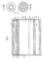
- FIG. 5A shows a schematic sectional view of a third embodiment of the drying device 1, in which the drying duct 2 has a horizontally running duct cover surface 7 which runs parallel to the duct base surface 3.
- the horizontal channel cover surface 7 consists of lined up, equally thick filter mats 26, which have different permeability to a gas or air.
- the different permeability is indicated by hatchings of different strengths of the individual filter mats 26, in such a way that the filter mat near the channel inlet is hatched more, corresponding to its lower permeability, and the hatchings of the filter mats 26 decrease in the direction of the channel outlet to indicate that the permeability of the filter mats increases in the running direction of the carrier material band 33.
- a sealing mat 36 is located in front of the channel inlet 27 of the drying channel 2.
- the channel cross sections are constant over the length of the drying channel 2. Because of the different permeability of the filter mats 26, a different amount of gas / air flows through the individual filter mat 26, which is indicated by the size of the curved arrows P1 to P5, which are assigned to the individual filter mats 26.
- the increase in the amount of gas / air supplied in the direction of the channel outlet results in an acceleration of the flow in the running direction of the carrier material band 33. This acceleration or this increase in speed of the flow towards the channel outlet is due to the increasing speed arrows v i , which are parallel to the carrier material band 33 are indicated.
- the fourth embodiment shown in FIG. 5B is the same as the third embodiment except for the top surface.
- the top surface 7 of the fourth embodiment has constant permeability over the channel length. Since the gas volume flow supplied via the top surface increases in the direction of the outlet cross section even with constant permeability of the top surface, this takes place an acceleration of the flow in the running direction of the carrier material strip 33.
- the gas / air-permeable channel cover surface 7 constructed from filter mats 26 is not horizontal, i.e. runs parallel to the channel base 3, but, like in the first and second embodiment of the drying device according to the invention, is inclined to the channel base 3.
- the channel cover surface 7 may also consist of filter mats of the same structure and consistency, but of different thicknesses, which are lined up, the thickness of the filter mats decreasing in the running direction of the carrier material band 33, i.e. in other words, the permeability of the filter mats increases in the direction of the channel outlet.
- the filter or filter mats are commercially available so-called laminar flow filters, such as those used in supply air filter systems in clean rooms.
- Such filter elements on the one hand filter dirt particles out of the gas / air flow and on the other hand ensure a very uniform laminar flow through the individual filter elements into the drying channel.
- FIG. 6 shows a fifth embodiment of the drying device according to the invention in section, in which the channel cover surface 7 is inclined with respect to the horizontal channel base surface 3.
- the channel cover surface 7 is gas / air permeable and consists of a continuous filter but can also be made of strung filter mats, as shown in Figure 5A.
- Dispensing devices 24 containing lamellae 25, which are mutually adjustable, are located above the channel cover surface 7.
- the individual lamella lies parallel to the channel cover surface 7 and is adjustable along its longitudinal axis.
- the arrangement of the slats 25 and their adjustability is roughly comparable to sun visors which are made up of slats and is indicated in Fig. 6, in which the slats 25 near the inlet cross section A 1 are shown in parallel and near the outlet cross section A 2 perpendicular to the top surface 7.
- the remaining components of the fifth embodiment are the same as the corresponding components of the first to third embodiments of the drying device, and their description will therefore not be repeated.
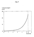
- FIGS. 7 and 8 show a velocity profile of the gas / air flow or a pressure profile, namely the static negative pressure of the flow relative to the atmospheric pressure, in each case as a function of the channel length of the drying channel.
- the course of the speed profile is very similar to the course of the pressure profile over the channel length. Up to the middle of the channel length, which in the present case is approximately 5.4 m, the speed of the flow or the vacuum increases approximately linearly with the channel length, while in the second half of the drying channel a strong exponential increase of these variables occurs.
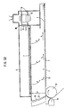
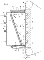
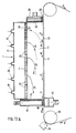
- FIG. 9 shows a sixth embodiment of the drying device 1 according to the invention in a schematic sectional view.
- the carrier material strip 4 for example a metal strip made of aluminum or a foil strip, runs past the slot die 34, from which a liquid layer is applied to the carrier material strip 4, which contains evaporable solvent components and non-evaporable components.
- the carrier material strip 4 is guided around the deflection roller 35 and runs vertically upwards through a duct inlet 27, which has a duct inlet width b1, into the drying duct 2.
- the carrier material strip 4 runs in the drying duct 2 on support rollers 6, which are recessed in the vertical duct base 3 or in the duct bottom.
- the drying device 1 can also be designed as a dryer in which the carrier material strip 4 is guided so as to float over air-carrying nozzles.
- the carrier material band can also be in contact with the channel bottom by negative pressure in the channel inlet area and then be guided through the drying channel 2 via support rollers.
- the channel cover surface 7 is designed as a gas-permeable surface which is inclined with respect to the vertically running channel base surface 3, the channel inlet width b1 of the channel inlet 27 of the drying channel 2 being smaller than the channel outlet width b2 of the channel outlet 28.
- the channel cover surface 7 extends, for example, starting at the channel inlet 27, over the entire length of the drying channel 2.
- the channel cover surface 7 consists of a continuous filter with constant permeability.
- the cross sections of the drying duct 2 are rectangular, the duct width increasing linearly upwards from the duct inlet 27 to the duct outlet width b2.
- An air space 67 of the drying device 1 is located to the side of the drying channel 2.
- Inflow channels 44, 45, 46 are arranged in the vertical side wall of the air space 67, through which drying gas, in particular heated air, flows and through the channel cover surface 7 in the direction of the arrows P in the drying channel 2 enters.
- the channel outlet 28 of the drying channel 2 is closed off by an inflow box 39 with a filter mat 48, through the drying gas in the flow direction B downwards, in the opposite direction to the running direction A of the carrier material strip 4, through the channel inlet 27 into a suction box 37 which flows the channel inlet closes at the bottom.
- the suction box 37 is equipped with a filter mat 47 and a diagonally arranged perforated baffle plate 49 which prevents eddy formation in the gas flow.
- the inflow box 39 can also be equipped with a perforated baffle plate 73.
- the baffle plate 49 can also be omitted if the filter mat 47 alone is sufficient to suppress vortex formation.
- the duct cover surface 7 can be made of impermeable material, and the blowing of a drying gas through the side wall ent falls so that the inflow channels in the vertical side wall of the drying device 1 can be omitted.
- the drying duct 2 is closed at the duct inlet 27 and at the duct outlet 28 by lamellar seals 38 or 40 or labyrinth seals as tightly as possible against the moving carrier material strip 4.
- the lamella seals 38 and 40 are attached to the vertical outer walls of the suction box 37 and the inflow box 39, which face the carrier material band 4.
- the drying gas is drawn off through the suction box 37, whereby depending on the narrowing of the channel cross section and the amount of the fed or extracted drying gas, a speed increase in the gas flow from top to bottom in the drying channel 2 arises, which suppresses turbulence.
- the carrier material strip 4 emerging from the channel outlet 28 is guided through a deflection roller 36 from the vertical direction in a certain direction for further processing.
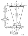
- FIG. 10 shows a schematic sectional view of a seventh embodiment of the drying device for drying the carrier material tape 4 on both sides, which, for example, carries a liquid layer on both sides and runs vertically from bottom to top through the drying device.
- the two drying channels 2 and 2 ' are symmetrical to the vertical.
- Figure 10 the components located outside the drying duct 2, which connect to the inflow box 39 and the suction box 37, are shown, while the same components connected to the right drying duct 2 'have been omitted to simplify the drawing.
- the carrier material strip 4 runs obliquely from top to bottom into a container 50 with the liquid to be applied, consisting of evaporable solvent components and non-evaporable components, and is turned around a deflection roller 51 vertically upward through the gap of squeeze rollers 52, 53 and between the suction boxes 37, 37 'Passed into the drying device.
- the carrier material strip 4 is coated on both sides with liquid, the excess of which is squeezed off in the gap between the squeezing rollers 52, 53.
- the carrier material strip 4 separates the two drying channels 2, 2 'from one another and emerges from the drying device between the two inflow boxes 39, 39'.
- the drying gas is blown over the filter mats or metal mesh or the like of the inflow boxes 39, 39 'into the drying channels 2, 2' in the flow directions B, B 'vertically downward, in the opposite direction to the running direction A of the carrier material strip 4.
- the drying channel cross sections narrow downwards, which leads to an acceleration of the drying gas flows in the direction of the channel inlets.
- the drying gas is sucked through the filter mats or metal mesh of the suction boxes 37, 37 ', which close off the channel inlets.
- the drying gas extracted by the left suction box 37 flows through a recirculation line 54, in which a throttle valve 55 is arranged, into a ventilation box 56.
- the ventilation box 56 has a fresh air supply line, in which a throttle valve 58 is mounted to regulate the quantity of fresh air supplied.
- the fresh air flows in the flow direction C into the ventilation box 56.
- an exhaust air line is attached to the ventilation box 56, in which air used in the flow direction D is discharged.
- a throttle valve 59 for controlling the amount of air discharged.
- the circulating air line leads through a heat exchanger 57, in which the air flowing in the circulating air line is heated before it enters the inflow box 39 via a throttle valve 60.
- the amount of air flowing out of the drying duct 2 'via the suction box 37' circulates in the same manner as described above, through the components for the treatment of the circulating air, not shown, and is returned via the inflow box 39 'into the drying duct 2'.
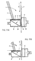
- FIG. 11A shows the area of the channel inlet 27 of a further embodiment of the invention in detail.
- This embodiment corresponds essentially to the embodiment according to FIG. 9, with the difference that the carrier material band 4 does not run over rollers which are embedded in the channel base surface, but rather the back of the carrier material band 4 is subjected to a vacuum in the suction region of the duct inlet, thereby ensuring that the carrier material band is not deflected by the gas flow arising at the top.
- a vacuum chamber 41 which is opposed, for example, by a porous plate 42 Back of the carrier tape 4 is open.
- a perforated plate 68 is arranged in the interior of the vacuum chamber and ensures a uniform outflow of the extracted gas or the extracted air.
- the channel inlet 27 is closed at the bottom by a suction box 37.
- the gas flow accelerated in the direction of flow B enters the interior of the suction box 37 through a filter mat 47, a metal mesh or the like, in which a diagonally arranged, perforated baffle plate 49 may also be present.
- This baffle plate is not absolutely necessary and can also be omitted if there is no formation of vortices within the suction box 37.
- baffle plate 49 The purpose of the baffle plate 49 is namely to prevent vortex formation within the suction box 37, so that a uniform suction is ensured over the entire dryer width.
- a lamellar seal 38 or a labyrinth seal is arranged, which closes the channel inlet as tightly as possible, but without contact, against the moving carrier material band 4.
- drying gas or drying air is fed into the interior of the drying channel through the inclined channel top surface 7.
- FIG. 11B shows the suction area of an embodiment which largely corresponds to the embodiment according to FIG. 11A, with the only difference that instead of the lamella seal, a doctor seal 43 is attached to the vertical outside of the suction box 37 and closes the channel inlet as tightly as possible against the carrier material strip 4.
- a vacuum chamber 41 On the back of the carrier material band 4 there is again a vacuum chamber 41, which prevents the carrier material band 4 from being deflected by the gas flow which arises at the top.
- FIG. 12A shows a schematic sectional view of an eighth embodiment of the drying device 1, in which the drying duct 2 has a vertically running duct cover surface 7 which runs parallel to the vertical duct base surface 3.
- the channel cover surface 7 consists of lined up, equally thick filter mats 26, which have different permeability to a gas or air.
- the different permeability is indicated by different hatching of the individual filter mats 26, in such a way that the filter mat near the sewer outlet is more hatched, corresponding to its lower permeability, and the hatching of the filter mats 26 decrease in the direction of the sewer inlet to indicate that the permeability of the filter mats increases counter to the running direction A of the carrier material band 33.
- the remaining components of the drying device which correspond to the components of the embodiments of the drying device according to FIGS. 9 and 11A, are given the same reference numbers as in FIGS. 9 and 11A.
- a suction box 37 with a filter mat 47 In front of the channel inlet 27 of the drying channel 2 there is a suction box 37 with a filter mat 47.
- the channel cross sections are constant over the length of the drying channel 2. Because of the different permeability of the filter mats 26, a different amount of gas / air flows through the individual filter mat 26, which is indicated by the size of the curved arrows P1 to P4, which are assigned to the individual filter mats 26. Air or gas flows from above into the drying duct 2 via the inflow box 39 with the filter mat 48.
- the increase in the amount of gas / air supplied in the direction of the duct inlet results in an acceleration of the flow against the direction of travel of the carrier material band 33.
- This acceleration or This increase in speed of the flow towards the channel inlet is indicated by the increasing speed arrows v i , which are drawn in parallel to the carrier material band 33.
- the lateral supply of drying gas or air through the channel cover surface 7 takes place via inflow channels 61 of the drying device 1.
- the ninth embodiment shown in FIG. 12B is the same as the eighth embodiment except for the top surface.
- the top surface 7 of the ninth embodiment has constant permeability over the channel length. Since the gas volume flow supplied via the cover surface increases in the direction of the channel inlet even with a constant permeability of the cover surface, the flow is accelerated counter to the running direction of the carrier material strip 33.
- the inflow and suction boxes are sealed against the carrier tape 33 by means of labyrinth seals 40 and 38, respectively, and a vacuum chamber 41 provides negative pressure on the back of the carrier tape 33 in the region of the channel inlet in order to deflect the tape at the front of the tape 33 due to the flow prevent.
- the channel cover surface 7 can also consist of filter mats of the same structure and consistency, but of different thicknesses, which are lined up, the thickness of the filter mats decreasing counter to the running direction of the carrier material band 33, i.e. in other words, the permeability of the filter mats increases in the direction of the channel inlet.
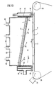
- FIG. 13 shows a tenth embodiment of the drying device according to the invention in section, in which the channel cover surface 7 converges towards the vertical channel base surface 3 in the direction of the channel outlet.
- the channel cover surface 7 is permeable to gas / air and consists of a continuous filter, but can also be made of filter mats strung together, as shown in FIG. 12A.
- the channel inlet of the drying channel 2 is larger than the channel outlet.
- the cross sections of the drying channel 2 are rectangular, the channel width decreasing linearly upwards from the channel inlet to the width of the channel outlet.
- To the side of the drying channel is an air space 69 of the drying device.
- inflow channels 62 are arranged through which drying gas, for example heated air, flows in and enters the drying channel 2 through the channel cover surface 7 in the direction of the arrows P1 to P4.
- the increasing size of the arrows P1 to P4 indicates that the flow of the drying gas within the drying channel 2 increases from bottom to top, in other words that the flow speed increases in the direction of the channel outlet.
- the carrier material strip 4 is guided around a deflection roller 35 which is opposite a slot die 34 in the 7 o'clock position with a small gap. Through the slot die 34, a liquid layer of vaporizable solvent components and non-vaporizable components is applied to the front of the carrier material strip 4, which runs vertically upwards through the duct inlet into the drying duct 2.
- the carrier material strip 4 runs over support rollers 6, which are arranged laterally at a short distance from the channel base 3.
- the channel inlet is closed by an inlet box 39 with a filter mat 48, and all or part of the drying gas flows through the inlet box 39 and the filter mat 48 in the direction of flow B upwards, in the same direction as the direction of travel A of the carrier material band 4, through the drying channel 2.
- the duct outlet is closed by a suction box 37 with a filter mat 47 through which the drying gas is sucked off.
- the drying duct 2 is sealed at the duct inlet and at the duct outlet by means of lamella seals 40 and 38 or labyrinth seals as tightly as possible, but without streaking, against the moving carrier material strip 4.
- the lamella seals 38, 40 are located on the vertical outer walls of the suction box 37 and the inflow box 39, which face the carrier material band 4.
- the carrier material strip 4 emerging from the channel outlet is guided over a deflection roller 36 and directed from the vertical direction in an obliquely downward direction for further processing.
- the flow rate at the channel inlet is set so high that the influence of gravity is overcome by the flow rate of the drying gas. This happens in such a way that on Channel inlet of the drying gas by appropriate measures on the inflow box 39, such as attaching the filter mat 48 and a perforated plate 70 inside the inflow box, the drying gas flows in already laminar. This allows the solvent vapors to be discharged upwards at the required speed. This avoids the risk of blown structures occurring on the coated front side of the carrier material strip 4.
- the drying channel 2, an upper run 65 and a lower run 66 of the carrier material strip 4 run horizontally.
- the flow direction B of the drying gas which flows through the inflow box 39 into the drying channel 2 and flows out through the suction box 37, is opposite to the running direction A of the lower run of the carrier material band 4 through the drying channel 2, and the flow is accelerated in the flow direction B. .
- This embodiment is used, for example, when applying a second layer S2 to a dried first layer S1 on the carrier material strip 4.
- the top of the upper run 65 is already provided with a dried first layer of liquid and is guided around by a revolving roller 63.
- a slot die 64 is arranged in the 11 o'clock position and at a short distance from the deflection roller 63.
- the second liquid becomes through the slot die 64 applied layer on the dried first liquid layer on the carrier material tape 4.
- the second liquid layer runs through the drying channel 2, hanging on the underside of the horizontally guided lower run 66.
- the carrier material strip 4 is guided below and along a horizontal channel ceiling 72 of the drying channel 2.
- a channel bottom 71 of the drying channel 2 converges in the flow direction B of the drying gas.
- the channel inlet of the drying channel 2 for the carrier material band 4 has a lower height than the channel outlet which the vertically oriented inflow box 39, which has a filter mat 48, closes.
- the channel inlet is closed by the suction box 37 and its filter mat 47. Both the inflow and the suction box carry labyrinth seals on their horizontal upper sides, which seal the channel outlet and the channel inlet against the lower run 66 of the carrier material strip 4.
- This embodiment of the drying duct is comparable in its arrangement and mode of operation to the right half of the embodiment according to FIG. 10, if it is taken into account that the drying duct 2 is arranged horizontally and not vertically, as in the embodiment according to FIG. 10, and that it is the application and drying of a second layer on a first layer of the carrier material band.
- the solution of a light-sensitive polymer material in an organic solvent is uniformly applied to an aluminum web 4 of 0.1 mm thickness pretreated for offset printing purposes at a running speed of 8 m / min by an appropriate coating method.
- the solution has a dynamic viscosity of 1.4 mPas and the thickness of the liquid film is 27 ⁇ m.
- the aluminum web runs into a drying device 1 according to one of the embodiments according to FIGS. 1 to 4 or 6.
- the duct outlet height h2 in the duct outlet is 2 cm
- the duct inlet height h1 in the duct inlet is 30 cm.
- the duct cover surface 7 is inclined at an angle of 13.1 ° to the web plane.
- the circulating air blower 12 is not switched on and the throttle valve 13 is closed.
- the performance of the suction fan 9 is adjusted so that at the entrance of the drying duct 2 there is an air speed of v 1 equal to 0.3 m / sec.
- the photosensitive layer of the aluminum web 4 obtained, which is subsequently made into printing plates, is very uniform in its thickness and in its optical appearance. With a reflected light densitometer, a uniform optical density of 1.47 is measured on the entire coated plate surface.
- a layer with a cloudy or mottled structure is obtained. Thin and thick spots with a surface area of 5 to 20 mm in diameter are distributed irregularly over the entire surface. The densitometric measurement does not result in a uniform optical density, but its size fluctuates between 1.43 and 1.50 depending on the measurement location.
- a vesicular film solution dissolved in an organic solvent, is applied to a polyester film 125 ⁇ m thick by a suitable coating process.
- the coating speed is 5 m / min.
- the solution has a dynamic viscosity of 5.5 mPas, the thickness of the applied liquid film is 40 ⁇ m.
- the liquid film is dried in the same way as described with reference to embodiment 1.
- the film is irradiated with UV light over a large area in a copier frame and then developed by briefly heating to 100 ° C.
- the resulting clouding of the film layer is uniform over the entire surface.
- the coating and the drying process are similar to those in the exemplary embodiment 2, but in a different way, the suction fan 9 is not switched on in the drying device 1.
- the actual drying of the liquid film takes place, as in comparative example 1, only in the downstream nozzle dryer.
- a solution of a light-sensitive polymer material is uniformly applied to an aluminum web pretreated for offset printing purposes as a carrier material strip 4, with a thickness of 0.3 mm, at a belt speed of 15 m / min.
- the liquid film is 33 ⁇ m thick.
- the solution has a dynamic viscosity of 2.9 mPas.
- a drying device 1 as shown in FIG. 2 is used.
- the channel cover surface 7 is designed as a porous filter and inclined at an angle of 4.3 ° against the aluminum web or the carrier material strip 4.
- the circulating air blower 12 is in operation and the throttle valve 13 is open.
- the position of the throttle valve 14 is selected so that an air volume flow of 1000 m3 / h fresh air is sucked into the drying chamber 5.
- An equal amount of air is sucked out of the drying duct 2 by the suction fan 12, so that there is no accumulation of evaporated solvent in the drying air. Due to the exact setting of the air volume flow on the suction fan 12 achieved that the inflow velocity v1 is almost zero.
- the channel length of drying channel 2 is approx. 5.7 m.
- channel lengths of the drying channels of 10 to 12 m are used, whereby the channel length and the volume flow of the drying gas include depend on the throughput speed of the carrier material strip through the drying device.
Landscapes
- Engineering & Computer Science (AREA)
- Mechanical Engineering (AREA)
- General Engineering & Computer Science (AREA)
- Textile Engineering (AREA)
- Drying Of Solid Materials (AREA)
- Application Of Or Painting With Fluid Materials (AREA)
- Coating Apparatus (AREA)
Priority Applications (1)
| Application Number | Priority Date | Filing Date | Title |
|---|---|---|---|
| AT89108281T ATE75026T1 (de) | 1988-05-13 | 1989-05-09 | Verfahren und vorrichtung zum trocknen einer auf einem bewegten traegermaterial aufgebrachten fluessigkeitsschicht. |
Applications Claiming Priority (4)
| Application Number | Priority Date | Filing Date | Title |
|---|---|---|---|
| DE3816414A DE3816414A1 (de) | 1988-05-13 | 1988-05-13 | Verfahren und vorrichtung zum trocknen einer auf einem bewegten traegermaterial aufgebrachten fluessigkeitsschicht |
| DE3816414 | 1988-05-13 | ||
| DE3900957 | 1989-01-14 | ||
| DE3900957A DE3900957A1 (de) | 1989-01-14 | 1989-01-14 | Verfahren und vorrichtung zum trocknen einer auf einem durch eine trocknungszone bewegten traegermaterial aufgebrachten fluessigkeitsschicht |
Publications (3)
| Publication Number | Publication Date |
|---|---|
| EP0341646A2 true EP0341646A2 (fr) | 1989-11-15 |
| EP0341646A3 EP0341646A3 (en) | 1990-05-02 |
| EP0341646B1 EP0341646B1 (fr) | 1992-04-15 |
Family
ID=25868083
Family Applications (1)
| Application Number | Title | Priority Date | Filing Date |
|---|---|---|---|
| EP89108281A Expired - Lifetime EP0341646B1 (fr) | 1988-05-13 | 1989-05-09 | Procédé et dispositif de séchage d'une couche liquide appliquée sur un matériau de support en mouvement |
Country Status (10)
| Country | Link |
|---|---|
| US (1) | US4999927A (fr) |
| EP (1) | EP0341646B1 (fr) |
| JP (1) | JP3013044B2 (fr) |
| KR (1) | KR0135080B1 (fr) |
| AU (1) | AU624817B2 (fr) |
| BR (1) | BR8902224A (fr) |
| CA (1) | CA1336533C (fr) |
| DE (1) | DE58901137D1 (fr) |
| ES (1) | ES2030935T3 (fr) |
| FI (1) | FI892292A7 (fr) |
Cited By (3)
| Publication number | Priority date | Publication date | Assignee | Title |
|---|---|---|---|---|
| WO1993019337A3 (fr) * | 1992-03-19 | 1993-11-25 | Schmidt Gmbh Reinhart | Dispositif pour secher des produits se trouvant sur une brande transporteuse en mouvement, notamment les parties gommees d'enveloppes |
| DE4236299C2 (de) * | 1992-10-28 | 2003-03-06 | Emtec Magnetics Gmbh | Abdichtvorrichtung am Einlauf und/oder Auslauf eines Schwebetrockners für Warenbahnen |
| CN112414071A (zh) * | 2020-11-21 | 2021-02-26 | 苏州宸浩纺织科技有限公司 | 一种用于纺织布料的烘干设备 |
Families Citing this family (45)
| Publication number | Priority date | Publication date | Assignee | Title |
|---|---|---|---|---|
| US5158846A (en) * | 1990-10-29 | 1992-10-27 | Olin Corporation | Electrostatic color printing system utilizing an image transfer belt |
| US5085580A (en) * | 1990-11-30 | 1992-02-04 | Glasstech, Inc. | Preheater for flat glass sheets |
| DE4301023C3 (de) * | 1993-01-16 | 2001-07-26 | V I B Systems Gmbh | Vorrichtung zum Erhöhen von Glanz und/oder Glätte einer Papierbahn |
| US5380644A (en) * | 1993-08-10 | 1995-01-10 | Minnesota Mining And Manufacturing Company | Additive for the reduction of mottle in photothermographic and thermographic elements |
| US6293196B1 (en) | 1993-10-06 | 2001-09-25 | Howard W. DeMoore | High velocity, hot air dryer and extractor |
| US5532121A (en) * | 1995-03-24 | 1996-07-02 | Minnesota Mining And Manufacturing Company | Mottle reducing agent for photothermographic and thermographic elements |
| US5694701A (en) * | 1996-09-04 | 1997-12-09 | Minnesota Mining And Manufacturing Company | Coated substrate drying system |
| US5581905A (en) * | 1995-09-18 | 1996-12-10 | Minnesota Mining And Manufacturing Company | Coated substrate drying system |
| KR100456683B1 (ko) * | 1995-09-18 | 2005-01-15 | 미네소타 마이닝 앤드 매뉴팩춰링 캄파니 | 응축 기구를 포함하는 성분 분리 시스템 |
| US5621983A (en) * | 1996-03-29 | 1997-04-22 | Minnesota Mining And Manufacturing Company | Apparatus and method for deckeling excess air when drying a coating on a substrate |
| US6015593A (en) * | 1996-03-29 | 2000-01-18 | 3M Innovative Properties Company | Method for drying a coating on a substrate and reducing mottle |
| WO1997037182A1 (fr) * | 1996-03-29 | 1997-10-09 | Minnesota Mining And Manufacturing Company | Appareil et technique de sechage d'un revetement sur un substrat en faisant appel a plusieurs sous-zones de sechage |
| US6018886A (en) * | 1996-06-25 | 2000-02-01 | Eastman Kodak Company | Effect of air baffle design on mottle in solvent coatings |
| US5813133A (en) * | 1996-09-04 | 1998-09-29 | Minnesota Mining And Manufacturing Company | Coated substrate drying system with magnetic particle orientation |
| USRE38412E1 (en) | 1996-09-04 | 2004-02-03 | Imation Corp. | Coated substrate drying system with magnetic particle orientation |
| US5906862A (en) * | 1997-04-02 | 1999-05-25 | Minnesota Mining And Manufacturing Company | Apparatus and method for drying a coating on a substrate |
| US6047151A (en) * | 1998-05-06 | 2000-04-04 | Imation Corp. | Drying system and method for an electrophotographic imaging system |
| US6256904B1 (en) | 1998-05-06 | 2001-07-10 | Imation Corp. | Controlling float height of moving substrate over curved plate |
| US6134808A (en) * | 1998-05-18 | 2000-10-24 | Minnesota Mining And Manufacturing Company | Gap drying with insulation layer between substrate and heated platen |
| MXPA03002502A (es) * | 2000-09-24 | 2004-05-05 | 3M Innovative Properties Co | Metodo y aparato de extrusion para fabricar peliculas microporosas. |
| US6780470B2 (en) * | 2001-07-18 | 2004-08-24 | Fuji Photo Film Co., Ltd. | Method of coating a web with a solution |
| US6785982B2 (en) | 2002-06-07 | 2004-09-07 | Eastman Kodak Company | Drying apparatus and method for drying coated webs |
| US6715942B1 (en) * | 2002-12-02 | 2004-04-06 | Eastman Kodak Company | Photographic processing drum having a circular drying cylinder |
| EP1462746B1 (fr) * | 2003-03-26 | 2013-05-08 | FUJIFILM Corporation | Procédé et dispositif de séchage pour une couche de revêtement |
| US6954994B1 (en) * | 2004-06-30 | 2005-10-18 | Hewlett-Packard Development Company, L.P. | Moisture removal mechanism |
| US7201563B2 (en) * | 2004-09-27 | 2007-04-10 | Studebaker Enterprises, Inc. | Louvered fan grille for a shrouded floor drying fan |
| CN101035455A (zh) * | 2005-07-26 | 2007-09-12 | 三菱电机株式会社 | 手干燥装置 |
| WO2007015297A1 (fr) * | 2005-08-03 | 2007-02-08 | Mitsubishi Denki Kabushiki Kaisha | Seche-mains |
| JP4796352B2 (ja) * | 2005-08-03 | 2011-10-19 | パナソニック株式会社 | 熱処理装置 |
| US7614160B2 (en) * | 2005-08-18 | 2009-11-10 | Mitsubishi Denki Kabushiki Kaisha | Hand drying apparatus |
| US20070201933A1 (en) * | 2006-02-24 | 2007-08-30 | Park Namjeon | Feeding system for image forming machine |
| US20070199206A1 (en) * | 2006-02-24 | 2007-08-30 | Park Namjeon | Drying system for image forming machine |
| US20070200881A1 (en) * | 2006-02-24 | 2007-08-30 | Park Namjeon | Height adjustment system for image forming machine |
| US7905947B2 (en) * | 2006-05-24 | 2011-03-15 | L.C. Eldridge Sales Co., Ltd. | Method and apparatus for removing contaminates from air |
| CN101801174B (zh) * | 2007-07-15 | 2012-02-15 | 格林百奥生态材料科技(上海)有限公司 | 可干燥木产品的太阳能温室 |
| JP5086721B2 (ja) * | 2007-07-30 | 2012-11-28 | リンテック株式会社 | ウェブの加熱冷却装置及びウェブの加熱冷却方法 |
| TWI493070B (zh) * | 2012-12-07 | 2015-07-21 | Metal Ind Res & Dev Ct | Gas diffusion chamber |
| DE102013223150A1 (de) | 2013-11-13 | 2015-05-28 | Sandvik Materials Technology Deutschland Gmbh | Trockner und Verfahren zum Trocknen von flächigen Materialien |
| JP6531423B2 (ja) * | 2015-02-24 | 2019-06-19 | セイコーエプソン株式会社 | 印刷装置 |
| CN108290182B (zh) * | 2015-10-12 | 2021-11-02 | 3M创新有限公司 | 逐层涂覆装置和方法 |
| JP6595946B2 (ja) * | 2016-04-04 | 2019-10-23 | 株式会社市金工業社 | 塗工装置 |
| WO2018146381A1 (fr) * | 2017-02-08 | 2018-08-16 | Beneq Oy | Procédé et appareil de revêtement |
| CN107144115A (zh) * | 2017-07-04 | 2017-09-08 | 金寨县云凡绿色中药材有限责任公司 | 一种用于灵芝加工的烘干装置 |
| DE102017129017A1 (de) * | 2017-12-06 | 2019-06-06 | Heraeus Noblelight Gmbh | Verfahren zum Trocknen eines Substrats, Trocknermodul zur Durchführung des Verfahrens sowie Trocknersystem |
| CN111156814B (zh) * | 2018-11-07 | 2024-03-29 | 中石化石油工程技术服务股份有限公司 | 一种内循环岩屑物料除湿装置 |
Family Cites Families (13)
| Publication number | Priority date | Publication date | Assignee | Title |
|---|---|---|---|---|
| US2144919A (en) * | 1937-06-24 | 1939-01-24 | Andrews And Goodrich Inc | Apparatus for and method of drying web material |
| US2775046A (en) * | 1949-05-31 | 1956-12-25 | Sucker Gmbh Geb | Methods and apparatus for the processing of textile materials |
| US3012335A (en) * | 1957-11-16 | 1961-12-12 | Svenska Flaektfabriken Ab | Treating web-like material by a gaseous medium |
| GB877266A (en) * | 1959-02-13 | 1961-09-13 | John Harold Flynn | Method of drying coated webs |
| US3106460A (en) * | 1959-05-01 | 1963-10-08 | Calico Printers Ass Ltd | Process for removing organic solvent from wet material |
| US3183604A (en) * | 1961-01-05 | 1965-05-18 | Gen Electric | Apparatus and process for removing solvents from coatings on metal |
| US3183605A (en) * | 1961-12-27 | 1965-05-18 | Gen Electric | Apparatus for coating metals |
| DE1604865B1 (de) * | 1966-10-31 | 1971-06-03 | Elektro Isolier Ind Wahn Wilhe | Anlage fuer die katalytische Verbrennung brennbarer Bestandteile aus Abgasen,z.B. von Lackeinbrennoefen |
| GB1216267A (en) * | 1968-02-09 | 1970-12-16 | Wilkins & Mitchell Ltd | Improvements in or relating to presses |
| GB1239094A (fr) * | 1969-06-30 | 1971-07-14 | ||
| US4589843A (en) * | 1976-04-07 | 1986-05-20 | Smith Thomas M | Infra-red irradiation |
| AT362227B (de) * | 1979-07-02 | 1981-04-27 | Andritz Ag Maschf | Materialbahntrockner |
| JPS5723113A (en) * | 1980-07-17 | 1982-02-06 | Fanuc Ltd | Numerical controller |
-
1989
- 1989-05-09 US US07/349,227 patent/US4999927A/en not_active Expired - Lifetime
- 1989-05-09 DE DE8989108281T patent/DE58901137D1/de not_active Expired - Fee Related
- 1989-05-09 ES ES198989108281T patent/ES2030935T3/es not_active Expired - Lifetime
- 1989-05-09 EP EP89108281A patent/EP0341646B1/fr not_active Expired - Lifetime
- 1989-05-09 CA CA000599057A patent/CA1336533C/fr not_active Expired - Fee Related
- 1989-05-10 AU AU34725/89A patent/AU624817B2/en not_active Ceased
- 1989-05-10 KR KR1019890006218A patent/KR0135080B1/ko not_active Expired - Fee Related
- 1989-05-11 FI FI892292A patent/FI892292A7/fi not_active IP Right Cessation
- 1989-05-12 BR BR898902224A patent/BR8902224A/pt not_active IP Right Cessation
- 1989-05-15 JP JP1118850A patent/JP3013044B2/ja not_active Expired - Fee Related
Cited By (4)
| Publication number | Priority date | Publication date | Assignee | Title |
|---|---|---|---|---|
| WO1993019337A3 (fr) * | 1992-03-19 | 1993-11-25 | Schmidt Gmbh Reinhart | Dispositif pour secher des produits se trouvant sur une brande transporteuse en mouvement, notamment les parties gommees d'enveloppes |
| DE4236299C2 (de) * | 1992-10-28 | 2003-03-06 | Emtec Magnetics Gmbh | Abdichtvorrichtung am Einlauf und/oder Auslauf eines Schwebetrockners für Warenbahnen |
| CN112414071A (zh) * | 2020-11-21 | 2021-02-26 | 苏州宸浩纺织科技有限公司 | 一种用于纺织布料的烘干设备 |
| CN112414071B (zh) * | 2020-11-21 | 2021-08-27 | 苏州宸浩纺织科技有限公司 | 一种用于纺织布料的烘干设备 |
Also Published As
| Publication number | Publication date |
|---|---|
| FI892292A7 (fi) | 1989-11-14 |
| EP0341646B1 (fr) | 1992-04-15 |
| JPH0217966A (ja) | 1990-01-22 |
| JP3013044B2 (ja) | 2000-02-28 |
| CA1336533C (fr) | 1995-08-08 |
| US4999927A (en) | 1991-03-19 |
| AU3472589A (en) | 1989-11-16 |
| EP0341646A3 (en) | 1990-05-02 |
| KR0135080B1 (ko) | 1998-06-15 |
| BR8902224A (pt) | 1990-01-02 |
| AU624817B2 (en) | 1992-06-25 |
| FI892292A0 (fi) | 1989-05-11 |
| KR890017515A (ko) | 1989-12-16 |
| DE58901137D1 (de) | 1992-05-21 |
| ES2030935T3 (es) | 1992-11-16 |
Similar Documents
| Publication | Publication Date | Title |
|---|---|---|
| EP0341646B1 (fr) | Procédé et dispositif de séchage d'une couche liquide appliquée sur un matériau de support en mouvement | |
| EP0414125B1 (fr) | Dispositif pour le séchage d'une couche liquide appliquée sur un substrat en mouvement | |
| DE69219707T2 (de) | Unterdruckdüsenanordnung zur Behandlung von Bahnen | |
| EP0528372B1 (fr) | Dispositif pour le guidage sans contact d'une bande continue revêtue | |
| DE60225332T2 (de) | Verfahren und vorrichtung zum vorhanggiessen | |
| DE2253170C2 (de) | Verfahren und Vorrichtung zum Behandeln einer frei schwebend geführten Materialbahn | |
| US4287240A (en) | Coating apparatus provided with a protective shield | |
| DE69026097T2 (de) | Vorhangbeschichter | |
| DE69330413T2 (de) | Verfahren zum Lufttrocknen von freigeführten Materialbahnen and Lufttrockner zur Durchführung des Verfahrens | |
| DE3148578A1 (de) | Verfahren und vorrichtung in der pressen- oder trockenpartie einer papiermaschine | |
| DE69701134T2 (de) | Vorrichtung und verfahren zur trocknung einer beschichtigung auf einem substrat | |
| DE69723838T2 (de) | Verfahren und vorrichtung zur prälltrocknung und/oder durchlufttrocknung einer papierbahn oder dergleichen | |
| DE69718851T2 (de) | Verfahren zum Trocknen eines sich bewegenden, beschichteten bahnförmigen Materials unter Vermeidung von Fleckenbildung bei der Beschichtung mit Lösungsmitteln | |
| DE2935373A1 (de) | Vorrichtung zur waermebehandlung von flachen bahnfoermigen warenbahnen | |
| DE3884628T2 (de) | Vorrichtung zum halten der kanten einer bahn an einem trocknerfilz. | |
| DE1474239B2 (de) | Verfahren und einrichtung zur stabilisierung der lage unter wirkung eines blasmittels schwebend gefuehrter warenbahnen | |
| DE2443395B2 (de) | Vorrichtung zum Wärmebehandeln von flachen Materialbahnen mittels eines strömenden Mediums im Kreislaufverfahren | |
| DE102017124280A1 (de) | Vorhang-Auftragswerk und Verfahren zum Auftragen eines Auftragsmediums | |
| DE8915647U1 (de) | Vorrichtung zur Behandlung von Monofilen | |
| EP0906789B1 (fr) | Procédé et appareil pour le revêtement par rideau d'un support en movement | |
| DE68924321T2 (de) | Beschichtungsvorrichtung für Gewebe. | |
| DE3816414A1 (de) | Verfahren und vorrichtung zum trocknen einer auf einem bewegten traegermaterial aufgebrachten fluessigkeitsschicht | |
| DE3900957A1 (de) | Verfahren und vorrichtung zum trocknen einer auf einem durch eine trocknungszone bewegten traegermaterial aufgebrachten fluessigkeitsschicht | |
| DE10246901C1 (de) | Einrichtung und Verfahren zum Fixieren eines Tonerbildes durch Lösemitteldampf unter Reduzierung des Lösemittelaustrages | |
| DE3942029A1 (de) | Vorrichtung zum tragen, umlenken und spreizen einer bahn |
Legal Events
| Date | Code | Title | Description |
|---|---|---|---|
| PUAI | Public reference made under article 153(3) epc to a published international application that has entered the european phase |
Free format text: ORIGINAL CODE: 0009012 |
|
| AK | Designated contracting states |
Kind code of ref document: A2 Designated state(s): AT BE CH DE ES FR GB IT LI NL SE |
|
| PUAL | Search report despatched |
Free format text: ORIGINAL CODE: 0009013 |
|
| AK | Designated contracting states |
Kind code of ref document: A3 Designated state(s): AT BE CH DE ES FR GB IT LI NL SE |
|
| 17P | Request for examination filed |
Effective date: 19901005 |
|
| 17Q | First examination report despatched |
Effective date: 19910208 |
|
| GRAA | (expected) grant |
Free format text: ORIGINAL CODE: 0009210 |
|
| AK | Designated contracting states |
Kind code of ref document: B1 Designated state(s): AT BE CH DE ES FR GB IT LI NL SE |
|
| REF | Corresponds to: |
Ref document number: 75026 Country of ref document: AT Date of ref document: 19920515 Kind code of ref document: T |
|
| REF | Corresponds to: |
Ref document number: 58901137 Country of ref document: DE Date of ref document: 19920521 |
|
| ET | Fr: translation filed | ||
| ITF | It: translation for a ep patent filed | ||
| GBT | Gb: translation of ep patent filed (gb section 77(6)(a)/1977) | ||
| REG | Reference to a national code |
Ref country code: ES Ref legal event code: FG2A Ref document number: 2030935 Country of ref document: ES Kind code of ref document: T3 |
|
| PLBE | No opposition filed within time limit |
Free format text: ORIGINAL CODE: 0009261 |
|
| STAA | Information on the status of an ep patent application or granted ep patent |
Free format text: STATUS: NO OPPOSITION FILED WITHIN TIME LIMIT |
|
| 26N | No opposition filed | ||
| PGFP | Annual fee paid to national office [announced via postgrant information from national office to epo] |
Ref country code: SE Payment date: 19940427 Year of fee payment: 6 |
|
| EAL | Se: european patent in force in sweden |
Ref document number: 89108281.0 |
|
| PG25 | Lapsed in a contracting state [announced via postgrant information from national office to epo] |
Ref country code: SE Effective date: 19950510 |
|
| EUG | Se: european patent has lapsed |
Ref document number: 89108281.0 |
|
| PGFP | Annual fee paid to national office [announced via postgrant information from national office to epo] |
Ref country code: BE Payment date: 19990409 Year of fee payment: 11 |
|
| PGFP | Annual fee paid to national office [announced via postgrant information from national office to epo] |
Ref country code: CH Payment date: 19990412 Year of fee payment: 11 |
|
| PGFP | Annual fee paid to national office [announced via postgrant information from national office to epo] |
Ref country code: AT Payment date: 19990423 Year of fee payment: 11 |
|
| PGFP | Annual fee paid to national office [announced via postgrant information from national office to epo] |
Ref country code: ES Payment date: 19990510 Year of fee payment: 11 |
|
| PG25 | Lapsed in a contracting state [announced via postgrant information from national office to epo] |
Ref country code: AT Free format text: LAPSE BECAUSE OF NON-PAYMENT OF DUE FEES Effective date: 20000509 |
|
| PG25 | Lapsed in a contracting state [announced via postgrant information from national office to epo] |
Ref country code: ES Free format text: THE PATENT HAS BEEN ANNULLED BY A DECISION OF A NATIONAL AUTHORITY Effective date: 20000510 |
|
| PG25 | Lapsed in a contracting state [announced via postgrant information from national office to epo] |
Ref country code: LI Free format text: LAPSE BECAUSE OF NON-PAYMENT OF DUE FEES Effective date: 20000531 Ref country code: CH Free format text: LAPSE BECAUSE OF NON-PAYMENT OF DUE FEES Effective date: 20000531 Ref country code: BE Free format text: LAPSE BECAUSE OF NON-PAYMENT OF DUE FEES Effective date: 20000531 |
|
| BERE | Be: lapsed |
Owner name: HOECHST A.G. Effective date: 20000531 |
|
| REG | Reference to a national code |
Ref country code: CH Ref legal event code: PL |
|
| REG | Reference to a national code |
Ref country code: GB Ref legal event code: IF02 |
|
| REG | Reference to a national code |
Ref country code: ES Ref legal event code: FD2A Effective date: 20020304 |
|
| REG | Reference to a national code |
Ref country code: FR Ref legal event code: TP |
|
| REG | Reference to a national code |
Ref country code: GB Ref legal event code: 732E |
|
| PGFP | Annual fee paid to national office [announced via postgrant information from national office to epo] |
Ref country code: FR Payment date: 20030418 Year of fee payment: 15 |
|
| PGFP | Annual fee paid to national office [announced via postgrant information from national office to epo] |
Ref country code: NL Payment date: 20030423 Year of fee payment: 15 Ref country code: DE Payment date: 20030423 Year of fee payment: 15 |
|
| PGFP | Annual fee paid to national office [announced via postgrant information from national office to epo] |
Ref country code: GB Payment date: 20030424 Year of fee payment: 15 |
|
| PG25 | Lapsed in a contracting state [announced via postgrant information from national office to epo] |
Ref country code: GB Free format text: LAPSE BECAUSE OF NON-PAYMENT OF DUE FEES Effective date: 20040509 |
|
| PG25 | Lapsed in a contracting state [announced via postgrant information from national office to epo] |
Ref country code: NL Free format text: LAPSE BECAUSE OF NON-PAYMENT OF DUE FEES Effective date: 20041201 Ref country code: DE Free format text: LAPSE BECAUSE OF NON-PAYMENT OF DUE FEES Effective date: 20041201 |
|
| GBPC | Gb: european patent ceased through non-payment of renewal fee |
Effective date: 20040509 |
|
| PG25 | Lapsed in a contracting state [announced via postgrant information from national office to epo] |
Ref country code: FR Free format text: LAPSE BECAUSE OF NON-PAYMENT OF DUE FEES Effective date: 20050131 |
|
| NLV4 | Nl: lapsed or anulled due to non-payment of the annual fee |
Effective date: 20041201 |
|
| REG | Reference to a national code |
Ref country code: FR Ref legal event code: ST |
|
| PG25 | Lapsed in a contracting state [announced via postgrant information from national office to epo] |
Ref country code: IT Free format text: LAPSE BECAUSE OF NON-PAYMENT OF DUE FEES;WARNING: LAPSES OF ITALIAN PATENTS WITH EFFECTIVE DATE BEFORE 2007 MAY HAVE OCCURRED AT ANY TIME BEFORE 2007. THE CORRECT EFFECTIVE DATE MAY BE DIFFERENT FROM THE ONE RECORDED. Effective date: 20050509 |