EP0343368B1 - Im Rohrende von Wärmewechslern fernbediente Hülseneinbringvorrichtung - Google Patents
Im Rohrende von Wärmewechslern fernbediente Hülseneinbringvorrichtung Download PDFInfo
- Publication number
- EP0343368B1 EP0343368B1 EP89106831A EP89106831A EP0343368B1 EP 0343368 B1 EP0343368 B1 EP 0343368B1 EP 89106831 A EP89106831 A EP 89106831A EP 89106831 A EP89106831 A EP 89106831A EP 0343368 B1 EP0343368 B1 EP 0343368B1
- Authority
- EP
- European Patent Office
- Prior art keywords
- tube
- sleeve
- machine according
- tools
- flexible
- Prior art date
- Legal status (The legal status is an assumption and is not a legal conclusion. Google has not performed a legal analysis and makes no representation as to the accuracy of the status listed.)
- Expired - Lifetime
Links
- XLYOFNOQVPJJNP-UHFFFAOYSA-N water Substances O XLYOFNOQVPJJNP-UHFFFAOYSA-N 0.000 claims description 30
- 238000003466 welding Methods 0.000 claims description 9
- 239000002245 particle Substances 0.000 claims description 7
- 239000000523 sample Substances 0.000 claims description 7
- 238000003032 molecular docking Methods 0.000 claims description 6
- 238000004140 cleaning Methods 0.000 claims description 5
- 239000004033 plastic Substances 0.000 claims description 5
- 229920003023 plastic Polymers 0.000 claims description 5
- 230000000694 effects Effects 0.000 claims description 3
- 238000007689 inspection Methods 0.000 claims description 3
- 238000000034 method Methods 0.000 claims description 3
- 238000002592 echocardiography Methods 0.000 claims description 2
- 230000005611 electricity Effects 0.000 claims description 2
- 239000000463 material Substances 0.000 claims description 2
- 238000005096 rolling process Methods 0.000 claims 5
- 239000004952 Polyamide Substances 0.000 description 3
- 229920002647 polyamide Polymers 0.000 description 3
- 230000003416 augmentation Effects 0.000 description 2
- 230000000903 blocking effect Effects 0.000 description 2
- 230000008878 coupling Effects 0.000 description 2
- 238000010168 coupling process Methods 0.000 description 2
- 238000005859 coupling reaction Methods 0.000 description 2
- 230000002093 peripheral effect Effects 0.000 description 2
- 229910000760 Hardened steel Inorganic materials 0.000 description 1
- LRUUNMYPIBZBQH-UHFFFAOYSA-N Methazole Chemical compound O=C1N(C)C(=O)ON1C1=CC=C(Cl)C(Cl)=C1 LRUUNMYPIBZBQH-UHFFFAOYSA-N 0.000 description 1
- 239000004962 Polyamide-imide Substances 0.000 description 1
- 239000004698 Polyethylene Substances 0.000 description 1
- 229910000831 Steel Inorganic materials 0.000 description 1
- 230000007797 corrosion Effects 0.000 description 1
- 238000005260 corrosion Methods 0.000 description 1
- 238000007599 discharging Methods 0.000 description 1
- 238000006073 displacement reaction Methods 0.000 description 1
- 239000012153 distilled water Substances 0.000 description 1
- 230000005489 elastic deformation Effects 0.000 description 1
- 239000012530 fluid Substances 0.000 description 1
- 238000010438 heat treatment Methods 0.000 description 1
- 238000009434 installation Methods 0.000 description 1
- 239000002184 metal Substances 0.000 description 1
- 238000012544 monitoring process Methods 0.000 description 1
- 230000035515 penetration Effects 0.000 description 1
- 229920002312 polyamide-imide Polymers 0.000 description 1
- -1 polyethylene Polymers 0.000 description 1
- 229920000573 polyethylene Polymers 0.000 description 1
- 229920002635 polyurethane Polymers 0.000 description 1
- 239000004814 polyurethane Substances 0.000 description 1
- 125000006850 spacer group Chemical group 0.000 description 1
- 239000010959 steel Substances 0.000 description 1
- 239000012815 thermoplastic material Substances 0.000 description 1
Images


Classifications
-
- B—PERFORMING OPERATIONS; TRANSPORTING
- B23—MACHINE TOOLS; METAL-WORKING NOT OTHERWISE PROVIDED FOR
- B23P—METAL-WORKING NOT OTHERWISE PROVIDED FOR; COMBINED OPERATIONS; UNIVERSAL MACHINE TOOLS
- B23P19/00—Machines for simply fitting together or separating metal parts or objects, or metal and non-metal parts, whether or not involving some deformation; Tools or devices therefor so far as not provided for in other classes
- B23P19/04—Machines for simply fitting together or separating metal parts or objects, or metal and non-metal parts, whether or not involving some deformation; Tools or devices therefor so far as not provided for in other classes for assembling or disassembling parts
-
- F—MECHANICAL ENGINEERING; LIGHTING; HEATING; WEAPONS; BLASTING
- F22—STEAM GENERATION
- F22B—METHODS OF STEAM GENERATION; STEAM BOILERS
- F22B37/00—Component parts or details of steam boilers
- F22B37/002—Component parts or details of steam boilers specially adapted for nuclear steam generators, e.g. maintenance, repairing or inspecting equipment not otherwise provided for
- F22B37/003—Maintenance, repairing or inspecting equipment positioned in or via the headers
-
- B—PERFORMING OPERATIONS; TRANSPORTING
- B23—MACHINE TOOLS; METAL-WORKING NOT OTHERWISE PROVIDED FOR
- B23Q—DETAILS, COMPONENTS, OR ACCESSORIES FOR MACHINE TOOLS, e.g. ARRANGEMENTS FOR COPYING OR CONTROLLING; MACHINE TOOLS IN GENERAL CHARACTERISED BY THE CONSTRUCTION OF PARTICULAR DETAILS OR COMPONENTS; COMBINATIONS OR ASSOCIATIONS OF METAL-WORKING MACHINES, NOT DIRECTED TO A PARTICULAR RESULT
- B23Q1/00—Members which are comprised in the general build-up of a form of machine, particularly relatively large fixed members
- B23Q1/0009—Energy-transferring means or control lines for movable machine parts; Control panels or boxes; Control parts
-
- B—PERFORMING OPERATIONS; TRANSPORTING
- B23—MACHINE TOOLS; METAL-WORKING NOT OTHERWISE PROVIDED FOR
- B23Q—DETAILS, COMPONENTS, OR ACCESSORIES FOR MACHINE TOOLS, e.g. ARRANGEMENTS FOR COPYING OR CONTROLLING; MACHINE TOOLS IN GENERAL CHARACTERISED BY THE CONSTRUCTION OF PARTICULAR DETAILS OR COMPONENTS; COMBINATIONS OR ASSOCIATIONS OF METAL-WORKING MACHINES, NOT DIRECTED TO A PARTICULAR RESULT
- B23Q5/00—Driving or feeding mechanisms; Control arrangements therefor
- B23Q5/02—Driving main working members
- B23Q5/04—Driving main working members rotary shafts, e.g. working-spindles
- B23Q5/12—Mechanical drives with means for varying the speed ratio
- B23Q5/14—Mechanical drives with means for varying the speed ratio step-by-step
-
- F—MECHANICAL ENGINEERING; LIGHTING; HEATING; WEAPONS; BLASTING
- F28—HEAT EXCHANGE IN GENERAL
- F28F—DETAILS OF HEAT-EXCHANGE AND HEAT-TRANSFER APPARATUS, OF GENERAL APPLICATION
- F28F11/00—Arrangements for sealing leaky tubes and conduits
- F28F11/02—Arrangements for sealing leaky tubes and conduits using obturating elements, e.g. washers, inserted and operated independently of each other
-
- G—PHYSICS
- G01—MEASURING; TESTING
- G01N—INVESTIGATING OR ANALYSING MATERIALS BY DETERMINING THEIR CHEMICAL OR PHYSICAL PROPERTIES
- G01N2291/00—Indexing codes associated with group G01N29/00
- G01N2291/04—Wave modes and trajectories
- G01N2291/044—Internal reflections (echoes), e.g. on walls or defects
-
- Y—GENERAL TAGGING OF NEW TECHNOLOGICAL DEVELOPMENTS; GENERAL TAGGING OF CROSS-SECTIONAL TECHNOLOGIES SPANNING OVER SEVERAL SECTIONS OF THE IPC; TECHNICAL SUBJECTS COVERED BY FORMER USPC CROSS-REFERENCE ART COLLECTIONS [XRACs] AND DIGESTS
- Y10—TECHNICAL SUBJECTS COVERED BY FORMER USPC
- Y10T—TECHNICAL SUBJECTS COVERED BY FORMER US CLASSIFICATION
- Y10T29/00—Metal working
- Y10T29/49—Method of mechanical manufacture
- Y10T29/4935—Heat exchanger or boiler making
- Y10T29/49352—Repairing, converting, servicing or salvaging
-
- Y—GENERAL TAGGING OF NEW TECHNOLOGICAL DEVELOPMENTS; GENERAL TAGGING OF CROSS-SECTIONAL TECHNOLOGIES SPANNING OVER SEVERAL SECTIONS OF THE IPC; TECHNICAL SUBJECTS COVERED BY FORMER USPC CROSS-REFERENCE ART COLLECTIONS [XRACs] AND DIGESTS
- Y10—TECHNICAL SUBJECTS COVERED BY FORMER USPC
- Y10T—TECHNICAL SUBJECTS COVERED BY FORMER US CLASSIFICATION
- Y10T29/00—Metal working
- Y10T29/49—Method of mechanical manufacture
- Y10T29/4935—Heat exchanger or boiler making
- Y10T29/49373—Tube joint and tube plate structure
-
- Y—GENERAL TAGGING OF NEW TECHNOLOGICAL DEVELOPMENTS; GENERAL TAGGING OF CROSS-SECTIONAL TECHNOLOGIES SPANNING OVER SEVERAL SECTIONS OF THE IPC; TECHNICAL SUBJECTS COVERED BY FORMER USPC CROSS-REFERENCE ART COLLECTIONS [XRACs] AND DIGESTS
- Y10—TECHNICAL SUBJECTS COVERED BY FORMER USPC
- Y10T—TECHNICAL SUBJECTS COVERED BY FORMER US CLASSIFICATION
- Y10T29/00—Metal working
- Y10T29/53—Means to assemble or disassemble
- Y10T29/531—Nuclear device
-
- Y—GENERAL TAGGING OF NEW TECHNOLOGICAL DEVELOPMENTS; GENERAL TAGGING OF CROSS-SECTIONAL TECHNOLOGIES SPANNING OVER SEVERAL SECTIONS OF THE IPC; TECHNICAL SUBJECTS COVERED BY FORMER USPC CROSS-REFERENCE ART COLLECTIONS [XRACs] AND DIGESTS
- Y10—TECHNICAL SUBJECTS COVERED BY FORMER USPC
- Y10T—TECHNICAL SUBJECTS COVERED BY FORMER US CLASSIFICATION
- Y10T29/00—Metal working
- Y10T29/53—Means to assemble or disassemble
- Y10T29/53113—Heat exchanger
- Y10T29/53122—Heat exchanger including deforming means
Definitions
- the present invention relates to an internal jacketing machine with a sleeve remote from the end of heat exchanger tubes crimped into a tubular plate, below which is located a water box accessible from the outside by an opening of visit, by a method comprising the introduction of a sleeve into the end of the tube, the diametrical expansion of the sleeve in an area inside the tube plate and in an area beyond this tube plate, then the expansion and welding of the sleeve in each of the expansion zones, this machine comprising a push-pull device outside the water box, a flexible tube connecting the push-pull device to a motorized drive unit for tools for fixing the sleeve, a tool charger at the head of a cable driven by the puller-pusher device, and means for successively bringing the end of the flexible tube opposite the end each of the tubes.
- Document FR-A-2598209 has already proposed a jacketing device remote from the end of a steam generator tube of a pressurized water nuclear reactor, expanded in a thick tubular plate below which is located a water box accessible from the outside by an inspection opening, by a process comprising the introduction of a sleeve into the tube by its end, the diametrical expansion of the sleeve in two zones in the vicinity of this end, the one being in the thickness of the tube plate and the other beyond this tube plate, then the expansion of the sleeve in each of the expansion zones, this device comprising a handling member provided with an arm, the end can be placed vertically on any of the tubes, under the tube plate, and an element tubular guide fixed at the end of the arm in a direction perpendicular to the tubular plate, a flexible tube fixed at one of its ends, near the tubular plate, to the tubular guide element passing through the opening of visit and having its other end outside the water box, a loading and handling assembly connected to the end of the flexible tube
- the object of the present invention is to provide the various operations for cleaning the inside of the tubes, fitting and docking the sleeve in the tubes, welding the sleeve. to the tube in the docked areas, weld control, expansion and heat treatment of the expanded and welded areas, with great precision and preferably by constantly monitoring the progress of these operations, so as to obtain a perfect seal on the ends of tubes lined internally.
- the machine according to the invention is characterized in that the motorized tool drive unit comprises two superimposed splined hubs, one of which is driven by an electric motor at low speed, and the other by a pneumatic motor at speed. high rotation.
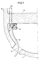
- Figure 1 is a general sectional view of the part of the device inside the water box.
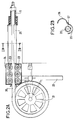
- FIG. 2A is a partial sectional view of the puller-pusher member of the control cable outside the water box
- FIG. 2B is a section through the axis IIB-IIB of FIG. 2A.
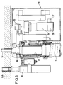
- Figure 3 is a partial sectional view of the motorized unit disposed near the tube plate.
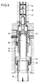
- Figure 4 is a section through the cleaning member of the interior of the tubes.
- Figures 5A, 5B, 5C are views in partial section of the temporary fixing member of a sleeve inside a tube.
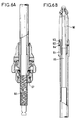
- FIGS. 6A and 6B are cross-sectional views of a roller-bearing docking rod parallel to the spindle.
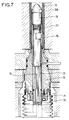
- Figure 7 is a partial section of an ultrasonic weld control lance.
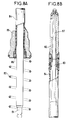
- FIGS. 8A, 8B are sectional views of a flange ensuring the final expansion of the sleeve in the tube.
- FIG. 9 is a section of a flexible tube element for introducing the tools into the water box with nestable ends.
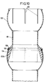
- Figure 10 is a section of a flexible tube element for introducing the tools into the water box with ends forming ball joints.
- the heat exchanger 10 ends in a water box 11 pierced with a manhole 12.
- the tubes 13 of the exchanger pass through the thick tubular plate 14.
- the internal sleeves of the tubes must be introduced into the end of the tubes up to a certain distance beyond the face of the tube plate opposite the water box.
- the various operations are carried out using a motorized unit 16, which will be shown in more detail in FIG. 3.
- the tools are brought to the motorized unit through a flexible tube 15 passing through the inspection hole.
- One leg 17 holds a ring 17A which guides the flexible tube vertically to the tube to be lined.
- the motorized unit is held in position at a given moment in front of the tube to be lined by a support member at the end of a positioning arm, not shown, and fixed to the tubular plate using members blocking in the end of other tubes, such as the member 18.
- the shooter-pusher member external to the water box, and therefore accessible without danger, is shown in Figures 2A and 2B. It is intended to pull or push a cable 20, wound on a drum 21, supported by a beam 22. Motorized rollers 23 arranged in a box 24, allow the cable to be pulled or pushed. Between these rollers and the end of the flexible tube 15 is disposed a cylindrical magazine 25 opening in two lengthwise, its cover 26 being able to pivot about an axis 27. This magazine, of outside diameter slightly less than the internal diameter of the flexible tube 15, used for the introduction of the tools which are fixed on the end of the cable 20.
- the motorized unit shown in FIG. 3 is held in position in front of the tube to be lined 15 by a carrier member, of known type, partially shown, for example a robot.
- a carrier member of known type, partially shown, for example a robot.
- a blocking member 18 in the end of an adjacent tube 14A, other locking members are not shown.
- This unit comprises two superimposed splined drive hubs, an upper hub 30 and a lower hub 33.
- the upper hub 30 is driven by the electric motor 31 by means of a belt 32.
- the lower hub 33 is driven by the pneumatic motor 34 via a belt 35. It is mounted on a bearing 36.
- a force cell 37 makes it possible to follow the value of the torque transmitted to the hub 33.
- Encoders such as 29 fix the number of spindle turns to be printed with the ddgeons or the number of turns or fraction of turns of the screw to be printed on the welding lances or the ultrasonic welding control probes, which will be discussed below.
- Infrared cells make it possible to detect the presence of tools in the motorized unit and to count the number of cage turns for the ddgeons or nut turns for the tools driven by a screw member and nut.
- the cleaning tool for the interior of the tubes is shown in FIG. 4. It comprises a rod 40, carrying a flexible brush 41, driven in rotation by the pneumatic motor via the pinion 42, and in translation by the system. with nut 43 and hollow screw 44 connected to the pneumatic motor.
- the particles detached from the internal surface of the tube by the brush are sucked by vacuum through the channels 45 and the internal bore 46 of the screw, a peripheral felt 47 protecting the thread of the screw from penetration of these particles.
- the suction of the particles continues inside the push cable 48 made of plastic, for example polyethylene, on the end of which the pinion 42 rotates by means of a ball bearing 49.
- FIGS. 5A, 5B and 5C show a balloon for temporarily fixing the sleeve inside the tube, before it comes into contact with and is welded.
- This polyurethane bladder 50 is inflatable by an internal pressure of distilled water, which can amount to 1500 bars, arriving via the conduit 51 in the cavity 52 between the bladder and the rod 53. The pressure then deforms the sleeve and temporarily fixes it against the surface of the tube to be repaired.
- An electrical contact 55 of the balloon support 54 makes it possible to signal by its closure the presence of the sleeve in the correct position for its installation.
- Part of this balloon support is flexible, in order to allow the introduction of the sleeve into the peripheral zone of the tube plate, where the wall of the water box makes access to the tubes more difficult.
- the balloon support is provided near its front end with a clamp 56 which retracts when it is pulled on it.
- the front cone 57 of this clamp facilitates the routing of the sleeve in the flexible tube and its introduction into the tube to be repaired.
- the dudgeon with parallel rollers of FIGS. 6A and 6B makes it possible to effect the coupling of the sleeve against the internal surface of the tube, inside the tube plate to ensure its fixing before welding.
- These rollers 60 have a bump which causes a very localized deformation of the sleeve, and rotate with respect to the spacer 61 of their cage by virtue of a ball bearing 62 and ball bearings 63, 64.
- the advance of the spindle 65 is ensured by screwing a threaded portion thereof 66 in a removable nut 67.
- the coupling of the sleeve in the tube beyond the plate tubular is carried out by controlled deformation of the sleeve and the tube to be repaired, with counting of the number of spindle turns of a dudgeon with inclined roller, of known type, not shown, or by controlling the volume of a balloon , also not shown, as a function of an internal pressure of water introduced by a metering pump (not shown).
- a metering pump not shown
- the welding control lance of FIG. 7 is driven in rotation by the pneumatic motor and in translation by a threaded system 70 and nut 71.
- the lance itself 72 is disposed inside the sheath 73.
- a coaxial cable 74 connected to an ultrasonic oscillator arranged in the vicinity of the push-pull device, passes through the internal bore of the hollow screw 70 and joins the ultrasonic probe 75, connected to the probe head 76 with conical end by a nut 77.
- L the interface echo between the sleeve 13A and the tube 13 is recorded for example every 100th of a turn of the probe and at each turn during its helical movement.
- the dudgeon with inclined rollers represented in FIGS. 8A and 8B is intended to ensure a final expansion of the sleeve in the tube. It comprises a spring 80 making it possible to separate the drive square 81, linked to the drive cable, from the cage 82, in order to put the rollers in the position of minimum circumscribed diameter. After placing the dudgeon in the sleeve and in the motorized drive unit, the spring is compressed by the push cable.
- the dudgeon comprises a flexible longitudinal rod 83 of thermoplastic material such as a polyamide-imide, surrounded by a sheath 84, of plastic material such as a polyamide, provided at its rear end with a stop 85 surrounding a stop nut 86.
- the stop rests on the end of the sleeve to be inserted in the tube.
- Their flexible rod 87 is extended by a steel pin 83, inside the cage 82 of hardened steel.
- the rod drive jaw is provided with grooves which allow it to be driven in rotation by the grooved hub of the pneumatic motor, and in translation by sliding in these grooves.
- the flexible tube element for example made of polyamide, represented in FIG. 9 comprises a cylindrical part 90 with an end with an internal chamfer 91, connecting via a flexible groove 93 to another end with an external chamfer 92.
- the connection of adjacent elements is effected by engaging the outer chamfer 92 of one element in the outer chamfer 91A of the other.
- the flexible tube element of FIG. 10 which can also be made of polyamide, consists of a cylindrical middle part of small thickness 101, connecting on one side to a female end 102 of spherical shape, also of small thickness, and provided with meridian slots 103, and on the other side of a male end 104, of external profile also of spherical shape, but thicker.
- the connection of two adjacent elements is facilitated by the possibility of elastic deformation of the female end 102A of an element thanks to its meridian slots during its engagement on the male end of the adjacent element.
- a plastic ring 105 is put in place and prevents the slots from opening.
- the flexible pipes formed of elements according to FIG. 9 or according to FIG. 10 have a great flexibility allowing them to join the ends of the tubes of the whole tubular plate, even those close to its periphery, from the push-pull device through the opening of the water box.
Landscapes
- Engineering & Computer Science (AREA)
- Mechanical Engineering (AREA)
- Physics & Mathematics (AREA)
- Thermal Sciences (AREA)
- General Engineering & Computer Science (AREA)
- High Energy & Nuclear Physics (AREA)
- Lining Or Joining Of Plastics Or The Like (AREA)
- Monitoring And Testing Of Nuclear Reactors (AREA)
- Investigating Or Analyzing Materials By The Use Of Ultrasonic Waves (AREA)
- Automatic Assembly (AREA)
Claims (15)
Applications Claiming Priority (2)
| Application Number | Priority Date | Filing Date | Title |
|---|---|---|---|
| FR8805448A FR2630365B1 (fr) | 1988-04-25 | 1988-04-25 | Machine de chemisage interne a distance par manchon de l'extremite de tubes d'echangeurs de chaleur |
| FR8805448 | 1988-04-25 |
Publications (2)
| Publication Number | Publication Date |
|---|---|
| EP0343368A1 EP0343368A1 (de) | 1989-11-29 |
| EP0343368B1 true EP0343368B1 (de) | 1992-03-11 |
Family
ID=9365636
Family Applications (1)
| Application Number | Title | Priority Date | Filing Date |
|---|---|---|---|
| EP89106831A Expired - Lifetime EP0343368B1 (de) | 1988-04-25 | 1989-04-17 | Im Rohrende von Wärmewechslern fernbediente Hülseneinbringvorrichtung |
Country Status (8)
| Country | Link |
|---|---|
| US (1) | US5008996A (de) |
| EP (1) | EP0343368B1 (de) |
| JP (1) | JP2718755B2 (de) |
| KR (1) | KR970002225B1 (de) |
| DE (1) | DE68900957D1 (de) |
| ES (1) | ES2030551T3 (de) |
| FR (1) | FR2630365B1 (de) |
| ZA (1) | ZA893034B (de) |
Families Citing this family (13)
| Publication number | Priority date | Publication date | Assignee | Title |
|---|---|---|---|---|
| FR2652440B1 (fr) * | 1989-09-27 | 1993-12-03 | Framatome | Procede de reparation par chemisage d'un tube tel qu'un tube de generateur de vapeur. |
| JP2580998Y2 (ja) * | 1990-09-05 | 1998-09-17 | 三菱重工業株式会社 | 蒸気発生器用プラグ取付工具 |
| US5201118A (en) * | 1992-03-09 | 1993-04-13 | Mcparland Kevin W | Process for repairing heat-exchanger tubes |
| US5557840A (en) * | 1995-02-13 | 1996-09-24 | J. E. Miller Inc. | Tube sheet locator and tube expander |
| FR2732918B1 (fr) * | 1995-04-13 | 1997-07-04 | Framatome Sa | Procede et dispositif d'introduction d'un outil en position centree a l'interieur d'une partie d'extremite d'un tube |
| CN1305440C (zh) | 1996-06-06 | 2007-03-21 | 英国电讯有限公司 | 身份识别 |
| EP0910986A1 (de) | 1997-10-24 | 1999-04-28 | BRITISH TELECOMMUNICATIONS public limited company | Bilderzeugungsapparat |
| TW463028B (en) * | 1998-04-21 | 2001-11-11 | Hitachi Shipbuilding Eng Co | Working robot for heat exchangers and operating method thereof |
| FR2809464B1 (fr) * | 2000-05-26 | 2002-10-11 | Commissariat Energie Atomique | Transmission a vis, ecrou et cable attache a la vis |
| FR2895791B1 (fr) * | 2005-12-29 | 2008-04-04 | Framatome Anp Sas | Procede de reparation d'au moins une zone de raccordement d'une plaque de partition sur une plaque tubulaire d'une boite a eau d'un echangeur de chaleur. |
| WO2008068550A1 (en) * | 2006-12-06 | 2008-06-12 | Belleli Energy Cpe S.P.A. | Method for isolating or sealing a leaky tube |
| CN115159524B (zh) * | 2022-07-06 | 2023-04-07 | 重庆朗福环保科技有限公司 | 一种二氧化碳回收液化工艺及其系统 |
| US20240329009A1 (en) * | 2023-03-29 | 2024-10-03 | Guoxing GU | Apparatus for pushing and pulling probe used for ultrasonic IRIS and eddy current testing |
Family Cites Families (12)
| Publication number | Priority date | Publication date | Assignee | Title |
|---|---|---|---|---|
| AT336926B (de) * | 1972-12-22 | 1977-06-10 | Siemens Ag | Inspektions- und reparatureinrichtung fur dampferzeuger |
| US4329769A (en) * | 1979-12-05 | 1982-05-18 | Westinghouse Electric Corp. | Apparatus for working on tubesheets |
| FR2504306A1 (fr) * | 1981-04-17 | 1982-10-22 | Framatome Sa | Dispositif de mise en place et d'extraction d'un moyen de controle ou d'un outil dans un equipement recepteur |
| US4685186A (en) * | 1982-06-28 | 1987-08-11 | Westinghouse Electric Corp. | Method of inserting a sleeve within a heat exchanger tube |
| US4571821A (en) * | 1983-08-26 | 1986-02-25 | Westinghouse Electric Corp. | Sleeve insertion |
| US4639994A (en) * | 1983-10-03 | 1987-02-03 | Westinghouse Electric Corp. | Suspension of tools for sleeving of tubes of steam generator |
| US4586250A (en) * | 1983-10-03 | 1986-05-06 | Westinghouse Electric Corp. | Apparatus for sleeving tubes in hostile environments |
| US4688327A (en) * | 1983-10-03 | 1987-08-25 | Westinghouse Electric Corp. | Sleeving of tubes of steam generator |
| US4653164A (en) * | 1984-02-14 | 1987-03-31 | Westinghouse Electric Corp. | Sleeving of tubes of steam generator in hostile environment |
| DE8509777U1 (de) * | 1985-04-01 | 1986-10-02 | Maho Werkzeugmaschinenbau Babel & Co, 8962 Pfronten | Werkzeugmaschine zur Fräs- und Drehbearbeitung |
| FR2598950A1 (fr) * | 1986-05-22 | 1987-11-27 | Thome Emmanuel | Dispositif de soudage pour intervention dans les generateurs de vapeur |
| US4829648A (en) * | 1987-01-27 | 1989-05-16 | Westinghouse Electric Corp. | Apparatus and method for simultaneously loading a reinforcing sleeve and mandrel into a tube |
-
1988
- 1988-04-25 FR FR8805448A patent/FR2630365B1/fr not_active Expired - Lifetime
-
1989
- 1989-04-17 DE DE8989106831T patent/DE68900957D1/de not_active Expired - Lifetime
- 1989-04-17 ES ES198989106831T patent/ES2030551T3/es not_active Expired - Lifetime
- 1989-04-17 EP EP89106831A patent/EP0343368B1/de not_active Expired - Lifetime
- 1989-04-21 JP JP1103328A patent/JP2718755B2/ja not_active Expired - Fee Related
- 1989-04-25 KR KR1019890005429A patent/KR970002225B1/ko not_active Expired - Fee Related
- 1989-04-25 ZA ZA893034A patent/ZA893034B/xx unknown
- 1989-04-25 US US07/342,826 patent/US5008996A/en not_active Expired - Lifetime
Also Published As
| Publication number | Publication date |
|---|---|
| JPH0217303A (ja) | 1990-01-22 |
| KR890015817A (ko) | 1989-11-25 |
| JP2718755B2 (ja) | 1998-02-25 |
| EP0343368A1 (de) | 1989-11-29 |
| ES2030551T3 (es) | 1992-11-01 |
| FR2630365B1 (fr) | 1990-07-13 |
| FR2630365A1 (fr) | 1989-10-27 |
| US5008996A (en) | 1991-04-23 |
| DE68900957D1 (de) | 1992-04-16 |
| KR970002225B1 (ko) | 1997-02-26 |
| ZA893034B (en) | 1989-12-27 |
Similar Documents
| Publication | Publication Date | Title |
|---|---|---|
| EP0343368B1 (de) | Im Rohrende von Wärmewechslern fernbediente Hülseneinbringvorrichtung | |
| EP0354090A2 (de) | Zerstörungsfreie Ultraschallvorrichtung für eine kreisförmige Schweissstelle im Inneren eines Rohres eines Dampferzeugers | |
| EP0181810B1 (de) | Verfahren und Vorrichtung zum Verdichten durch Hämmern eines in eine Rohrwand eingesetzten Dampfgeneratorrohres | |
| EP0287429B1 (de) | Herstellungsverfahren von an ihren Enden verbundenen Metallröhren | |
| CA2058225C (fr) | Dispositif de controle non destructif par ultrasons d'elements de forme allongee a section sensiblement constante | |
| EP0244283B1 (de) | Verfahren und Vorrichtung zum Ferneinbringen einer Hülse in ein Rohr des Dampferzeugers eines nuklearen Druckwasserreaktors | |
| EP0298841B1 (de) | Vorrichtung zum Schweissen in einem Rohr mit kleinem Durchmesser | |
| EP3164258B1 (de) | Vorrichtung und verfahren zur installation einer rohrförmigen verbindungsmuffe für ein rohr mit einer inneren auskleidung | |
| WO2017051118A1 (fr) | Methode d'assemblage d'un manchon tubulaire de jonction et d'un tube de chemisage de conduite par soudage laser | |
| WO2020070436A1 (fr) | Dispositif intérieur de serrage et de soudage | |
| FR2736989A1 (fr) | Dispositif destine a etre fixe de facon etanche sur au moins un element cylindrique | |
| FR2718665A1 (fr) | Outil de découpe de tuyauterie immergée par jet abrasif. | |
| FR2526532A1 (fr) | Appareil pour le controle des tubes d'un echangeur de chaleur a une distance donnee de l'extremite de ces tubes | |
| FR2718241A1 (fr) | Dispositif d'évaluation des caractéristiques lubrifiantes d'une boue de forage. | |
| EP0244282B1 (de) | Vorrichtung zum Zuführen zylindrisch geformter Teile aus der Entfernung zu einer automatischen Maschine, wie einer Maschine zum Stopfen von Rohren eines Dampfgenerators eines nuklearen Druckreaktors | |
| EP0148806B1 (de) | Verfahren zum Rohrwalzen, welches es ermöglicht, die Leistung eines Kaltpilgerschrittwalzwerkes zu erhöhen, und Vorrichtung zur Bewerkstelligung des Verfahrens | |
| EP0227535B1 (de) | Verfahren und Vorrichtung zum Herausziehen eines Rohrabschnittes aus einem Wärmetauscher | |
| CH672895A5 (de) | ||
| JPH07103953A (ja) | 管状体の超音波探傷検査装置 | |
| FR2613835A1 (fr) | Dispositif de deplacement et de mise en rotation d'un outil a l'interieur d'un tube et son utilisation pour le controle des tubes d'un generateur de vapeur | |
| FR2940156A1 (fr) | Procede de nettoyage d'impuretes a l'interieur d'une canalisation | |
| BE1011408A6 (fr) | Procede et dispositif d'usinage mecanique de la surface interne d'un tube. | |
| EP3526503B1 (de) | Vorrichtung zum halten eines verbindungsendstücks einer teilweise versenkten flexiblen unterwasserleitung | |
| FR3079297A1 (fr) | Methode de determination de la position et/ou de l'orientation d'un robot/porteur evoluant dans une tuyauterie et ensembles associes | |
| EP0292375B1 (de) | Fernsteuerungseinrichtung für die Verschiebung eines Elementes, wie ein Impulsstosswerkzeug in einem Rohr, insbesondere von einem Dampferzeuger |
Legal Events
| Date | Code | Title | Description |
|---|---|---|---|
| PUAI | Public reference made under article 153(3) epc to a published international application that has entered the european phase |
Free format text: ORIGINAL CODE: 0009012 |
|
| AK | Designated contracting states |
Kind code of ref document: A1 Designated state(s): BE CH DE ES FR GB IT LI SE |
|
| 17P | Request for examination filed |
Effective date: 19900528 |
|
| 17Q | First examination report despatched |
Effective date: 19910425 |
|
| GRAA | (expected) grant |
Free format text: ORIGINAL CODE: 0009210 |
|
| AK | Designated contracting states |
Kind code of ref document: B1 Designated state(s): BE CH DE ES FR GB IT LI SE |
|
| REF | Corresponds to: |
Ref document number: 68900957 Country of ref document: DE Date of ref document: 19920416 |
|
| GBT | Gb: translation of ep patent filed (gb section 77(6)(a)/1977) | ||
| ITF | It: translation for a ep patent filed | ||
| REG | Reference to a national code |
Ref country code: ES Ref legal event code: FG2A Ref document number: 2030551 Country of ref document: ES Kind code of ref document: T3 |
|
| PLBE | No opposition filed within time limit |
Free format text: ORIGINAL CODE: 0009261 |
|
| STAA | Information on the status of an ep patent application or granted ep patent |
Free format text: STATUS: NO OPPOSITION FILED WITHIN TIME LIMIT |
|
| 26N | No opposition filed | ||
| EAL | Se: european patent in force in sweden |
Ref document number: 89106831.4 |
|
| REG | Reference to a national code |
Ref country code: GB Ref legal event code: IF02 |
|
| PGFP | Annual fee paid to national office [announced via postgrant information from national office to epo] |
Ref country code: CH Payment date: 20030318 Year of fee payment: 15 |
|
| PGFP | Annual fee paid to national office [announced via postgrant information from national office to epo] |
Ref country code: GB Payment date: 20030326 Year of fee payment: 15 |
|
| PGFP | Annual fee paid to national office [announced via postgrant information from national office to epo] |
Ref country code: DE Payment date: 20030331 Year of fee payment: 15 |
|
| PGFP | Annual fee paid to national office [announced via postgrant information from national office to epo] |
Ref country code: SE Payment date: 20030402 Year of fee payment: 15 |
|
| PGFP | Annual fee paid to national office [announced via postgrant information from national office to epo] |
Ref country code: FR Payment date: 20030408 Year of fee payment: 15 |
|
| PGFP | Annual fee paid to national office [announced via postgrant information from national office to epo] |
Ref country code: ES Payment date: 20030416 Year of fee payment: 15 |
|
| PGFP | Annual fee paid to national office [announced via postgrant information from national office to epo] |
Ref country code: BE Payment date: 20030423 Year of fee payment: 15 |
|
| PG25 | Lapsed in a contracting state [announced via postgrant information from national office to epo] |
Ref country code: GB Free format text: LAPSE BECAUSE OF NON-PAYMENT OF DUE FEES Effective date: 20040417 |
|
| PG25 | Lapsed in a contracting state [announced via postgrant information from national office to epo] |
Ref country code: SE Free format text: LAPSE BECAUSE OF NON-PAYMENT OF DUE FEES Effective date: 20040418 |
|
| PG25 | Lapsed in a contracting state [announced via postgrant information from national office to epo] |
Ref country code: ES Free format text: LAPSE BECAUSE OF NON-PAYMENT OF DUE FEES Effective date: 20040419 |
|
| PG25 | Lapsed in a contracting state [announced via postgrant information from national office to epo] |
Ref country code: LI Free format text: LAPSE BECAUSE OF NON-PAYMENT OF DUE FEES Effective date: 20040430 Ref country code: CH Free format text: LAPSE BECAUSE OF NON-PAYMENT OF DUE FEES Effective date: 20040430 Ref country code: BE Free format text: LAPSE BECAUSE OF NON-PAYMENT OF DUE FEES Effective date: 20040430 |
|
| BERE | Be: lapsed |
Owner name: *ELECTRICITE DE FRANCE SERVICE NATIONAL Effective date: 20040430 Owner name: *STEIN INDUSTRIE Effective date: 20040430 |
|
| PG25 | Lapsed in a contracting state [announced via postgrant information from national office to epo] |
Ref country code: DE Free format text: LAPSE BECAUSE OF NON-PAYMENT OF DUE FEES Effective date: 20041103 |
|
| EUG | Se: european patent has lapsed | ||
| GBPC | Gb: european patent ceased through non-payment of renewal fee |
Effective date: 20040417 |
|
| REG | Reference to a national code |
Ref country code: CH Ref legal event code: PL |
|
| PG25 | Lapsed in a contracting state [announced via postgrant information from national office to epo] |
Ref country code: FR Free format text: LAPSE BECAUSE OF NON-PAYMENT OF DUE FEES Effective date: 20041231 |
|
| REG | Reference to a national code |
Ref country code: FR Ref legal event code: ST |
|
| PG25 | Lapsed in a contracting state [announced via postgrant information from national office to epo] |
Ref country code: IT Free format text: LAPSE BECAUSE OF NON-PAYMENT OF DUE FEES;WARNING: LAPSES OF ITALIAN PATENTS WITH EFFECTIVE DATE BEFORE 2007 MAY HAVE OCCURRED AT ANY TIME BEFORE 2007. THE CORRECT EFFECTIVE DATE MAY BE DIFFERENT FROM THE ONE RECORDED. Effective date: 20050417 |
|
| REG | Reference to a national code |
Ref country code: ES Ref legal event code: FD2A Effective date: 20040419 |