EP0343377B1 - Procédé de préparation d'une ensemble d'éléments préformés utilisables pour la réparation de voies conductrices et appareillage pour réaliser ce procédé - Google Patents
Procédé de préparation d'une ensemble d'éléments préformés utilisables pour la réparation de voies conductrices et appareillage pour réaliser ce procédé Download PDFInfo
- Publication number
- EP0343377B1 EP0343377B1 EP89107073A EP89107073A EP0343377B1 EP 0343377 B1 EP0343377 B1 EP 0343377B1 EP 89107073 A EP89107073 A EP 89107073A EP 89107073 A EP89107073 A EP 89107073A EP 0343377 B1 EP0343377 B1 EP 0343377B1
- Authority
- EP
- European Patent Office
- Prior art keywords
- metal strip
- punch
- preform
- plate
- width
- Prior art date
- Legal status (The legal status is an assumption and is not a legal conclusion. Google has not performed a legal analysis and makes no representation as to the accuracy of the status listed.)
- Expired - Lifetime
Links
Images
Classifications
-
- H—ELECTRICITY
- H05—ELECTRIC TECHNIQUES NOT OTHERWISE PROVIDED FOR
- H05K—PRINTED CIRCUITS; CASINGS OR CONSTRUCTIONAL DETAILS OF ELECTRIC APPARATUS; MANUFACTURE OF ASSEMBLAGES OF ELECTRICAL COMPONENTS
- H05K3/00—Apparatus or processes for manufacturing printed circuits
- H05K3/22—Secondary treatment of printed circuits
- H05K3/225—Correcting or repairing of printed circuits
-
- B—PERFORMING OPERATIONS; TRANSPORTING
- B21—MECHANICAL METAL-WORKING WITHOUT ESSENTIALLY REMOVING MATERIAL; PUNCHING METAL
- B21D—WORKING OR PROCESSING OF SHEET METAL OR METAL TUBES, RODS OR PROFILES WITHOUT ESSENTIALLY REMOVING MATERIAL; PUNCHING METAL
- B21D28/00—Shaping by press-cutting; Perforating
- B21D28/02—Punching blanks or articles with or without obtaining scrap; Notching
- B21D28/06—Making more than one part out of the same blank; Scrapless working
-
- H—ELECTRICITY
- H05—ELECTRIC TECHNIQUES NOT OTHERWISE PROVIDED FOR
- H05K—PRINTED CIRCUITS; CASINGS OR CONSTRUCTIONAL DETAILS OF ELECTRIC APPARATUS; MANUFACTURE OF ASSEMBLAGES OF ELECTRICAL COMPONENTS
- H05K2201/00—Indexing scheme relating to printed circuits covered by H05K1/00
- H05K2201/10—Details of components or other objects attached to or integrated in a printed circuit board
- H05K2201/10227—Other objects, e.g. metallic pieces
- H05K2201/1028—Thin metal strips as connectors or conductors
-
- H—ELECTRICITY
- H05—ELECTRIC TECHNIQUES NOT OTHERWISE PROVIDED FOR
- H05K—PRINTED CIRCUITS; CASINGS OR CONSTRUCTIONAL DETAILS OF ELECTRIC APPARATUS; MANUFACTURE OF ASSEMBLAGES OF ELECTRICAL COMPONENTS
- H05K2201/00—Indexing scheme relating to printed circuits covered by H05K1/00
- H05K2201/10—Details of components or other objects attached to or integrated in a printed circuit board
- H05K2201/10613—Details of electrical connections of non-printed components, e.g. special leads
- H05K2201/10742—Details of leads
- H05K2201/10886—Other details
- H05K2201/10924—Leads formed from a punched metal foil
-
- H—ELECTRICITY
- H05—ELECTRIC TECHNIQUES NOT OTHERWISE PROVIDED FOR
- H05K—PRINTED CIRCUITS; CASINGS OR CONSTRUCTIONAL DETAILS OF ELECTRIC APPARATUS; MANUFACTURE OF ASSEMBLAGES OF ELECTRICAL COMPONENTS
- H05K2203/00—Indexing scheme relating to apparatus or processes for manufacturing printed circuits covered by H05K3/00
- H05K2203/17—Post-manufacturing processes
- H05K2203/173—Adding connections between adjacent pads or conductors, e.g. for modifying or repairing
-
- H—ELECTRICITY
- H05—ELECTRIC TECHNIQUES NOT OTHERWISE PROVIDED FOR
- H05K—PRINTED CIRCUITS; CASINGS OR CONSTRUCTIONAL DETAILS OF ELECTRIC APPARATUS; MANUFACTURE OF ASSEMBLAGES OF ELECTRICAL COMPONENTS
- H05K3/00—Apparatus or processes for manufacturing printed circuits
- H05K3/30—Assembling printed circuits with electric components, e.g. with resistors
- H05K3/32—Assembling printed circuits with electric components, e.g. with resistors electrically connecting electric components or wires to printed circuits
- H05K3/34—Assembling printed circuits with electric components, e.g. with resistors electrically connecting electric components or wires to printed circuits by soldering
- H05K3/3465—Application of solder
-
- Y—GENERAL TAGGING OF NEW TECHNOLOGICAL DEVELOPMENTS; GENERAL TAGGING OF CROSS-SECTIONAL TECHNOLOGIES SPANNING OVER SEVERAL SECTIONS OF THE IPC; TECHNICAL SUBJECTS COVERED BY FORMER USPC CROSS-REFERENCE ART COLLECTIONS [XRACs] AND DIGESTS
- Y10—TECHNICAL SUBJECTS COVERED BY FORMER USPC
- Y10T—TECHNICAL SUBJECTS COVERED BY FORMER US CLASSIFICATION
- Y10T83/00—Cutting
- Y10T83/04—Processes
- Y10T83/0524—Plural cutting steps
- Y10T83/0577—Repetitive blanking
-
- Y—GENERAL TAGGING OF NEW TECHNOLOGICAL DEVELOPMENTS; GENERAL TAGGING OF CROSS-SECTIONAL TECHNOLOGIES SPANNING OVER SEVERAL SECTIONS OF THE IPC; TECHNICAL SUBJECTS COVERED BY FORMER USPC CROSS-REFERENCE ART COLLECTIONS [XRACs] AND DIGESTS
- Y10—TECHNICAL SUBJECTS COVERED BY FORMER USPC
- Y10T—TECHNICAL SUBJECTS COVERED BY FORMER US CLASSIFICATION
- Y10T83/00—Cutting
- Y10T83/04—Processes
- Y10T83/06—Blanking
-
- Y—GENERAL TAGGING OF NEW TECHNOLOGICAL DEVELOPMENTS; GENERAL TAGGING OF CROSS-SECTIONAL TECHNOLOGIES SPANNING OVER SEVERAL SECTIONS OF THE IPC; TECHNICAL SUBJECTS COVERED BY FORMER USPC CROSS-REFERENCE ART COLLECTIONS [XRACs] AND DIGESTS
- Y10—TECHNICAL SUBJECTS COVERED BY FORMER USPC
- Y10T—TECHNICAL SUBJECTS COVERED BY FORMER US CLASSIFICATION
- Y10T83/00—Cutting
- Y10T83/202—With product handling means
- Y10T83/2092—Means to move, guide, or permit free fall or flight of product
- Y10T83/2096—Means to move product out of contact with tool
- Y10T83/2135—Moving stripper timed with tool stroke
- Y10T83/215—Carried by moving tool element or its support
- Y10T83/2155—Stripper biased against product
- Y10T83/2159—By spring means
-
- Y—GENERAL TAGGING OF NEW TECHNOLOGICAL DEVELOPMENTS; GENERAL TAGGING OF CROSS-SECTIONAL TECHNOLOGIES SPANNING OVER SEVERAL SECTIONS OF THE IPC; TECHNICAL SUBJECTS COVERED BY FORMER USPC CROSS-REFERENCE ART COLLECTIONS [XRACs] AND DIGESTS
- Y10—TECHNICAL SUBJECTS COVERED BY FORMER USPC
- Y10T—TECHNICAL SUBJECTS COVERED BY FORMER US CLASSIFICATION
- Y10T83/00—Cutting
- Y10T83/444—Tool engages work during dwell of intermittent workfeed
- Y10T83/4453—Work moved solely by movable abutment
-
- Y—GENERAL TAGGING OF NEW TECHNOLOGICAL DEVELOPMENTS; GENERAL TAGGING OF CROSS-SECTIONAL TECHNOLOGIES SPANNING OVER SEVERAL SECTIONS OF THE IPC; TECHNICAL SUBJECTS COVERED BY FORMER USPC CROSS-REFERENCE ART COLLECTIONS [XRACs] AND DIGESTS
- Y10—TECHNICAL SUBJECTS COVERED BY FORMER USPC
- Y10T—TECHNICAL SUBJECTS COVERED BY FORMER US CLASSIFICATION
- Y10T83/00—Cutting
- Y10T83/444—Tool engages work during dwell of intermittent workfeed
- Y10T83/4534—Unequal work feed increments in recurring series
-
- Y—GENERAL TAGGING OF NEW TECHNOLOGICAL DEVELOPMENTS; GENERAL TAGGING OF CROSS-SECTIONAL TECHNOLOGIES SPANNING OVER SEVERAL SECTIONS OF THE IPC; TECHNICAL SUBJECTS COVERED BY FORMER USPC CROSS-REFERENCE ART COLLECTIONS [XRACs] AND DIGESTS
- Y10—TECHNICAL SUBJECTS COVERED BY FORMER USPC
- Y10T—TECHNICAL SUBJECTS COVERED BY FORMER US CLASSIFICATION
- Y10T83/00—Cutting
- Y10T83/444—Tool engages work during dwell of intermittent workfeed
- Y10T83/463—Work-feed element contacts and moves with work
- Y10T83/4635—Comprises element entering aperture in, or engaging abutment surface on, work
Definitions
- the invention relates to a process for the production of molded parts with at least one molded part for repairing conductor tracks, in particular for repairing meandering, trapezoidal conductor tracks using hard-soldered molded parts, the width of which is in the range of, for example, 50 to 70 ⁇ m. Molded parts of this size usually have a total thickness of approx. 20 to 30 ⁇ m.
- the repair of conductor tracks is carried out by means of molded parts that are congruent to interrupt the conductor track.
- molded parts are produced, which contain a large number of molded parts with all possible configurations of a conductor track.
- Such a molded part is selected for its congruence and punched out symmetrically to the interruption from the molded part.
- the subsequent repair is carried out in another independent process.
- DE-PS 22 51 997 describes a method which relates essentially to the material properties of a fine strip and its coating with all parameters of brazing for repairing the conductor track.
- the conductor tracks considered here have a width of 100 to 150 ⁇ m and a height of approximately 50 ⁇ m.
- the main difference to the generation of conductor tracks that can be handled today is the halving of the conductor track width and the design in the form of meandering structures.
- Previously known stamping methods which are based on the positive stamping principle, that is to say whose stamps have the same width and contour of the molded part to be punched out, trigger with the dimensioning described, in which a stamp should have a width of, for example, 60 ⁇ m their limits. Such punches are not up to the stresses when punching copper strips or hard-soldered copper strips and break.
- the invention is based on the object of producing a method for producing a molded part with a large number of molded parts, the molded part being said to have good stability for further handling.
- the mounting plate can also be swiveled out and in about an appropriately vertical axis of rotation.
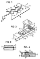
- FIG. 1 shows a section of a molded part 1 which is produced by means of the method according to the invention and the corresponding device.
- This contains a part of the all-round stable frame, which has positioning holes 9 and surrounds a plurality of molded parts 2.
- the parts punched out during the stamping process leave areas corresponding to the stamp width D, between which the remaining webs appear as molded parts 2.
- These molded parts have, for example, the dimensions of: width B approx. 60 ⁇ m, height H approx. 25 ⁇ m and length L of a conductor track configuration of 1.5 mm.
- the length of the conductor track configuration represents a periodic image return, with different conductor track configurations being able to appear within an overall length of a molded part.
- a connection for a connecting eye 16 is indicated, which is expediently placed at the transition from a residual web to the surrounding frame.
- the molded parts 2 With the negative punching method, which takes out parts corresponding to the punch width D and leaves the remaining webs, the molded parts 2, repair parts with a width of the required 50 to 70 ⁇ m can be produced.
- the total punching length of the molded parts is designed for 6.4 mm and depends on the periodic return of the conductor track configurations.
- the cutting air for a burr-free cut with a 20 ⁇ m thick copper foil is between 0 and 2 ⁇ m.
- the stability of a molded part benefit is given on the one hand by the surrounding frame and is additionally reinforced by one or more wide remaining webs. Such remaining webs are realized, for example, usually by three empty cycles after 34 working cycles.
- FIG. 2 shows an apparatus for performing the method according to the invention.
- a metal strip 14 is placed on a mounting plate 17 of the carriage 11, which is driven and clocked by means of a motor 4, and locked by positioning pins 8 which engage in positioning holes 9.
- the direction of advance of the carriage 11 with the metal band 14 is indicated by large arrows.
- the Stroke movements of the punch 3 are also indicated by a double arrow.
- the punch 3 interacts with a cutting plate 10.
- the hold-down device additionally required for the punching process for clamping the remaining web is not shown.
- the already described matching of punch width D and feed V produces the molded parts 2 with the corresponding width B in the form of residual webs.
- FIG. 2 clearly shows the circumferential frame of the molded part 1 which arises from the fact that the length of the punch 3 is smaller than the entire width of the metal strip 14.
- FIG. 3 shows in section a conductor track 7, via which a corresponding molded part 2 is shown for repair.
- the molded part 2 consists of a carrier, the metal strip 5, and a hard solder plating 6.
- the burrs produced on both sides by the stamping are indicated in FIG. 3.
- the length of such a molded part 2 and its selection within various configurations in a residual web are selected with regard to further processing such that a molded part 2 separated from a molded part benefit is congruent with the conductor path configuration and as symmetrical as possible, overlapping on both sides for the conductor path interruption for the connection process.
- FIG. 4 shows an advantageous embodiment of the device shown in FIG. 2 for carrying out the method according to the invention.
- the errors in the locking of a metal strip 14, which are always present due to tolerances between the positioning holes 9 and the positioning pins 8, can be avoided by simultaneously using an auxiliary plate 12 and a clamping plate 13.
- the insertion and locking of the metal strip 14 on the slide 11 is done in such a way that the auxiliary plate 12, a type of support plate, is first attached to the corresponding shape of the slide 11.
- the holder is done by one or more permanent months housed in the carriage 11 and the corresponding magnetic design of the auxiliary plate 12.
- the metal strip 14 is then placed in the positioning pins 8 present on the slide 11.
- the clamping plate 13 is placed and hung on the pin, the auxiliary plate 12 can be removed downwards.
- the clamping plate 13 is also held by said permanent magnets accommodated in the carriage 11.
- the receiving plate 17 on the carriage 11 so as to be pivotable about an axis of rotation.
- This axis of rotation is perpendicular and is expediently placed outside the contact surface of the metal strip 14, as is indicated in FIG. 2.
- the motor 4 is designed as a stepper motor.
- the steps with the feed V are specified via a stepper motor control.
Landscapes
- Engineering & Computer Science (AREA)
- Manufacturing & Machinery (AREA)
- Microelectronics & Electronic Packaging (AREA)
- Mechanical Engineering (AREA)
- Manufacture Of Motors, Generators (AREA)
- Punching Or Piercing (AREA)
- Manufacturing Of Printed Wiring (AREA)
Claims (7)
Priority Applications (1)
| Application Number | Priority Date | Filing Date | Title |
|---|---|---|---|
| AT89107073T ATE62097T1 (de) | 1988-05-26 | 1989-04-19 | Verfahren zur herstellung von formteilnutzen mit formteilen zur reparatur von leiterbahnen und vorrichtung zur durchfuehrung des verfahrens. |
Applications Claiming Priority (2)
| Application Number | Priority Date | Filing Date | Title |
|---|---|---|---|
| DE3817901 | 1988-05-26 | ||
| DE3817901 | 1988-05-26 |
Publications (2)
| Publication Number | Publication Date |
|---|---|
| EP0343377A1 EP0343377A1 (fr) | 1989-11-29 |
| EP0343377B1 true EP0343377B1 (fr) | 1991-03-27 |
Family
ID=6355168
Family Applications (1)
| Application Number | Title | Priority Date | Filing Date |
|---|---|---|---|
| EP89107073A Expired - Lifetime EP0343377B1 (fr) | 1988-05-26 | 1989-04-19 | Procédé de préparation d'une ensemble d'éléments préformés utilisables pour la réparation de voies conductrices et appareillage pour réaliser ce procédé |
Country Status (4)
| Country | Link |
|---|---|
| US (1) | US5005455A (fr) |
| EP (1) | EP0343377B1 (fr) |
| AT (1) | ATE62097T1 (fr) |
| DE (1) | DE58900071D1 (fr) |
Family Cites Families (20)
| Publication number | Priority date | Publication date | Assignee | Title |
|---|---|---|---|---|
| US776511A (en) * | 1902-06-12 | 1904-12-06 | Gen Electric | Mechanism for punching sheet metal. |
| US2378603A (en) * | 1943-05-12 | 1945-06-19 | George F Wales | Punching apparatus |
| US2410372A (en) * | 1944-12-18 | 1946-10-29 | George F Wales | Method of and apparatus for punching by transfer means |
| US3254550A (en) * | 1964-07-21 | 1966-06-07 | Mcdonald Tool & Die Co Inc | Die apparatus |
| US3252365A (en) * | 1964-10-23 | 1966-05-24 | Compo Shoe Machinery Corp | Cutting machine with auxiliary die |
| US3599520A (en) * | 1969-10-29 | 1971-08-17 | Mead Corp | Method of diecutting a blank |
| US3715943A (en) * | 1971-06-02 | 1973-02-13 | Arnold Eng Co | Method of stamping laminations |
| US3848495A (en) * | 1972-03-28 | 1974-11-19 | Doric Corp | Die fixture |
| DE2251997C3 (de) * | 1972-10-24 | 1985-03-14 | Siemens AG, 1000 Berlin und 8000 München | Verfahren zur Reparatur von schmalen Leiterbahnen elektrischer Schaltungsplatten |
| US3908980A (en) * | 1973-08-02 | 1975-09-30 | Alexander Fowler | Work loading, unloading, and positioning means for handling sheet material in power presses and the like |
| ZA741915B (en) * | 1974-03-25 | 1975-05-28 | A Mentis | Improvements in or relating to metal punching machines |
| JPS52111080A (en) * | 1976-03-15 | 1977-09-17 | Kazutoshi Yamazaki | Method of obtaining blanks from material of specified length |
| FR2384562A1 (fr) * | 1976-09-15 | 1978-10-20 | Aerosol Inventions Dev | Procede de decoupe des pieces avant emboutissage sur outil a suivre |
| DE3025875A1 (de) * | 1980-07-08 | 1982-02-04 | Siemens AG, 1000 Berlin und 8000 München | Vorrichtung zur reparatur von leiterbahnunterbrechungen |
| US4519284A (en) * | 1982-07-26 | 1985-05-28 | The Warner & Swasey Company | Universal sheet metal holder |
| US4697485A (en) * | 1986-04-16 | 1987-10-06 | Preco Industries, Inc. | Die press having 3-axis registration system operable during material advancement |
| JPH033549Y2 (fr) * | 1986-07-16 | 1991-01-30 | ||
| JPS6343730A (ja) * | 1986-08-09 | 1988-02-24 | Murata Mach Ltd | 打抜き加工方法および打抜き加工装置 |
| US4817477A (en) * | 1986-12-19 | 1989-04-04 | C.A. Picard, Inc. | Apparatus and method of automatically punching hole patterns in sheets of material |
| US4808157A (en) * | 1987-07-13 | 1989-02-28 | Neuro Delivery Technology, Inc. | Multi-lumen epidural-spinal needle |
-
1989
- 1989-03-23 US US07/327,909 patent/US5005455A/en not_active Expired - Fee Related
- 1989-04-19 DE DE8989107073T patent/DE58900071D1/de not_active Expired - Lifetime
- 1989-04-19 AT AT89107073T patent/ATE62097T1/de not_active IP Right Cessation
- 1989-04-19 EP EP89107073A patent/EP0343377B1/fr not_active Expired - Lifetime
Also Published As
| Publication number | Publication date |
|---|---|
| DE58900071D1 (de) | 1991-05-02 |
| EP0343377A1 (fr) | 1989-11-29 |
| ATE62097T1 (de) | 1991-04-15 |
| US5005455A (en) | 1991-04-09 |
Similar Documents
| Publication | Publication Date | Title |
|---|---|---|
| DE2356140C2 (de) | Vorrichtung zur Befestigung von wenigstens einem zuvor auf einem dünnen Plastikfilm montierten integrierten Schaltungsplättchen | |
| EP0343661A2 (fr) | Procédé et dispositif de fabrication de pièces poinçonnées soudées | |
| EP0284902A2 (fr) | Procédé et dispositif pour joindre des tôles minces mises les unes sur les autres | |
| DE4244544A1 (en) | Lead frame blanking appts. for integrated circuit mfr. - has press tool with individual punches set into die block for formation of connection leads for IC elements | |
| DE3025875A1 (de) | Vorrichtung zur reparatur von leiterbahnunterbrechungen | |
| DE2727445C2 (de) | Verfahren und Vorrichtung zum Ausschneiden und/oder Lochen von Werkstücken aus metallischen Flachwerkstoffen | |
| DE2625915B2 (de) | Verfahren zur Herstellung von elektrischen Kontakten | |
| DE1171547B (de) | Verfahren zur Herstellung von mit Edelmetall-Kontakten ausgestatteten Kontaktfedern | |
| DE2509107A1 (de) | Verfahren zur herstellung eines kommutators | |
| EP0162508B1 (fr) | Procédé et dispositif pour la fabrication de condensateurs céramiques à couches multiples | |
| EP1449415B1 (fr) | Procede et dispositif de metallisation de substrats et plaquettes | |
| DE2555697A1 (de) | Verfahren zur herstellung von doppelkontaktnieten | |
| EP0343377B1 (fr) | Procédé de préparation d'une ensemble d'éléments préformés utilisables pour la réparation de voies conductrices et appareillage pour réaliser ce procédé | |
| EP0520295B1 (fr) | Procédé et dispositif pour former des conduites extérieures avec des éléments constitutifs montables à la surface | |
| DE1937818A1 (de) | Verfahren und Vorrichtung zum Ausstanzen sechseckiger Rohlinge | |
| DE102007047836A1 (de) | Verfahren zum Herstellen einer gratfreien Schnittfläche und Vorrichtung zur Durchführung des Verfahrens | |
| DE1590564A1 (de) | Verfahren und Vorrichtung zur Herstellung gedruckter Schaltungsplatten | |
| DE3738164A1 (de) | Vorrichtung zur bearbeitung und bereitstellung von tapepaks fuer bestueckautomaten | |
| DE3016168C2 (de) | Gesamtverbundschneid- und Biegewerkzeug | |
| DE3323359C2 (de) | Verfahren zum Herstellen von Schmiedeteilen mit Hilfskörpern zur automatisierten Handhabung der Schmiedeteile | |
| DE1944296C3 (de) | Verfahren zum Fertigen von zwei konzentrischen Werkstücken durch Ausstanzen aus bandförmigem Werkstoff | |
| WO1990005378A1 (fr) | Procede de fabrication de boitiers pour circuits hybrides | |
| DE10340794B4 (de) | Folgewerkzeug zum Herstellen eines komplex geformten und mit Öffnungen in verschiedenen Ebenen versehenen Bauteils | |
| DE4003918C1 (en) | Mfg. stamping or punch part from metal strip - shearing edges into slots and simultaneously lifting both sides to heap-up material | |
| DE2736625A1 (de) | Verfahren zur herstellung eines meisseltyp-saegekettengliedes |
Legal Events
| Date | Code | Title | Description |
|---|---|---|---|
| PUAI | Public reference made under article 153(3) epc to a published international application that has entered the european phase |
Free format text: ORIGINAL CODE: 0009012 |
|
| AK | Designated contracting states |
Kind code of ref document: A1 Designated state(s): AT BE CH DE FR GB IT LI NL |
|
| 17P | Request for examination filed |
Effective date: 19900110 |
|
| 17Q | First examination report despatched |
Effective date: 19900914 |
|
| GRAA | (expected) grant |
Free format text: ORIGINAL CODE: 0009210 |
|
| AK | Designated contracting states |
Kind code of ref document: B1 Designated state(s): AT BE CH DE FR GB IT LI NL |
|
| REF | Corresponds to: |
Ref document number: 62097 Country of ref document: AT Date of ref document: 19910415 Kind code of ref document: T |
|
| REF | Corresponds to: |
Ref document number: 58900071 Country of ref document: DE Date of ref document: 19910502 |
|
| ET | Fr: translation filed | ||
| ITF | It: translation for a ep patent filed | ||
| GBT | Gb: translation of ep patent filed (gb section 77(6)(a)/1977) | ||
| PGFP | Annual fee paid to national office [announced via postgrant information from national office to epo] |
Ref country code: CH Payment date: 19910724 Year of fee payment: 3 |
|
| PLBE | No opposition filed within time limit |
Free format text: ORIGINAL CODE: 0009261 |
|
| STAA | Information on the status of an ep patent application or granted ep patent |
Free format text: STATUS: NO OPPOSITION FILED WITHIN TIME LIMIT |
|
| 26N | No opposition filed | ||
| PGFP | Annual fee paid to national office [announced via postgrant information from national office to epo] |
Ref country code: AT Payment date: 19920327 Year of fee payment: 4 |
|
| PGFP | Annual fee paid to national office [announced via postgrant information from national office to epo] |
Ref country code: FR Payment date: 19920428 Year of fee payment: 4 Ref country code: BE Payment date: 19920428 Year of fee payment: 4 |
|
| PG25 | Lapsed in a contracting state [announced via postgrant information from national office to epo] |
Ref country code: LI Effective date: 19920430 Ref country code: CH Effective date: 19920430 |
|
| PGFP | Annual fee paid to national office [announced via postgrant information from national office to epo] |
Ref country code: NL Payment date: 19920430 Year of fee payment: 4 |
|
| REG | Reference to a national code |
Ref country code: CH Ref legal event code: PL |
|
| PG25 | Lapsed in a contracting state [announced via postgrant information from national office to epo] |
Ref country code: GB Effective date: 19930419 Ref country code: AT Effective date: 19930419 |
|
| PG25 | Lapsed in a contracting state [announced via postgrant information from national office to epo] |
Ref country code: BE Effective date: 19930430 |
|
| BERE | Be: lapsed |
Owner name: SIEMENS A.G. Effective date: 19930430 |
|
| PG25 | Lapsed in a contracting state [announced via postgrant information from national office to epo] |
Ref country code: NL Effective date: 19931101 |
|
| GBPC | Gb: european patent ceased through non-payment of renewal fee |
Effective date: 19930419 |
|
| NLV4 | Nl: lapsed or anulled due to non-payment of the annual fee | ||
| PG25 | Lapsed in a contracting state [announced via postgrant information from national office to epo] |
Ref country code: FR Effective date: 19931229 |
|
| REG | Reference to a national code |
Ref country code: FR Ref legal event code: ST |
|
| PGFP | Annual fee paid to national office [announced via postgrant information from national office to epo] |
Ref country code: DE Payment date: 19960620 Year of fee payment: 8 |
|
| PG25 | Lapsed in a contracting state [announced via postgrant information from national office to epo] |
Ref country code: DE Free format text: LAPSE BECAUSE OF NON-PAYMENT OF DUE FEES Effective date: 19980101 |
|
| PG25 | Lapsed in a contracting state [announced via postgrant information from national office to epo] |
Ref country code: IT Free format text: LAPSE BECAUSE OF NON-PAYMENT OF DUE FEES Effective date: 20050419 |