EP0343391A2 - Valve pilote pour élément de ressort de véhicule - Google Patents
Valve pilote pour élément de ressort de véhicule Download PDFInfo
- Publication number
- EP0343391A2 EP0343391A2 EP19890107537 EP89107537A EP0343391A2 EP 0343391 A2 EP0343391 A2 EP 0343391A2 EP 19890107537 EP19890107537 EP 19890107537 EP 89107537 A EP89107537 A EP 89107537A EP 0343391 A2 EP0343391 A2 EP 0343391A2
- Authority
- EP
- European Patent Office
- Prior art keywords
- spring element
- switching valve
- pressure
- line
- control device
- Prior art date
- Legal status (The legal status is an assumption and is not a legal conclusion. Google has not performed a legal analysis and makes no representation as to the accuracy of the status listed.)
- Withdrawn
Links
Images


Classifications
-
- B—PERFORMING OPERATIONS; TRANSPORTING
- B60—VEHICLES IN GENERAL
- B60G—VEHICLE SUSPENSION ARRANGEMENTS
- B60G17/00—Resilient suspensions having means for adjusting the spring or vibration-damper characteristics, for regulating the distance between a supporting surface and a sprung part of vehicle or for locking suspension during use to meet varying vehicular or surface conditions, e.g. due to speed or load
- B60G17/02—Spring characteristics, e.g. mechanical springs and mechanical adjusting means
- B60G17/04—Spring characteristics, e.g. mechanical springs and mechanical adjusting means fluid spring characteristics
- B60G17/052—Pneumatic spring characteristics
-
- B—PERFORMING OPERATIONS; TRANSPORTING
- B60—VEHICLES IN GENERAL
- B60G—VEHICLE SUSPENSION ARRANGEMENTS
- B60G2202/00—Indexing codes relating to the type of spring, damper or actuator
- B60G2202/10—Type of spring
- B60G2202/15—Fluid spring
- B60G2202/152—Pneumatic spring
-
- B—PERFORMING OPERATIONS; TRANSPORTING
- B60—VEHICLES IN GENERAL
- B60G—VEHICLE SUSPENSION ARRANGEMENTS
- B60G2500/00—Indexing codes relating to the regulated action or device
- B60G2500/20—Spring action or springs
- B60G2500/204—Pressure regulating valves for air-springs
-
- B—PERFORMING OPERATIONS; TRANSPORTING
- B60—VEHICLES IN GENERAL
- B60G—VEHICLE SUSPENSION ARRANGEMENTS
- B60G2500/00—Indexing codes relating to the regulated action or device
- B60G2500/20—Spring action or springs
- B60G2500/22—Spring constant
Definitions
- the invention relates to a switching valve for a vehicle spring element according to the preamble of the main claim.
- a vehicle spring element is already known in which an additional volume can be switched on and off in order to adjust the spring characteristic to the volume of the spring element.
- relatively large flow cross sections must be selected, and this requires a relatively large actuating device.
- the switching valve according to the invention with the characterizing features of the main claim has the advantage that the pressure medium can be brought into effect by arranging a pilot control device such that the closing bodies located in the channels release or shut off the connection between the volume of the spring element and the additional volume.
- a relatively large flow cross section is available.
- a pilot control device with which a small portion of the pressure medium flowing through is directed onto the partition / partitions, this in turn can indirectly or directly influence the closing body in the sense of a valve closure.
- This makes it possible to control a relatively large volume with a relatively small pilot control device. Only small forces are required to actuate the pilot control device. This makes it possible to use e.g. to operate a relatively small magnet.
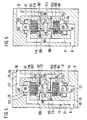
- a vehicle spring element is provided with the reference number 1.
- the spring element 1 is connected to the switching valve 5 via a line 2.
- the line 2 is connected to the switching valve 5 at a first line connection 6.
- a further line connection 10 is located on the switching valve 5, where an additional volume 11 is connected to the switching valve 5 via a line 14.
- Further components, for example further additional volumes, can be connected to one or more branches 15 in line 14.
- the branches 9 and 15 can also, as not shown, be integrated directly into the switching valve 5.
- connection 17 between the two line connections 6 and 10 within the switching valve 5.
- a duct section 18 initially leads to a branch 19.
- the connection 17 branches into a first duct 21 and a second duct 22 until it unites again in a branch 25, in order then to continue in the duct section 26 up to the second line connection 10.
- a first closing body 29 is arranged in the first channel 21 and a second closing body 30 is arranged in the second channel 22.
- the connection 17 is divided into a first pressure region 31 and a second pressure region 32 by the two closing bodies 29 and 30.
- the first pressure area 31 extends as a cavity between the first line connection 6, the first closing body 29 and the second closing body 30.
- the second pressure area 32 is delimited by the closing bodies 29 and 30 and by the second line connection 10.
- the first Closing body 29 is connected via a first semi-loose coupling 33 and the second closing body 30 via a second semi-loose coupling 34 to a movable partition 35.
- the movable partition 35 is designed in the form of a membrane 38 stiffened by two plates 39 and 40.
- the two semi-loose couplings 33 and 34 essentially consist of two parts, a clamp part 43 and 44 and a pin part 45 and 46.
- the pin part 45 is free relative to the clamp part 43 and the pin part 46 with respect to the clamp part 44 movable.
- the pin head 47 which can come into contact with the shoulder 48, limits the maximum distance of the closing body 29 from the movable partition 35.
- the pin part 45 with the pin head 47 can dip into a cavity 51 of the clamp part 43, so that the closing body 29 can come to rest against a housing-fixed valve seat 54 in the channel 21, regardless of the position of the movable partition 35.
- the second clutch 34 with the closing body 30 and a cavity 52 in the clamp part 44 is designed in the same way as the first clutch 33 with the closing body 29. The second closing body 30 can be brought into contact with a valve seat 55 fixed to the housing.
- the movable partition 35 separates a space 56 into a first chamber 57 and a second chamber 58.
- the first chamber 57 is connected to the first pressure region 31 via a first passage 61.
- chamber 58 which is connected to second pressure region 32 via a second passage 62.
- the passages 61 and 62 can be so narrow that the pressure medium flowing through is more or less throttled.
- the first chamber 57 is connected to the second chamber 58 via a line 66.
- a pilot control device 67 is located in line 66. Line 66 can be closed and opened with pilot control device 67. Depending on the design of the pilot control device 67, intermediate positions between open and closed are also possible.
- the before Control device 67 was shown symbolically in FIG. 1 as a 2/2-way valve.
- the symbol for the directional control valve shows two switching positions, a first switching position 69 and a second switching position 70. If the pilot control device 67 is in the first switching position 69, as shown symbolically in FIG. 1, then the first chamber 57 with the second chamber 58 connected and there is pressure equalization between these two chambers. The pressure medium creates no pressure on the movable partition and this can move more or less freely within the space 56.
- One or more springs can be located in chamber 57 and / or in chamber 58. This leads to a possibly necessary centering of the movable partition 35.
- a first spring 74 is located between the first closing body 29 and a first system 71 in the first channel 21, and a second spring 75 is located between the second closing body 30 and a second system 72 in the second channel 22.
- the two springs 74 and 75 are arranged so that a spring force can act in the closing direction on both closing bodies 29 and 30.
- the pilot control device 67 is in the switch position 69, in which the pressure medium between the first chamber 57 and the second chamber 58 can compensate. If the pilot control device 67 is in this switching position, the movable partition 35 cannot exert any force on the closing bodies 29 and 30 via the couplings 33 and 34. The closing bodies 29 and 30 can be closed and opened by the pressure medium, depending on which side of the closing body the higher pressure prevails. If the pressure in the spring element 1 is higher than the pressure in the additional volume 11, for example when the spring element 1 is deflected, then the pressure medium flows from the spring element 1 through the line 2 via the line connection 6 into the switching valve 5.
- the first pressure range 31 to a pressure increase and causes the closing body 30 in the channel 22 to be pressed against the valve seat 55.
- the closing movement of the closing body 30 is supported by the spring 75.
- the pressure increase in the first pressure region 31 also causes the closing body 29 to lift off the valve seat 54 counter to the spring force exerted by the spring 74.
- the pressure medium can flow from the spring element 1 via the first line connection 6, through the first channel 21, via the second line connection 10 to the additional volume 11.
- the pressure in the spring element 1 is reduced, for example when the spring element springs out, the pressure in the second pressure region 32 is higher than in the first pressure region 31.
- the length of the pin part 45, the pin part 46, the cavity 51 and the cavity 52 must be such that when the closing body 30 comes into contact with the valve seat 55, that then the closing body 29 can lift sufficiently far from the valve seat 54; Likewise, when the closing body 29 bears against the valve seat 54, the closing body 30 must be able to lift off the valve seat 55 sufficiently far.
- the pressure in chamber 57 is also higher than in chamber 58, since no pressure equalization can take place between these two chambers 57 and 58 because of the switching position 70 of pilot control device 67.
- the higher pressure in the chamber 57 compared to the pressure in the chamber 58 leads to a deflection of the movable partition 35 in a direction closing the first channel 21.
- the pressure difference between the pressure areas 31 and 32 presses on the active surface 81 of the closing body 29 and tries to open the channel 21.
- the same pressure difference also acts on an active surface 83 of the movable partition 35. The two forces on the active surface 81 and on the active surface 83 are directed in opposite directions.
- the first and the second coupling 33 and 34 are also passed through the passages 61 and 62. This is not absolutely necessary, but a narrow clearance can also be provided for passing the couplings through and the passages 61 and 62 can be separate bores.
- FIG. 3 as a second exemplary embodiment, essentially the same switching valve 5 is shown as in FIGS. 1 and 2.
- the passages 61 and 62 can also be blocked and opened by the pilot control device 67.
- the pilot control device 67 is modified somewhat from the pilot control device 67 described in the first exemplary embodiment, and the passages 61 and 62 are guided through the pilot control device 67.
- the first switching position 69 of the pilot control device 67 the first chamber 57 has a connection to the second chamber 58 via the pilot control device 67 and the line 66.
- the first chamber 57 is separated from the second chamber 58 in the second switching position 70 of the pilot control device 67.
- the first pressure region 31 is connected to the first chamber 57 via the passage 61 guided through the pilot control device 67 and the second pressure region 32 is connected to the second chamber 58 via the passage 62 guided through the pilot control device 67.
- the passages 61 and 62 between the first pressure region 31 and the first chamber 57 and between the second pressure region 32 and the second chamber 58 are blocked. This makes it possible to ensure perfect pressure equalization between the chambers 57 and 58 even with a small cross section of the line 66 and with a small pilot control device 67.
- wall bushings 90 and 91 are provided. These wall bushings can be dimensioned relatively narrow and only an insignificant part of the pressure medium which is insignificant for the function of the switching valve 5 flows through these wall bushings 90 and 91. Since the passages 61 and 62 are closed if necessary can, they can get a relatively large cross section in the embodiment of Figure 3. This has the advantage that, in the second switching position 70 of the pilot control device 67 in the chambers 57 and 58, the pressure prevailing in the pressure areas 31 and 32 can quickly build up.
- the third exemplary embodiment shown in FIG. 4 has the same mode of operation and in principle the same structure as the exemplary embodiments shown in the previous figures and described above.
- the exemplary embodiment shown in FIG. 4 instead of only one partition wall 35 (FIGS. 1 to 3), two movable partition walls 101 and 102 are provided. 1 to 3, the movable partition 35 has acted on the two closing bodies 29 and 30 by pulling the couplings 33 and 34, so here the movable partition 101 can press the closing body 29 and the movable partition 102 directly on the closing body 30.
- the chamber 57 provided on the side of the movable partition 101 facing away from the closing body 29 has the same function as the chamber 57 in FIGS.
- the connection from the first chamber 57 through the line 106 to the pressure area 32 and the connection from the second chamber 58 through the line 108 to the pressure area 31 can be blocked and released by the pilot control device 67.
- the lines 106 and 108 are open and in the switching position 70 they are closed.
- a throttle 111 can expediently be located in line 105 and a throttle 112 in line 107.
- the switching valve 5 works in the following way: If the pressure at the first line connection 6, ie in the first pressure area 31 is higher than in the second pressure area 32, the first closing body 29 can operate due to the pressure difference between the two pressure regions 31 and 32 are lifted off the valve seat 54 as soon as the pressure difference is sufficient to press the closing body 29 against the spring force of the spring 74. The pressure medium can flow through the first channel 21 from the line connection 6 to the line connection 10. The closing body 29 can release the flow because the chamber 57 is connected via the pilot control 67 and the line 106 to the second pressure region 32, in which the lower pressure prevails.
- the flow of the pressure medium from the line connection 6 to the line connection 10 through the channel 21, past the closing body 29, is symbolically represented by the arrow 114.
- the pressure medium cannot now flow through the second channel 22 since the closing body 30 is pressed in addition to the spring 75 by the pressure difference against the valve seat 55. If the pressure in the second pressure area 32 is higher than in the first pressure area 31, the closing body 30 opens and the pressure medium flows in the opposite direction through the channel 22 from the line connection 10 to the line connection 6. This is because the chamber 58 via the pilot control device 67 and the line 108 is connected to the first pressure region 31, in which the now lower pressure prevails.
- the throttles 111 and 112 when the pilot control device 67 is in the symbolically represented switching position 69, prevent the high pressure in the chambers 57 and 58 from acting.
- the construction and mode of operation of the fourth exemplary embodiment shown in FIG. 5 largely corresponds to the exemplary embodiment shown in FIG. 4, only the line routing of the line conditions 105 to 108 between the pressure areas 31 and 32, the chambers 57 and 58 and the pilot control 67 is designed somewhat differently.
- the first chamber 57 is operatively connected to the first pressure region 31 and the second chamber 58 is operatively connected to the second pressure region 32.
- the throttling pressure medium can be throttled by the throttle 115 to such an extent that when the pressure at the first line connection 6 is higher than at the second line connection 10, the pressure which acts on the active surface 83 in the chamber 57 on the partition 101 via the line 105 and via the pilot device 67, this resulting force is sufficient to counter the closing body 29 against the force caused by the pressure the active surface 81 acts to press against the valve seat 54.
- the throttle 116 which must be dimensioned such that the pressure medium flowing through is throttled so far that the pressure in the chamber 58 can press the closing body 30 against the valve seat 55 if the pressure at the line connection 10 is higher than at the first line connection 6.
- the line 105 and 106 there is a line 105 and 106 between the chamber 57 and the two pressure areas 31 and 32.
- either the line 105 or the line 106 is guided through the pilot control device 67 and can be blocked and opened by it.
- pilot control device 67 it is also possible to route both lines 105 and 106 through pilot control device 67 and to design pilot control device 67 such that while one of the two lines 105 and 106 is closed, the other line is open and vice versa.
- the two lines 107 and 108 are also routed through the pilot control device 67.
- the closing bodies 29 and 30 are plate-shaped, and in the examples according to FIGS. 4 and 5 the closing bodies 29 and 30 are spherical.
- the shape of the closing body is not binding, but only as an example.
- the spherical closing bodies 29 and 30 are secured against lateral evasion by guides 117 shown in broken lines.
- the closing bodies 29 and 30 can also be mechanically connected to the movable partition walls 101 and 102 or consist of a workpiece.
- the movable partition walls 101 and 102 are two pistons, each of which is guided in a bore 118 and 119 in the switching valve 5, and in FIGS. 1 to 3, the movable partition wall 35 is a membrane.
- the piston for the partition walls 101 and 102 in FIGS. 4 and 5 a membrane or a plurality of membranes can also be provided, and the membrane 38 for the partition wall 35 in FIGS. 1 to 3 can also be a piston or a plurality of pistons sliding in a bore be.
- connection 17 between the two line connections 6 and 10 can only be blocked in one direction, then it is sufficient if only one of the two closing bodies 29, 30 can be actuated by a movable partition wall 35, 101, 102.
Landscapes
- Engineering & Computer Science (AREA)
- Mechanical Engineering (AREA)
- Multiple-Way Valves (AREA)
- Vehicle Body Suspensions (AREA)
- Fluid-Driven Valves (AREA)
Applications Claiming Priority (2)
| Application Number | Priority Date | Filing Date | Title |
|---|---|---|---|
| DE19883817508 DE3817508C2 (de) | 1988-05-24 | 1988-05-24 | Schaltventil für ein Fahrzeug-Federelement |
| DE3817508 | 1988-05-24 |
Publications (2)
| Publication Number | Publication Date |
|---|---|
| EP0343391A2 true EP0343391A2 (fr) | 1989-11-29 |
| EP0343391A3 EP0343391A3 (fr) | 1992-05-06 |
Family
ID=6354962
Family Applications (1)
| Application Number | Title | Priority Date | Filing Date |
|---|---|---|---|
| EP19890107537 Withdrawn EP0343391A3 (fr) | 1988-05-24 | 1989-04-26 | Valve pilote pour élément de ressort de véhicule |
Country Status (2)
| Country | Link |
|---|---|
| EP (1) | EP0343391A3 (fr) |
| DE (1) | DE3817508C2 (fr) |
Cited By (3)
| Publication number | Priority date | Publication date | Assignee | Title |
|---|---|---|---|---|
| EP0847885A3 (fr) * | 1996-12-12 | 1999-10-27 | WABCO GmbH | Suspension à fluide sous pression pour un véhicule |
| WO2004024476A1 (fr) * | 2002-09-02 | 2004-03-25 | Wabco Gmbh & Co. Ohg | Systeme de suspension pneumatique pour vehicule |
| US7484747B2 (en) | 2002-09-02 | 2009-02-03 | Wabco Gmbh | Pneumatic suspension system for a vehicle |
Families Citing this family (1)
| Publication number | Priority date | Publication date | Assignee | Title |
|---|---|---|---|---|
| DE59201507D1 (de) * | 1991-05-28 | 1995-04-06 | Hemscheidt Fahrwerktech Gmbh | Federungssystem. |
Family Cites Families (5)
| Publication number | Priority date | Publication date | Assignee | Title |
|---|---|---|---|---|
| GB913984A (en) * | 1958-04-22 | 1962-12-28 | Dowty Rotol Ltd | Improvements relating to pneumatic vehicle suspensions |
| FR1307201A (fr) * | 1960-12-02 | 1962-10-19 | Westinghouse Brake & Signal | Dispositif de commande pour correcteurs de hauteur de suspensions pneumatiques destinées aux véhicules |
| GB1360990A (en) * | 1971-10-08 | 1974-07-24 | Automotive Prod Co Ltd | Devices for regulating the movement of a valve member of a valve arrangement to control the supply of liquid to a liquid- filled strut of a vehicle suspension system |
| DE3622017A1 (de) * | 1986-07-01 | 1988-01-14 | Freudenberg Carl Fa | Luftfeder |
| DE3723033A1 (de) * | 1986-08-06 | 1988-02-11 | Volkswagen Ag | Ventilvorrichtung zur wahlweisen herstellung oder unterbrechung einer leitungsverbindung zwischen zwei mit unterschiedlichem druck gefuellten kammern |
-
1988
- 1988-05-24 DE DE19883817508 patent/DE3817508C2/de not_active Expired - Lifetime
-
1989
- 1989-04-26 EP EP19890107537 patent/EP0343391A3/fr not_active Withdrawn
Cited By (4)
| Publication number | Priority date | Publication date | Assignee | Title |
|---|---|---|---|---|
| EP0847885A3 (fr) * | 1996-12-12 | 1999-10-27 | WABCO GmbH | Suspension à fluide sous pression pour un véhicule |
| WO2004024476A1 (fr) * | 2002-09-02 | 2004-03-25 | Wabco Gmbh & Co. Ohg | Systeme de suspension pneumatique pour vehicule |
| US7441789B2 (en) | 2002-09-02 | 2008-10-28 | Wabco Gmbh & Co. Ohg | Pneumatic suspension system for a vehicle |
| US7484747B2 (en) | 2002-09-02 | 2009-02-03 | Wabco Gmbh | Pneumatic suspension system for a vehicle |
Also Published As
| Publication number | Publication date |
|---|---|
| DE3817508C2 (de) | 1999-07-22 |
| DE3817508A1 (de) | 1989-12-07 |
| EP0343391A3 (fr) | 1992-05-06 |
Similar Documents
| Publication | Publication Date | Title |
|---|---|---|
| DE2446963C2 (de) | Hydraulische Stelleinrichtung | |
| DE3323363C2 (fr) | ||
| DE2315425C2 (de) | Elektromagnetisch betätigtes Wegeventil | |
| DE112007003035T5 (de) | Mikroventilvorrichtung | |
| DE2654366C2 (de) | Hydroventileinrichtung | |
| DE3245259A1 (de) | Elektrohydraulisches wegeventil | |
| DE1921977B2 (de) | Ventileinrichtung zur Steuerung der Druckmittelwege eines doppelwirkenden Servomotors | |
| DE2306480A1 (de) | Schaltbares, insbesondere elektromagnetisch schaltbares, hochdruckventil | |
| WO1996015373A1 (fr) | Servo-soupape a commande pilote | |
| DE19931142C2 (de) | Hydraulische Ventilanordnung mit Verriegelungsfunktion | |
| EP0918678B1 (fr) | Dispositif de commande electrohydraulique | |
| EP1500825B1 (fr) | Distributeur à voies multiples | |
| DE19546324C2 (de) | Steuerblock für eine Luftfederungsanlage | |
| DE102015108521B4 (de) | Zylindereinheit | |
| DE2112813C3 (de) | Elektrohydraulische Steuereinrichtung | |
| EP0177876A1 (fr) | Entraînement linéaire | |
| EP1078167B1 (fr) | Microsoupape | |
| DE3340676C2 (fr) | ||
| EP0343391A2 (fr) | Valve pilote pour élément de ressort de véhicule | |
| EP0110126B1 (fr) | Soupape à tiroir électromagnétique | |
| DE2855876A1 (de) | Schaltventil fuer bremsblockierschutzeinrichtungen | |
| DE3225132A1 (de) | Hydraulisches sicherheitsbremsventil | |
| EP0149743A1 (fr) | Dispositif de commande hydraulique | |
| EP1369596B1 (fr) | Agencement de distributeur hydraulique | |
| DE102024204956B4 (de) | Pneumatisches Ventil |
Legal Events
| Date | Code | Title | Description |
|---|---|---|---|
| PUAI | Public reference made under article 153(3) epc to a published international application that has entered the european phase |
Free format text: ORIGINAL CODE: 0009012 |
|
| AK | Designated contracting states |
Kind code of ref document: A2 Designated state(s): DE FR GB IT SE |
|
| RAP3 | Party data changed (applicant data changed or rights of an application transferred) |
Owner name: ROBERT BOSCH GMBH |
|
| PUAL | Search report despatched |
Free format text: ORIGINAL CODE: 0009013 |
|
| AK | Designated contracting states |
Kind code of ref document: A3 Designated state(s): DE FR GB IT SE |
|
| STAA | Information on the status of an ep patent application or granted ep patent |
Free format text: STATUS: THE APPLICATION IS DEEMED TO BE WITHDRAWN |
|
| 18D | Application deemed to be withdrawn |
Effective date: 19921105 |