EP0177876A1 - Entraînement linéaire - Google Patents
Entraînement linéaire Download PDFInfo
- Publication number
- EP0177876A1 EP0177876A1 EP85112396A EP85112396A EP0177876A1 EP 0177876 A1 EP0177876 A1 EP 0177876A1 EP 85112396 A EP85112396 A EP 85112396A EP 85112396 A EP85112396 A EP 85112396A EP 0177876 A1 EP0177876 A1 EP 0177876A1
- Authority
- EP
- European Patent Office
- Prior art keywords
- cylinder
- linear drive
- piston
- valves
- valve
- Prior art date
- Legal status (The legal status is an assumption and is not a legal conclusion. Google has not performed a legal analysis and makes no representation as to the accuracy of the status listed.)
- Granted
Links
- 238000009434 installation Methods 0.000 claims abstract description 24
- 230000001133 acceleration Effects 0.000 description 3
- 238000010586 diagram Methods 0.000 description 1
- 230000005284 excitation Effects 0.000 description 1
- 238000012423 maintenance Methods 0.000 description 1
- 230000007257 malfunction Effects 0.000 description 1
- 230000036632 reaction speed Effects 0.000 description 1
Images


Classifications
-
- F—MECHANICAL ENGINEERING; LIGHTING; HEATING; WEAPONS; BLASTING
- F15—FLUID-PRESSURE ACTUATORS; HYDRAULICS OR PNEUMATICS IN GENERAL
- F15B—SYSTEMS ACTING BY MEANS OF FLUIDS IN GENERAL; FLUID-PRESSURE ACTUATORS, e.g. SERVOMOTORS; DETAILS OF FLUID-PRESSURE SYSTEMS, NOT OTHERWISE PROVIDED FOR
- F15B15/00—Fluid-actuated devices for displacing a member from one position to another; Gearing associated therewith
- F15B15/20—Other details, e.g. assembly with regulating devices
- F15B15/28—Means for indicating the position, e.g. end of stroke
- F15B15/2815—Position sensing, i.e. means for continuous measurement of position, e.g. LVDT
Definitions
- the invention relates to a linear drive, in particular a servo linear drive, with a piston running linearly in a cylinder bore of a cylinder housing, with cylinder heads closing the end of the cylinder housing and with valves arranged in the region of the cylinder heads, with which a pressure medium for deflecting the piston can be supplied to the cylinder bore.
- the cylinder heads with Installation spaces are provided which are connected to the cylinder bore via a channel and can be inserted into the valves in the form of a valve cartridge.
- Such a linear drive is known from DE-OS 31 30 056. Further pneumatic drives are described in DE-OS 32 35 784, DE-AS 26 48 608, DE-OS 20 62 134 and DE-OS 33 26 098.
- Linear drives of the type mentioned are used for various positioning tasks, for example in handling devices. They are used for the uniaxial movement of, for example, a gripper or another tool or another drive of another linear or rotary axis.
- the known linear drives have in common that a piston is deflected by a pneumatic or hydraulic pressure medium in a cylinder housing and its movement is transmitted to an external housing part by means of a piston rod or - rodless - by means of a rope or band.
- This housing part and the cylinder housing are provided with flange-like connections in order to be able to establish the connection to a tool or other drives.
- the cylinder housing is terminated at the end with two cylinder heads, on each of which a valve unit is placed in the axial direction from the outside.
- Hose and cable connections to both valve units are therefore required to control the valves of both valve units, and further tools or drives flanged to the linear drive again require separate tubing and cabling.
- valve units attached to the cylinder heads on both sides has the disadvantage that the total length of the drive becomes significantly greater than the actually usable travel length and that the weight becomes quite high, which can be disadvantageous in particular if one of the free ends of the linear drive must be moved with a relatively heavy attached valve unit in the room.
- the invention is therefore based on the object of developing a linear drive of the type mentioned in such a way that the external tubing and cabling is reduced to a minimum, that the overall length and weight can be reduced and thus the working speed can be increased, so that it is preferably used as a servo -Linear drive can be used, that is, for example as a signal / path converter for handling devices.
- the invention thus has the essential advantage over the known linear drives that no separate valve unit has to be provided, but rather that the entire wiring and tubing is integrated into the drive itself.
- the connection of the valve and cylinder bore on the one hand and the feeds for pressure medium and control lines on the other hand is also integrated in the cylinder head itself, so that there is no need for additional routing of cables or hoses.
- the use of a valve in the form of a valve cartridge has the advantage that the maintenance of linear drives according to the invention is greatly simplified and that different valve types can also be easily exchanged for different control tasks.
- the invention also has the very significant advantage that all the necessary hoses and cables only have to be routed to one of the two cylinder heads and that the internal forwarding of pressure media and control signals takes place within the drive itself. This eliminates cables and hoses that run freely in the room, as is still required in the prior art. This not only eliminates known sources of interference, it also increases freedom of movement and working speed, because there is no need to consider separate hoses or cables from the other cylinder head.
- valve cartridge is arranged with its longitudinal axis transverse to the longitudinal axis of the cylinder bore.
- This measure has the advantage that acceleration forces acting in the longitudinal axis of the drive cannot be transmitted to the elements of the valve, in particular the valve slide extending in the longitudinal axis of the valve cartridge, during operation of the drive. The function of the valve is therefore reliably guaranteed even with large acceleration forces of the drive.
- At least one cylinder head is provided with further installation spaces for valves, from which channels lead to a flange-like surface of the cylinder head.
- the two cylinder heads are constructed identically, and installation spaces are provided in both cylinder heads, in which there are 3/2-servo valves with which the channels can be optionally switched to a pressure source or an outlet.
- valves are designed as directional servo valves.
- valves are designed as pressure servo valves.
- This measure has the advantage of an internal pressure feedback to improve the control behavior, and there are practically no adjustment problems.
- valves are designed as a pressure servo valve and as a directional servo valve.
- This variant combines the advantages of the two variants mentioned above.
- an installation space with a 4/3-way servo valve is arranged in a cylinder head, and another channel leading to the cylinder bore is provided in the other cylinder head, whereby this is connected to the installation space via the longitudinal channel.
- the channel and the other channel can be blocked or optionally switched to a pressure source or an outlet.
- This embodiment has the advantage that neither adjustment nor drift problems can occur.
- valve is designed either as a directional servo valve or as a pressure servo valve.
- a length measuring device can be provided with which the linear movement of the piston relative to the cylinder housing is detected. This length measuring device thus detects the actual position of the piston, which can be compared in an electronic control unit with a target position, the difference between the two values being used to control the valves.
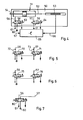
- FIG. 1 10 designates a linear drive.
- a cylinder housing 11 encloses a cylinder bore 12 in which a piston 13 runs.
- the piston 13 actuates a piston rod 14 which is guided on both sides through passage bores 15 and 16 in cylinder heads 17 and 18, respectively.
- One end 19 of the piston rod 14 carries a flange (not shown in FIG. 1) for connection to further drives or tools.
- An opposite end 20 of the piston rod 14 cooperates with a length measuring device 21, which is only schematically indicated in FIG. 1.
- the cylinder head 17 is provided with a lower installation space 30 which extends transversely to the longitudinal axis of the linear drive 10 and is connected to the cylinder bore 12 via a channel 31.
- an upper installation space 32 is provided in the cylinder head 17, from which, however, a channel 33 leads to a surface 41 of the cylinder head 17, which may be flange-shaped.
- the opposite cylinder head 18 is constructed identically to the cylinder head 17 and consequently has installation spaces 30a, 32a and channels 31a or 33a and a surface 41a.
- the surfaces 41 or 41a have a flange-like design, further drives or tools can be attached to them, as has already been described above for the flange at the end 19 of the piston rod 14.
- the linear drive 10 is then a link in a chain of drives and / or tools which, for example, form a handling device.
- a single-acting piston 13 can also be used in the exemplary embodiment according to FIG. 1, in which the piston 13 is supported, for example, with respect to the cylinder head 18 via a spring, and the installation space 30a then need not be provided.
- the valve cartridge 35 comprises a preliminary stage 36, which can be, for example, a torque motor, a moving coil, a moving coil-nozzle-baffle system or an electromagnet.
- the valve cartridge 35 also includes a main stage 37 which for example, a slide valve or a seat valve.
- a slide 38 can be seen which acts between an inflow 39 and an outflow 40.
- the installation space 30 therefore only needs to be provided from the outside with a control cable for the preliminary stage 36 and a compressed air connection for the main stage 37.
- the longitudinal axis of the slide 38 extends transversely to the longitudinal axis of the linear drive 10, so that with acceleration forces acting in the direction of the longitudinal axis of the linear drive 10 during operation of the drive there are no disturbances with regard to the axial position of the slide 38 can result.
- longitudinal channels 34 and 34a can also be provided running parallel to the cylinder bore 12.
- the longitudinal channel 34 can be provided for the pressure medium, for example compressed air, and the longitudinal channel 34a for receiving electrical control cables.
- Fig. 4 shows a schematic representation of the control of a linear drive 50 according to the invention, which works with a piston-cylinder unit 51, which is double-acting.
- a piston rod 52 cooperates at one end with a length measuring unit 53, while a working end 54 of the piston rod 52 is provided with a flange in the manner already mentioned.
- the piston-cylinder unit 51 is provided with a left port 56 and a right port 57 for the pressure medium.
- a 3/2-way servo valve 58 and 59 leads to the left port 56 and the right port 57, respectively.
- the two inputs of the valves 58, 59 are connected to a pressure source 60 and an outlet 61, respectively.
- Excitation coils 63 and 64 of the valves 58, 59 are connected to an electronic control device 65.
- a value which corresponds to the actual position value of the piston is fed to the control device 65 via a line 66 from the length measuring unit 53.
- a setpoint value can be supplied to the control device 65 via an input 67. From the difference between the target value and the actual value, the control device 65 forms signals with which the coils 63 and 64 are controlled.
- valves 58, 59 are in the position shown in FIG. 4, the piston is pressurized on both sides and remains in the position shown.
- the left connection 56 is connected to the outlet 61 and the piston can move to the left.
- valves 58, 59 are designed as directional servo valves.
- valves 70, 71 are connected in the same way as already shown in FIG. 4, but valves 70, 71 are designed as pressure servo valves. for which purpose lines 72 and 73 are led from the connections 56 and 57 to the end face of the slide of the valves 70, 71.
- This internal pressure feedback leads to an improvement in the control behavior, so that adjustment problems which can occasionally occur with the directional servo valves 58, 59 according to FIG. 4 are avoided.
- the further variant according to FIG. 6 now represents a combination of the two variants according to FIGS. 4 and 5, because a pressure servo valve 75 is provided at port 56 and a directional servo valve 76 is provided at port 57.
- a common 4/3-way servo valve 80 is used instead of two valves, in the middle switching position shown in FIG. 7, both connections 56, 57 are blocked. Switches that However, valve 80, for example to the right, connections 56, 57 are connected crosswise to pressure source 60 and outlet 61, respectively, and the piston (see FIG. 4) moves to the right.
- a piston-cylinder unit 85 which has a single-acting piston 86.
- the piston 86 is supported to the right by a spring 87, and therefore only a single valve, in the exemplary embodiment namely a 3/2-way servo valve 88, is required, which is connected via a connection 89 to the piston 86 to the left Pressure chamber is connected.
- the valve 88 In the position of the valve 88 shown in FIG. 8, the piston 86 is moved to the right against the force of the spring 87, and a rest position of the piston 86 can be achieved by cyclically switching the valve 88.
Landscapes
- Engineering & Computer Science (AREA)
- Physics & Mathematics (AREA)
- Fluid Mechanics (AREA)
- Mechanical Engineering (AREA)
- General Engineering & Computer Science (AREA)
- Actuator (AREA)
- Servomotors (AREA)
- Fluid-Pressure Circuits (AREA)
Applications Claiming Priority (2)
| Application Number | Priority Date | Filing Date | Title |
|---|---|---|---|
| DE3436946A DE3436946C2 (de) | 1984-10-09 | 1984-10-09 | Linearantrieb |
| DE3436946 | 1984-10-09 |
Publications (2)
| Publication Number | Publication Date |
|---|---|
| EP0177876A1 true EP0177876A1 (fr) | 1986-04-16 |
| EP0177876B1 EP0177876B1 (fr) | 1989-10-11 |
Family
ID=6247430
Family Applications (1)
| Application Number | Title | Priority Date | Filing Date |
|---|---|---|---|
| EP85112396A Expired EP0177876B1 (fr) | 1984-10-09 | 1985-10-01 | Entraînement linéaire |
Country Status (4)
| Country | Link |
|---|---|
| US (1) | US5016519A (fr) |
| EP (1) | EP0177876B1 (fr) |
| JP (1) | JPH0665883B2 (fr) |
| DE (1) | DE3436946C2 (fr) |
Cited By (3)
| Publication number | Priority date | Publication date | Assignee | Title |
|---|---|---|---|---|
| DE3524414A1 (de) * | 1985-04-16 | 1986-10-23 | GAS Gesellschaft für Antriebs- und Steuerungstechnik mbH & Co KG, 7742 St Georgen | Linearantrieb |
| EP0519185A1 (fr) * | 1991-06-19 | 1992-12-23 | Robert Bosch Gmbh | Vérin commandé par un fluide sous pression |
| WO1996031704A1 (fr) * | 1995-04-01 | 1996-10-10 | Peters Indu-Produkt Elektrotechnik-Elektronic Gmbh | Actionneur pour verin de commande |
Families Citing this family (11)
| Publication number | Priority date | Publication date | Assignee | Title |
|---|---|---|---|---|
| DE3436946C2 (de) * | 1984-10-09 | 1994-06-09 | Mannesmann Ag | Linearantrieb |
| DE3507167C3 (de) * | 1985-03-01 | 1996-06-13 | Festo Kg | Kolben-Zylinder-Anordnung |
| DE3709173A1 (de) * | 1987-03-20 | 1988-09-29 | Knorr Bremse Ag | Doppeltwirkender druckmittelzylinder |
| DE3741425C3 (de) * | 1987-12-08 | 1997-12-04 | Mannesmann Ag | Linearantrieb |
| DE4041370C2 (de) * | 1990-12-20 | 1995-06-01 | Mannesmann Ag | Profilrohr für kolbenstangenlosen Arbeitszylinder |
| DE4108158C2 (de) * | 1991-03-14 | 2002-11-28 | Festo Ag & Co | Linear-Antriebsvorrichtung |
| JPH05111884A (ja) * | 1991-10-21 | 1993-05-07 | Matsushita Electric Ind Co Ltd | 移行装置 |
| KR200276748Y1 (ko) * | 2001-12-07 | 2002-05-27 | 박외숙 | 환봉형 체인 로드레스 실린더 |
| US7980269B2 (en) | 2008-12-03 | 2011-07-19 | Robert Bosch Gmbh | Control valve assembly for load carrying vehicles |
| US9120492B2 (en) | 2008-12-03 | 2015-09-01 | Aventics Corporation | Control valve assembly for load carrying vehicles |
| DE102013006231A1 (de) * | 2013-04-11 | 2014-10-16 | Liebherr-Components Kirchdorf GmbH | Arbeitszylinder und Baumaschine bzw. Hebezeug |
Citations (8)
| Publication number | Priority date | Publication date | Assignee | Title |
|---|---|---|---|---|
| US2976852A (en) * | 1959-09-21 | 1961-03-28 | Modernair Corp | Valve-in-head pneumatic cylinder |
| GB889149A (en) * | 1958-11-21 | 1962-02-07 | Lawrence Henry Gardner | Improvements in or relating to fluid control valves |
| US3060901A (en) * | 1960-05-31 | 1962-10-30 | Ling Temco Vought Inc | Hydraulic actuator with integrally housed valve |
| US3233523A (en) * | 1962-10-17 | 1966-02-08 | Scovill Manufacturing Co | Fluid cylinder and valve control means therefor |
| FR1436078A (fr) * | 1965-03-10 | 1966-04-22 | Crouzet Sa | Dispositif permettant l'adaptation d'un distributeur quatre voies 5 orifices à l'arrière d'un vérin pouvant être normalisé |
| DE2918294A1 (de) * | 1978-05-12 | 1979-11-15 | Parisienne Outillage | Zylinder fuer ein pneumatikelement |
| DE3130056A1 (de) * | 1981-07-30 | 1983-02-10 | Festo-Maschinenfabrik Gottlieb Stoll, 7300 Esslingen | Steuerventilanordnung fuer einen druckmittel-arbeitszylinder |
| DE8310037U1 (de) * | 1984-09-13 | Robert Bosch Gmbh, 7000 Stuttgart | Arbeitszylinder |
Family Cites Families (37)
| Publication number | Priority date | Publication date | Assignee | Title |
|---|---|---|---|---|
| US696691A (en) * | 1901-06-22 | 1902-04-01 | John G Mccormack | Valve for engines. |
| US763586A (en) * | 1903-07-20 | 1904-06-28 | Leon R Alleman | Cylinder for steam-engines. |
| US1137455A (en) * | 1912-12-29 | 1915-04-27 | Sf Bowser & Co Inc | Adjustable pointer and stop for pumps and the like. |
| US1582022A (en) * | 1923-03-03 | 1926-04-27 | Teresa Catherine Adams | Expansible-chamber motor |
| US2457930A (en) * | 1944-07-17 | 1949-01-04 | Cons Vultee Aircraft Corp | Fluid pressure operated device for inserting cushion pads |
| US2551453A (en) * | 1945-05-31 | 1951-05-01 | Int Harvester Co | Fluid-actuated ram couple |
| US2948298A (en) * | 1958-11-21 | 1960-08-09 | Lawrence H Gardner | Valve |
| US2997066A (en) * | 1959-04-30 | 1961-08-22 | Ross Operating Valve Co | Fluid-actuated shiftable mechanism |
| GB948463A (en) * | 1959-06-26 | 1964-02-05 | Westinghouse Air Brake Co | Improvements relating to railway traffic controlling apparatus |
| DE2062134C3 (de) * | 1970-12-17 | 1974-03-28 | Hartmann & Laemmle Ohg, 7000 Stuttgart-Bad Cannstatt | Steuervorrichtung mit einer mit einem Kolben eines Arbeitszylinders verbundenen MeßspindeL |
| US3956973A (en) * | 1972-07-11 | 1976-05-18 | Basic Aluminum Castings Company | Die casting machine with piston positioning control |
| DE2308291C3 (de) * | 1973-02-20 | 1979-04-05 | Research Engineering Co., Houston, Tex. (V.St.A.) | Stellantrieb mit Rfickschnellf ederung für Ventile u.dgl |
| DE2506793A1 (de) * | 1975-02-18 | 1976-08-26 | Knorr Bremse Gmbh | Betaetigungszylinder mit angebautem 4/2-wege-ventil fuer pneumatische getriebeschaltung |
| JPS523987A (en) * | 1975-06-27 | 1977-01-12 | Kondo Seisakusho:Kk | Hydraulic drive device |
| JPS5210561A (en) * | 1975-07-15 | 1977-01-26 | Tohoku Oki Electric Co | Accdc selffmaintaining electromagnetic solenoid |
| DE2648608C3 (de) * | 1976-10-27 | 1979-11-29 | Walter Hunger Kg, 8770 Lohr | Steuereinrichtung für einen Differentialzylinder |
| US4121504A (en) * | 1977-01-21 | 1978-10-24 | Inovec, Inc. | Cylinder positioning systems |
| DE2730933C3 (de) * | 1977-07-08 | 1981-01-15 | Wolfgang Prof. Dr.-Ing. 5100 Aachen Backe | Membran-Blutpumpe mit integriertem elektropneumatischem Servoventil |
| US4154262A (en) * | 1977-10-17 | 1979-05-15 | Gresen Manufacturing Company | Hydraulic control system |
| SU669095A1 (ru) * | 1977-11-01 | 1979-06-25 | Ленинградское Специальное Конструкторское Бюро Полимерного Машиностроения | Гидропривод |
| DE2914650A1 (de) * | 1979-04-11 | 1980-10-23 | Bosch Gmbh Robert | Uebergabegeraet zum zufuehren und weitergeben von serienteilen |
| DE2916191A1 (de) * | 1979-04-21 | 1980-10-23 | Horst Knaebel | Krafteinheit als antriebsvorrichtung, z.b. zum umformen, verformen, verdichten, schlagen und antreiben |
| DE2933557C2 (de) * | 1979-08-18 | 1982-11-04 | Robert Bosch Gmbh, 7000 Stuttgart | Meßumformer zur berührungslosen Weg- oder Geschwindigkeitsmessung |
| JPS57192603A (en) * | 1981-05-23 | 1982-11-26 | Shoketsu Kinzoku Kogyo Co Ltd | Fluid pressure cylinder control device |
| US4422474A (en) * | 1981-09-14 | 1983-12-27 | Ford Motor Company | Electro-hydraulic remote valve |
| JPS58131408A (ja) * | 1982-01-29 | 1983-08-05 | Hitachi Ltd | アクチユエ−タ装置 |
| DE3216693A1 (de) * | 1982-05-05 | 1983-11-10 | Kienzle Apparate Gmbh, 7730 Villingen-Schwenningen | Elektropneumatisches servoventil zur steuerung eines volumenstromes bzw. eines druckes |
| US4493244A (en) * | 1982-06-09 | 1985-01-15 | Wabco Fahrzeugbremsen Gmbh | Pneumatic door operator |
| DE3235784C2 (de) * | 1982-09-28 | 1984-10-31 | Festo-Maschinenfabrik Gottlieb Stoll, 7300 Esslingen | Druckmittelbetätigter doppeltwirkender Arbeitszylinder |
| DE3317113A1 (de) * | 1983-05-10 | 1984-11-15 | Knorr-Bremse GmbH, 8000 München | Positioniereinrichtung fuer kolbenstangenlose zylinder |
| DE3326098A1 (de) * | 1983-07-20 | 1985-02-07 | Heinz 8775 Partenstein Tepass | Zylinder mit geschlossenem hydrauliksystem |
| AT384899B (de) * | 1984-09-17 | 1988-01-25 | Hoerbiger Ventilwerke Ag | Regelungsverfahren fuer einen fluidzylinder |
| DE3436946C2 (de) * | 1984-10-09 | 1994-06-09 | Mannesmann Ag | Linearantrieb |
| DE3514074A1 (de) * | 1985-04-18 | 1986-10-23 | Herion-Werke Kg, 7012 Fellbach | Kolbenstangenloser zylinder |
| US4593605A (en) * | 1985-06-07 | 1986-06-10 | Fmc Corporation | Fluid power transfer device |
| DE3533697A1 (de) * | 1985-09-21 | 1987-03-26 | Axel Dipl Ing Dr Ing Schulte | Druckregelvorrichtung |
| DE3619473A1 (de) * | 1986-06-10 | 1987-12-17 | Knorr Bremse Ag | Druckmittelgetriebener, kolbenstangenloser arbeitszylinder |
-
1984
- 1984-10-09 DE DE3436946A patent/DE3436946C2/de not_active Revoked
-
1985
- 1985-10-01 EP EP85112396A patent/EP0177876B1/fr not_active Expired
- 1985-10-09 JP JP60223886A patent/JPH0665883B2/ja not_active Expired - Lifetime
-
1987
- 1987-12-18 US US07/113,644 patent/US5016519A/en not_active Expired - Fee Related
Patent Citations (8)
| Publication number | Priority date | Publication date | Assignee | Title |
|---|---|---|---|---|
| DE8310037U1 (de) * | 1984-09-13 | Robert Bosch Gmbh, 7000 Stuttgart | Arbeitszylinder | |
| GB889149A (en) * | 1958-11-21 | 1962-02-07 | Lawrence Henry Gardner | Improvements in or relating to fluid control valves |
| US2976852A (en) * | 1959-09-21 | 1961-03-28 | Modernair Corp | Valve-in-head pneumatic cylinder |
| US3060901A (en) * | 1960-05-31 | 1962-10-30 | Ling Temco Vought Inc | Hydraulic actuator with integrally housed valve |
| US3233523A (en) * | 1962-10-17 | 1966-02-08 | Scovill Manufacturing Co | Fluid cylinder and valve control means therefor |
| FR1436078A (fr) * | 1965-03-10 | 1966-04-22 | Crouzet Sa | Dispositif permettant l'adaptation d'un distributeur quatre voies 5 orifices à l'arrière d'un vérin pouvant être normalisé |
| DE2918294A1 (de) * | 1978-05-12 | 1979-11-15 | Parisienne Outillage | Zylinder fuer ein pneumatikelement |
| DE3130056A1 (de) * | 1981-07-30 | 1983-02-10 | Festo-Maschinenfabrik Gottlieb Stoll, 7300 Esslingen | Steuerventilanordnung fuer einen druckmittel-arbeitszylinder |
Cited By (3)
| Publication number | Priority date | Publication date | Assignee | Title |
|---|---|---|---|---|
| DE3524414A1 (de) * | 1985-04-16 | 1986-10-23 | GAS Gesellschaft für Antriebs- und Steuerungstechnik mbH & Co KG, 7742 St Georgen | Linearantrieb |
| EP0519185A1 (fr) * | 1991-06-19 | 1992-12-23 | Robert Bosch Gmbh | Vérin commandé par un fluide sous pression |
| WO1996031704A1 (fr) * | 1995-04-01 | 1996-10-10 | Peters Indu-Produkt Elektrotechnik-Elektronic Gmbh | Actionneur pour verin de commande |
Also Published As
| Publication number | Publication date |
|---|---|
| DE3436946C2 (de) | 1994-06-09 |
| JPS6192302A (ja) | 1986-05-10 |
| EP0177876B1 (fr) | 1989-10-11 |
| JPH0665883B2 (ja) | 1994-08-24 |
| US5016519A (en) | 1991-05-21 |
| DE3436946A1 (de) | 1986-04-10 |
Similar Documents
| Publication | Publication Date | Title |
|---|---|---|
| EP1758007B1 (fr) | Régulateur de position actionné par fluide | |
| EP0854982B1 (fr) | Systeme de soupapes | |
| DE102008014964B4 (de) | Positionssteuermechanismus für doppelt wirkende Pneumatikzylinder | |
| DE3688598T2 (de) | Vorrichtungen zur Dämpfung von Kolbenbewegungen. | |
| DE3114437C2 (de) | Druckregelventil | |
| DE3436946C2 (de) | Linearantrieb | |
| DE1916224C3 (de) | Hydrostatisches Getriebe | |
| DE2933704A1 (de) | Druckmittelverbindung zwischen einem ventilblock und einem zumindest einen doppelt wirkenden druckmittelmotor aufweisenden verbraucher | |
| DE102017117335A1 (de) | Betätigungseinheit für ein Prozessventil sowie Prozessventil | |
| EP1500825B1 (fr) | Distributeur à voies multiples | |
| EP0342410A2 (fr) | Soupape de sûreté | |
| DE102019110917A1 (de) | Hydrostatisches Linear-Antriebssystem | |
| DE102021213469B3 (de) | Sicherheitsventileinrichtung | |
| DE4011908C3 (de) | Mehrwegeventil | |
| DE2440555C2 (de) | Hydraulischer Steuerkreis | |
| DE3704312A1 (de) | Elektrohydraulische steueranordnung | |
| DE3800990A1 (de) | Handhabungsgeraet | |
| DE10210306A1 (de) | Anordnung zur aktiven Rollstabilisierung eines Kraftfahrzeugs | |
| EP0347562A2 (fr) | Soupape de sûreté | |
| DE3741425C2 (fr) | ||
| DE3835010C2 (fr) | ||
| DE4422528A1 (de) | Fluidbetätigte Antriebseinheit | |
| DE20108382U1 (de) | Linearantrieb | |
| DE19757157C2 (de) | Hydraulischer Linearantrieb | |
| DE3736750C2 (fr) |
Legal Events
| Date | Code | Title | Description |
|---|---|---|---|
| PUAI | Public reference made under article 153(3) epc to a published international application that has entered the european phase |
Free format text: ORIGINAL CODE: 0009012 |
|
| AK | Designated contracting states |
Kind code of ref document: A1 Designated state(s): BE CH FR GB IT LI NL SE |
|
| 17P | Request for examination filed |
Effective date: 19861014 |
|
| 17Q | First examination report despatched |
Effective date: 19870508 |
|
| GRAA | (expected) grant |
Free format text: ORIGINAL CODE: 0009210 |
|
| AK | Designated contracting states |
Kind code of ref document: B1 Designated state(s): BE CH FR GB IT LI NL SE |
|
| ET | Fr: translation filed | ||
| GBT | Gb: translation of ep patent filed (gb section 77(6)(a)/1977) | ||
| ITF | It: translation for a ep patent filed | ||
| PLBE | No opposition filed within time limit |
Free format text: ORIGINAL CODE: 0009261 |
|
| STAA | Information on the status of an ep patent application or granted ep patent |
Free format text: STATUS: NO OPPOSITION FILED WITHIN TIME LIMIT |
|
| 26N | No opposition filed | ||
| PGFP | Annual fee paid to national office [announced via postgrant information from national office to epo] |
Ref country code: BE Payment date: 19930916 Year of fee payment: 9 |
|
| ITTA | It: last paid annual fee | ||
| PGFP | Annual fee paid to national office [announced via postgrant information from national office to epo] |
Ref country code: NL Payment date: 19931031 Year of fee payment: 9 |
|
| PG25 | Lapsed in a contracting state [announced via postgrant information from national office to epo] |
Ref country code: BE Effective date: 19941031 |
|
| EAL | Se: european patent in force in sweden |
Ref document number: 85112396.8 |
|
| BERE | Be: lapsed |
Owner name: GAS G-. FUR ANTRIEBS UND STEUERUNGSTECHNIK M.B.H. Effective date: 19941031 |
|
| PG25 | Lapsed in a contracting state [announced via postgrant information from national office to epo] |
Ref country code: NL Effective date: 19950501 |
|
| NLV4 | Nl: lapsed or anulled due to non-payment of the annual fee | ||
| PGFP | Annual fee paid to national office [announced via postgrant information from national office to epo] |
Ref country code: GB Payment date: 19960916 Year of fee payment: 12 |
|
| PGFP | Annual fee paid to national office [announced via postgrant information from national office to epo] |
Ref country code: FR Payment date: 19960920 Year of fee payment: 12 Ref country code: CH Payment date: 19960920 Year of fee payment: 12 |
|
| PGFP | Annual fee paid to national office [announced via postgrant information from national office to epo] |
Ref country code: SE Payment date: 19960923 Year of fee payment: 12 |
|
| PG25 | Lapsed in a contracting state [announced via postgrant information from national office to epo] |
Ref country code: GB Free format text: LAPSE BECAUSE OF NON-PAYMENT OF DUE FEES Effective date: 19971001 |
|
| PG25 | Lapsed in a contracting state [announced via postgrant information from national office to epo] |
Ref country code: SE Free format text: LAPSE BECAUSE OF NON-PAYMENT OF DUE FEES Effective date: 19971002 |
|
| PG25 | Lapsed in a contracting state [announced via postgrant information from national office to epo] |
Ref country code: LI Free format text: LAPSE BECAUSE OF NON-PAYMENT OF DUE FEES Effective date: 19971031 Ref country code: FR Free format text: THE PATENT HAS BEEN ANNULLED BY A DECISION OF A NATIONAL AUTHORITY Effective date: 19971031 Ref country code: CH Free format text: LAPSE BECAUSE OF NON-PAYMENT OF DUE FEES Effective date: 19971031 |
|
| GBPC | Gb: european patent ceased through non-payment of renewal fee |
Effective date: 19971001 |
|
| REG | Reference to a national code |
Ref country code: CH Ref legal event code: PL |
|
| EUG | Se: european patent has lapsed |
Ref document number: 85112396.8 |
|
| REG | Reference to a national code |
Ref country code: FR Ref legal event code: ST |