EP0343733A1 - Système de régulation d'un écran de visualisation - Google Patents
Système de régulation d'un écran de visualisation Download PDFInfo
- Publication number
- EP0343733A1 EP0343733A1 EP89201281A EP89201281A EP0343733A1 EP 0343733 A1 EP0343733 A1 EP 0343733A1 EP 89201281 A EP89201281 A EP 89201281A EP 89201281 A EP89201281 A EP 89201281A EP 0343733 A1 EP0343733 A1 EP 0343733A1
- Authority
- EP
- European Patent Office
- Prior art keywords
- supplied
- screen
- deflection means
- signals
- signal
- Prior art date
- Legal status (The legal status is an assumption and is not a legal conclusion. Google has not performed a legal analysis and makes no representation as to the accuracy of the status listed.)
- Ceased
Links
Images

Classifications
-
- G—PHYSICS
- G01—MEASURING; TESTING
- G01R—MEASURING ELECTRIC VARIABLES; MEASURING MAGNETIC VARIABLES
- G01R13/00—Arrangements for displaying electric variables or waveforms
- G01R13/20—Cathode-ray oscilloscopes
- G01R13/22—Circuits therefor
-
- G—PHYSICS
- G01—MEASURING; TESTING
- G01R—MEASURING ELECTRIC VARIABLES; MEASURING MAGNETIC VARIABLES
- G01R13/00—Arrangements for displaying electric variables or waveforms
- G01R13/20—Cathode-ray oscilloscopes
- G01R13/22—Circuits therefor
- G01R13/28—Circuits for simultaneous or sequential presentation of more than one variable
Definitions
- the invention relates to a system for controlling the position and intensity of an electron beam in a display tube of a display unit in such a manner that both analog signals as well as alphanumeric characters can be made visible simultaneously on the screen of the display tube, the display unit comprising X-deflection means for deflecting the electron beam in the X-direction, Y-deflection means for deflecting the electron beam in the Y-direction and Z-control means for controlling the intensity of the light spot, written by the electron beam on the screen of the display tube.
- the first category relates to systems in which an XY-control method is applied.
- This category covers for instance oscilloscopes.
- the deflection yoke used for deflecting the electron beam in the X-direction is supplied with a sawtooth shaped signal, whereas the deflection yoke for deflection in the Y-direction is supplied with the analog signal to be displayed. If furthermore during the slope of the sawtooth shaped control signal the intensity of the display picture is controlled at a visible level than on the screen a display of the analog signal will be obtained.
- another control signal can be supplied, for instance for displaying so-called Lissajous-figures or other types of the vector displays onto the screen.
- the second category of said mentioned systems covers for instance television sets.
- the X-deflection yoke is supplied with a relatively high frequency sawtooth shaped signal
- the Y-deflection yoke is supplied with a relatively low frequency saw tooth shaped signal.
- both sawtooth shaped signals will take care that the electron beam in a known way scans the whole screen of the cathode ray tube one line after the other.
- the actual picture signal is supplied to the intensity control means which will take care that during the scanning of the screen each pixel of the screen obtains the correct intensity.
- a display unit functioning according to the image scanning method has to be used for displaying analog signals than in a disadvantageous way the analog signals are sampled by the line scanning, with the result that minor details of the analog signals will be lost. This is visible on each normal television screen.
- the purpose of the invention is now to provide a system for controlling the position and intensity of an electron beam in a cathode ray tube of a display unit in such a way that on the one hand analog signals can be displayed without loss of details, whereas on the other hand in a very simple way alpha-numeric symbols can be displayed both at arbitrarely selectable positions on the screen of the display unit.
- the system of the above-mentioned type is characterized in that the period necessary for displaying a complete picture on the screen of the display tube is divided in two successive sub periods, a first sub period in which a sawtooth shaped signal is supplied to the X-deflection means, a number of analog signals superimposed onto a staircase bias signal is supplied to the Y-deflection means, the number of sawtooth slopes in said sawtooth shaped signal being equal to said number of analog signals, and a line fligh back suppression signal is delivered to the Z-control means, thereby obtaining an X-Y-control of the electron beam, and a second sub period in which a first further sawtooth shaped signal is supplied to the X-deflection means, a second further sawtooth shaped signal is supplied to the Y-deflection means and alphanumeric character control signals are supplied to the Z-control means, thereby obtaining an image scanning control of the electron beam.
- an XY-control method is used whereby one or more analog signals can be displayed on the screen without loss of any details. Also during said first period for instance Lissajous-figures or other vector displays can be made visible on the screen. Thereby arbitrarily the whole screen or a part of the screen can be used. If only a part of the screen is used, than the deflection can be restricted to that specific part of the screen with the result that said first period can be shortened.
- an image scanning method is used whereby at predetermined positions alpha-numeric symbols are displayed on the screen. Also in this period the whole screen can be scanned or only a part thereof, but in general scanning of the whole screen in this image scanning period will be preferred.
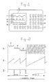
- Figure 1 illustrates schematically an example of a picture which in agreement with the invention can be made visible onto the screen of a display system.
- the picture comprises within the frame 10 a number of analog signals 11, 12 and 13 and outside the frame alpha-numeric symbols are displayed at various positions, such as the rows of symbols 14, 15, 16, and the subscript 17 as well as the highlighted rectangles at the left side of the frame 10 one of which is referenced by 18.
- the actual contents of the rows of alpha-numeric symbols 14 until 18 is not relevant within the scope of the invention.
- the rows 14, 15, 16 can be related for instance to the analog signals 11, 12 and 13 displayed at the left side thereof.
- the subscript 17 may give an explanation of the picture as whole whereas the rectangles 18 can be destined for instance as selectable touch pads if a so-called "touch screen" is used.
- figure 2 indicates in which way the picture illustrated in figure 1 can be displayed.
- the X-control signal, Y-control signal and Z-control signal, (intensity control) are shown one underneath the other.
- Each of these three signals is in fact periodical, the period of these signals being equal to the image repetition frequency.
- the image repetition frequency is preferably larger than 25 Hz and more specifically larger than 50 Hz.
- the shape of the signals necessary to build one complete image is illustrated.
- Within one image two display periods can be distinguished, which in figure 2 are inidicated as period 1 and period 2.
- the analog signals inside frame 10 are displayed and within period 2 the various alpha-numeric symbols outside frame 10 are displayed.
- the X-control signal consists of a number of sawtooth shaped signals, the number of which equals the number of analog signals to be displayed (in the underlying example three signals, i.e. the analog signals 11, 12 and 13 have to be displayed).
- the Y-deflection signal is formed by the succeeding analog signal parts 11′, 12′ and 13′ which are superimposed onto a staircase shaped dc-component. It will be clear for the expert in this field that the combination of these X- and Y-control signals within period 1 will result into the display of the analog signals 11, 12 and 13 underneath each other as is indicated in figure 1.
- the X-control signal is formed by one single slope of a relatively low frequency sawtooth shaped signal, whereas the Y-signal consists of a relatively high frequency sawtooth shaped signal. It will be clear for the expert in this field that the combination of the these X- and Y-control signals results in a line for line scanning of the whole picture on the screen, whereby in contrast to a normal television picture the scanning lines are running vertically on the screen of the cathode ray tube. If during this period 2 a suitable Z-control signal is supplied then predetermined pixels will be controlled light and dark in correspondence with this Z-control signal, which with suitable control information results into the display of the desired rows of alpha-numeric symbols 14 until 18.
- the Z-signal is within period 2 indicated schematically in figure 2. If it is not necessary to display alpha-numeric characters inside the frame 10, then within fram 10 the electron beam will be controlled to a dark intensity by the Z-control signal. This is however, not a very stringent requirement. Within the scope of the invention it is also possible to display alpha-numeric characters inside the frame 10, for instance to attrack attention to parts of the analog signals 11, 12 and 13.
- the scanning lines during period 2 are running vertically. Vertically running scanning lines are selected because therewith the X-control signal comprises only relatively low frequency components whereas all relatively high frequency components are combined in the Y-control signal.
- the result thereof is that only the Y-driver stages, the Y-amplifiers and the deflection yoke have to be developed and embodied such that high frequency signals can be processed.
- the drivers, amplifiers and yokes for the X-deflection have to be suitable only for the processing of relatively low frequency signals and have to satisfy therefore much lower requirements.
- FIG. 3 A system in which the control method according to the invention can be brought into practice is schematically illustrated in figure 3.
- the system comprises a cathode ray 20 with an X-deflection yoke 21 and an Y-deflection yoke 22 around the neck of the tube.
- the tube 20 comprises furthermore one or more electrodes 23 to which signals for the intensity control (the so-called Z-control signals) have to be supplied.
- the X-deflection yoke receives through the switch 24 sawtooth signals supplied either by the generator 25 or by the generator 26.
- the generator 25 supplies sawtooth shaped deflection signals by means of which during the period 1 the analog signals 11, 12 and 13 are written on the screen of the cathode ray 20.
- the generator 26 supplies the relatively low frequency sawtooth signal which during period 2 is used to shift the vertical scanning lines in horizontal direction.
- the vertical deflection yoke system 22 receives signals through the switch 27.
- the signal inputs 28, 29 and 30 receive the respective analog signals 11, 12 and 13 which after amplification in the amplifiers 31, 32 and 33 are delivered to a multiplexer 34.
- the function of this multiplexer 34 is to supply the signals at the inputs 28, 29 and 30 in successive order to a summing point 35 in which these analog signals are combined with a staircase signal delivered by the generator 36. It will be clear that at the output of the summing point 35 a signal appears with the shape as is illustrated in figure 2 within period 1 of the Y-control signal. This signal is through the switch 27 supplied to the Y-deflection yoke 22.
- the switch 27 guides signals from the sawtooth generator 27 to the Y-deflection yoke. These sawtooth signals produce the line scanning signals during period 2.
- the intensity control signals are supplied to the thereto destined electrodes 23 through a switch 38.
- the switch 38 guides the signals from a generator 39 by means of which the analog signals 11, 12 and 13 are displayed with visible intensity whereas during the line-flyback period the signals are suppressed by means of negative pulses.
- the switch 38 guides the control signals from a microprocessor 40 which in turn receives input signals through input 41.
- the mircroprocessor 40 generates the suitable control signals for displaying a number of alpha-numeric characters dependent on input signals on the input 41. It is for instance possible that the input 41 is connected to suitable input means such as a keyboard, etc.
- the generation of control signals for displaying alpha-numeric characters by means of a microprocessor 40 is considered as known to the expert in this field.
- the switches 24, 27 and 38 are controlled synchroneously by a switch control unit 42 in such a manner that during period 1 the switches are in the position illlustrated in figure 2.
- the control signal source 42 will take care that during period 2 all the switches 24, 27 and 38 are switched over to the other position which is not illustrated in figure 2.
- alpha-numeric characters can be displayed superimposed onto the analog signals.
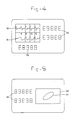
- these alpha-numeric characters can be shaped as lines or line-segments as well as other graphical elements. Therewith for instance a picture can be realized as is schematically indicated in figure 4.
- a part of the screen is used to display analog signals 50 and 51 and around this part rows of alpha-numeric symbols are displayed, which in figure 4 are referenced by 52 en 53.
- a dividing grid is displayed during period 2 comprising for instance in the center a horizontal scale whereby scale values (0, 5, 10) are made visible.
- FIG 5 An other possible picture on the screen is displayed in figure 5. Also in this case one can distinguish between a part of the screen inside the frame 60 in which Lissajous-figures, such as 61 in figure 4 can be displayed, and the part outside the frame 60 where alpha-numeric information 62 is displayed. It will be clear for the expert in this field that for presenting Lissajous-figures a modified version of the system in figure 3 will be necessary. Especially the sawtooth generator 26 will have to be replaced by an amplifier for processing an external control signal or by a suitable signal generator.
- the system according to the invention can for instance be used in a monitor unit for medical applications, used for instance to display simultaneously the heart beat, breathing movements, blood pressure, etc., together with alpha-numeric information relating to these signals. Monitors like these are known as such.
Landscapes
- Physics & Mathematics (AREA)
- General Physics & Mathematics (AREA)
- Details Of Television Scanning (AREA)
- Cathode-Ray Tubes And Fluorescent Screens For Display (AREA)
Applications Claiming Priority (2)
| Application Number | Priority Date | Filing Date | Title |
|---|---|---|---|
| NL8801319A NL8801319A (nl) | 1988-05-20 | 1988-05-20 | Inrichting voor het sturen van een beeldbuis. |
| NL8801319 | 1988-05-20 |
Publications (1)
| Publication Number | Publication Date |
|---|---|
| EP0343733A1 true EP0343733A1 (fr) | 1989-11-29 |
Family
ID=19852334
Family Applications (1)
| Application Number | Title | Priority Date | Filing Date |
|---|---|---|---|
| EP89201281A Ceased EP0343733A1 (fr) | 1988-05-20 | 1989-05-19 | Système de régulation d'un écran de visualisation |
Country Status (4)
| Country | Link |
|---|---|
| US (1) | US5053684A (fr) |
| EP (1) | EP0343733A1 (fr) |
| JP (1) | JPH0242365A (fr) |
| NL (1) | NL8801319A (fr) |
Families Citing this family (8)
| Publication number | Priority date | Publication date | Assignee | Title |
|---|---|---|---|---|
| CA2056139C (fr) * | 1991-01-31 | 2000-08-01 | Eveready Battery Company, Inc. | Detecteur d'etat de charge a couche mince electrochromique a placer directement sur une pile |
| JPH0767122A (ja) * | 1993-06-18 | 1995-03-10 | Pioneer Electron Corp | コンバーゼンス調整装置 |
| US5618441A (en) * | 1995-06-07 | 1997-04-08 | Rosa; Jim | Single microcontroller execution of control and safety system functions in a dialysis machine |
| US5620608A (en) * | 1995-06-07 | 1997-04-15 | Cobe Laboratories, Inc. | Information entry validation system and method for a dialysis machine |
| US6219029B1 (en) * | 1998-04-03 | 2001-04-17 | Tektronix, Inc. | Emphasizing infrequent events in a digital oscilloscope having variable intensity rasterizer and variable intensity or color display |
| US6605811B2 (en) * | 2001-11-09 | 2003-08-12 | Elionix Inc. | Electron beam lithography system and method |
| US9180238B2 (en) * | 2008-06-11 | 2015-11-10 | Baxter International Inc. | Distributed processing system and method for dialysis machines |
| JP2018524718A (ja) | 2015-06-25 | 2018-08-30 | ガンブロ・ルンディア・エービーGambro Lundia Ab | 分散データベースを有する医療装置システム及び方法 |
Citations (3)
| Publication number | Priority date | Publication date | Assignee | Title |
|---|---|---|---|---|
| FR2472799A1 (fr) * | 1979-12-27 | 1981-07-03 | Radiologie Cie Gle | Dispositif a memoire pour la visualisation d'informations analogiques et numeriques |
| US4331962A (en) * | 1980-09-12 | 1982-05-25 | Siemens Aktiengesellschaft | Device for gating a blanking bar into a recording of analog signals |
| EP0260780A1 (fr) * | 1986-09-17 | 1988-03-23 | Tektronix, Inc. | Système de mesure du niveau d'un signal basé sur un oscilloscope |
Family Cites Families (2)
| Publication number | Priority date | Publication date | Assignee | Title |
|---|---|---|---|---|
| US3599033A (en) * | 1969-09-22 | 1971-08-10 | Hewlett Packard Co | System for simultaneous display of ecg and heart rate |
| US4821030A (en) * | 1986-12-19 | 1989-04-11 | Tektronix, Inc. | Touchscreen feedback system |
-
1988
- 1988-05-20 NL NL8801319A patent/NL8801319A/nl not_active Application Discontinuation
-
1989
- 1989-05-19 EP EP89201281A patent/EP0343733A1/fr not_active Ceased
- 1989-05-19 US US07/354,276 patent/US5053684A/en not_active Expired - Fee Related
- 1989-05-20 JP JP1127735A patent/JPH0242365A/ja active Pending
Patent Citations (3)
| Publication number | Priority date | Publication date | Assignee | Title |
|---|---|---|---|---|
| FR2472799A1 (fr) * | 1979-12-27 | 1981-07-03 | Radiologie Cie Gle | Dispositif a memoire pour la visualisation d'informations analogiques et numeriques |
| US4331962A (en) * | 1980-09-12 | 1982-05-25 | Siemens Aktiengesellschaft | Device for gating a blanking bar into a recording of analog signals |
| EP0260780A1 (fr) * | 1986-09-17 | 1988-03-23 | Tektronix, Inc. | Système de mesure du niveau d'un signal basé sur un oscilloscope |
Also Published As
| Publication number | Publication date |
|---|---|
| JPH0242365A (ja) | 1990-02-13 |
| US5053684A (en) | 1991-10-01 |
| NL8801319A (nl) | 1989-12-18 |
Similar Documents
| Publication | Publication Date | Title |
|---|---|---|
| DE2760261C2 (de) | Raster-Anzeigevorrichtung | |
| US5053684A (en) | Display tube control system | |
| US4212009A (en) | Smoothing a raster display | |
| EP0137619A2 (fr) | Dispositif pour détecter la position de contact d'un écran de visualisation | |
| US4816813A (en) | Raster scan emulation of conventional analog CRT displays | |
| EP0021486B1 (fr) | Dispositif pour l'affichage d'un signal analogique sur un écran | |
| US4763048A (en) | Method and circuit for controlling the operating point of a video amplifier | |
| US4729032A (en) | Picture recording apparatus having means to facilitate raster scan line observation during video adjustment | |
| US5953018A (en) | Post processing method and apparatus for reversibly converting an erase bar ECG waveform display to a scrolling ECG waveform display | |
| US4719456A (en) | Video dot intensity balancer | |
| GB2312583A (en) | Digital cursors for serial digital television waveform monitoring | |
| US4274094A (en) | Cathode-ray tube display apparatus | |
| SU596983A1 (ru) | Устройство дл отображени информации на экране электронно-лучевой трубки (элт) | |
| US6064365A (en) | Apparatus and method for displaying a signal waveform | |
| SU1005169A1 (ru) | Устройство дл отображени графической информации на экране электронно-лучевой трубки (и его варианты) | |
| JP2572720B2 (ja) | ビデオ・ライン選択表示装置 | |
| KR0173269B1 (ko) | 동기신호 발생장치 | |
| US20060146205A1 (en) | Single-frequency multimode analog display | |
| JP2737589B2 (ja) | ディスプレイ装置 | |
| SU1223277A1 (ru) | Устройство дл отображени информации на экране электронно-лучевой трубки | |
| SU622073A1 (ru) | Устройство дл отображени информации на экране цветной электроннолучевой трубки | |
| SU811313A2 (ru) | Устройство дл отображени информа-ции HA эКРАНЕ элЕКТРОННО-лучЕВОйТРубКи (элТ) | |
| KR970009449B1 (ko) | 모니터의 모드 선택방법 | |
| JPH02215035A (ja) | 試料像表示装置 | |
| JPH0744693A (ja) | 画像表示装置 |
Legal Events
| Date | Code | Title | Description |
|---|---|---|---|
| PUAI | Public reference made under article 153(3) epc to a published international application that has entered the european phase |
Free format text: ORIGINAL CODE: 0009012 |
|
| AK | Designated contracting states |
Kind code of ref document: A1 Designated state(s): AT BE CH DE ES FR GB GR IT LI LU NL SE |
|
| 17P | Request for examination filed |
Effective date: 19900516 |
|
| RAP1 | Party data changed (applicant data changed or rights of an application transferred) |
Owner name: DRAEGER NEDERLAND B.V. |
|
| 17Q | First examination report despatched |
Effective date: 19920430 |
|
| STAA | Information on the status of an ep patent application or granted ep patent |
Free format text: STATUS: THE APPLICATION HAS BEEN REFUSED |
|
| 18R | Application refused |
Effective date: 19930411 |