EP0344105A1 - Assemblage de lattes pour un sommier - Google Patents
Assemblage de lattes pour un sommier Download PDFInfo
- Publication number
- EP0344105A1 EP0344105A1 EP89810354A EP89810354A EP0344105A1 EP 0344105 A1 EP0344105 A1 EP 0344105A1 EP 89810354 A EP89810354 A EP 89810354A EP 89810354 A EP89810354 A EP 89810354A EP 0344105 A1 EP0344105 A1 EP 0344105A1
- Authority
- EP
- European Patent Office
- Prior art keywords
- elements
- counter
- strips
- buffer
- spring
- Prior art date
- Legal status (The legal status is an assumption and is not a legal conclusion. Google has not performed a legal analysis and makes no representation as to the accuracy of the status listed.)
- Granted
Links
Images



Classifications
-
- A—HUMAN NECESSITIES
- A47—FURNITURE; DOMESTIC ARTICLES OR APPLIANCES; COFFEE MILLS; SPICE MILLS; SUCTION CLEANERS IN GENERAL
- A47C—CHAIRS; SOFAS; BEDS
- A47C23/00—Spring mattresses with rigid frame or forming part of the bedstead, e.g. box springs; Divan bases; Slatted bed bases
- A47C23/06—Spring mattresses with rigid frame or forming part of the bedstead, e.g. box springs; Divan bases; Slatted bed bases using wooden springs, e.g. of slat type
- A47C23/062—Slat supports
- A47C23/063—Slat supports by elastic means, e.g. coil springs
- A47C23/064—Slat supports by elastic means, e.g. coil springs by elastomeric springs
-
- A—HUMAN NECESSITIES
- A47—FURNITURE; DOMESTIC ARTICLES OR APPLIANCES; COFFEE MILLS; SPICE MILLS; SUCTION CLEANERS IN GENERAL
- A47C—CHAIRS; SOFAS; BEDS
- A47C23/00—Spring mattresses with rigid frame or forming part of the bedstead, e.g. box springs; Divan bases; Slatted bed bases
- A47C23/06—Spring mattresses with rigid frame or forming part of the bedstead, e.g. box springs; Divan bases; Slatted bed bases using wooden springs, e.g. of slat type
- A47C23/062—Slat supports
- A47C23/068—Slat supports with additional supports between the ends of the slats
Definitions
- the present invention relates to a slatted frame for reclining furniture according to the definitions in the preambles of independent claims 1 and 2.
- a slatted frame which has displaceable distance variators.
- the retaining members for the spring bridges are displaced downward by a maximum of one slat thickness.
- the vertical distance between an upper and lower female connector layer is relatively small, which is rather detrimental to good ventilation. This solution was necessary because all slats should be stored in the same way under the slatted frame.
- the slatted frame should have a fastening element for female slats, which allows a second layer of slats, namely lower slats, to be inserted into the slatted frame.
- the present invention relates to the slatted frames defined in claims 1 and 2 with the features indicated in the markings.
- counter strips are preferably arranged 4-6 cm below the lying plane defined by the spring strip position, on which at least two buffer elements are slidably arranged are.
- the buffer element is arranged displaceably between two counter strips in the first embodiment.
- the buffer element can support the female connector arranged directly above it. In the unloaded state, the female connector has a distance of about 1 cm from the buffer element.
- buffer elements are pushed onto the counter strip with corresponding openings, the buffer elements with respect to the spring strip having two laterally oppositely directed uprights which are designed in such a way that their two ends with a rubber-elastic buffer zone lie under two adjacent spring strips come.
- the female connectors are mounted on rubber-elastic support elements which have a profile in the form of an obtuse-angled, isosceles triangle and are empty on the inside, a means for fastening the female connector, for example a bearing sleeve, being arranged on the corner with the obtuse angle. and at the other corners there are openings for pegs, which pegs are used for insertion into bores in the longitudinal frames of the frame of the slatted frame in order to fasten the support elements to the frame.
- a further support element is arranged for the counter strips, which can be inserted precisely between the rubber-elastic support elements and has a bearing sleeve for the counter strip.
- This fastener for the counter strips makes it possible to produce slatted frames through the same production, which are used with or without lower strips.
- the prerequisite is that the distance between the fastening elements for the female connector always remains the same. Should be a slatted frame can be equipped with counter strips at a later point in time, this problem could occur without the use of a tool by additionally attaching the fastening elements.
- the width of the additional supported zone can also be freely selected.
- the buffer zones of the buffer elements are advantageously at a distance of approximately 1 cm from the female connectors. As a result, the support effect is only exerted from a certain load.
- FIG. 1 shows a slatted frame 1 according to the invention.
- the spring strips 3 and the counter strips 4 are attached to the frame 2 by means of the fastening elements 5 and 6.
- the scale 7 for the hardness setting is visible on the counter strips 4.
- Also shown are the pointers and, if necessary, handles for the buffer elements, which are slidably mounted in the adjustable zone under the spring strips 3.
- FIGS. 2 and 3 are shown in FIGS. 2 and 3.
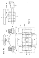
- Fig. 2 is a side elevation, wherein the female strips 3 and the counter strips 4 are shown in section.
- the operation of the fastening elements 5 for the counter strips is briefly explained with the aid of the illustration in FIG. 2.
- the fasteners are made of rubber-elastic material and are connected by the pins 13 to the longitudinal frames of the frame 2 of the slatted frame. In the longitudinal frames and also in the fastening element 5, bores or openings are provided for inserting the pins 13.
- the bearing sleeve 11 with the stop ribs 11a is located on the obtuse-angled tip of the fastening element designed as a triangle.
- this fastening element enables suspension in the vertical direction and also resilient rotation of the spring strips 3 about their longitudinal axis. This rotation is caused by the stop of the stop rib 11a on the triangular part of the fastening limited element.
- the spring action in the vertical direction comes about because, on the one hand, the part designed as a leg of the triangle is compressed and, on the other hand, the part representing the base line between the two pins 13 is expanded. This expansion is due to the fact that the compression of the triangle at both acute angles, which are fastened by means of the pins 13, causes a slight rotation.
- fasteners 6 are also shown with the bearing sleeves 12 for the counter strips 4.
- fastening element 6 Due to its adapted shape with the lateral recesses, which are adapted to the fastening element 5, one fastening element 6 can be inserted between two fastening elements 5. Due to the rubber elasticity of the fastening element 5, the fixed fastening element 6 is held without further fastening means. While the entire fastening element 5 for the female connectors is made of rubber-elastic material, the fastening element 6 consists of essentially solid plastic material.
- Fig. 3 the arrangement shown in Fig. 2 is shown from above.
- the manner of fastening the fastening elements 5 for the female connectors can be seen. This is done by the special bolt 13, which is inserted into a hole in the frame of the frame and in a corresponding opening in the fastener.
- the bearing sleeves 11 and 12 for the female connectors 3 and the counter strips 4 are also visible.
- the same arrangement is shown in perspective in FIG. 4, the buffer elements 15 also being visible.
- the distance between the positions of the counter strips 4 and the female strips 3 is clearly visible here. This relatively large distance of 4 - 6 cm ensures good ventilation of the mattress even in ver adjustable area of the slatted frame.
- the buffer elements according to this illustration are inserted between two counter strips and are guided through the grooves 18.
- the base 17 of the buffer element is made of a hard material, while the buffer zone 16 is made of a rubber-elastic material.
- the distance between the uppermost part of the buffer zone 16 and the spring strip above it is approximately 1 cm.
- the adjustable hardness only comes into play after the female connector has lowered by at least 1 cm due to load.
- the scales 7 are attached to the counter strips 4, the pointer 8 of the buffer element 15 pointing to the corresponding hardness value.
- the pointer 8 of the buffer element 15 can also be designed as a handle for moving. (Not shown in Fig. 4).
- FIG. 5 shows an illustration similar to FIG. 4, but an alternative buffer element 19 is shown here.
- This has the two lateral arms 20 on which the rubber-elastic buffer zones 21 are located. These buffer zones of a single element come to rest under two adjacent female connectors 3. As a result, two female connectors are additionally supported by a counter bar.
- a scale 7 is also applied to the counter bar 4, which can be read through the window 23 of the buffer element. The buffer element is pushed over the opening 22 onto the counter bar.
- FIG. 6 shows in particular the cutouts 24 which are on the rounded ends of the fastening means 5 for the female connectors.
- FIG. 6 shows the end face of the fastening element 6
- FIG. 7 shows a top view
- FIG. 8 shows a side view.
- the bearing sleeve 12 has ribs 12a and 12b, which serve to ensure that the inserted counter strip sits snugly.
- Fig. 9 the same fastener 6 is shown in perspective. in particular the position of the cutouts 24 is visible. These recesses are adapted to the shape of the rubber-elastic fastening elements for the female connectors in the plug-on area.
- FIGS. 10 and 11 represent three views of a buffer element 15.
- FIGS. 10 and 11 are each a side view and FIG. 12 is a view from above.
- 10 also shows a special embodiment of the groove 18. It is in fact necessary that the buffer elements are designed in such a way that they cannot be inadvertently moved from the set position.
- the part 8a projecting over the counter strips is provided with handles for better displacement.
- 10 and 11 the distance h between the rubber-elastic buffer zone and the female connector 3 is also shown.
- the middle part of the buffer element is covered by the spring strip 3, while the parts 8a protrude under this spring strip on both sides.
- Part 8a also serves as a handle for moving the buffer element and can be provided with a part for alignment with the scale.
- each buffer element supports two female connectors. It is therefore possible that in the hardness-adjustable zone of the slatted frame only every second space between the slats is fitted with a counter bar. In such an embodiment of the slatted frame according to the invention, the maximum adjustable hardness would consequently be somewhat lower than if all the spaces in the hardness-adjustable zone are provided with corresponding buffer elements by counter strips. If this is the case, each supported female connector, with the exception of that at the edge of the adjustable zone, is supported by two adjacent buffer elements. This means that if, as is normally the case, each counter bar has two buffer elements, each female bar would be supported by four points.
Landscapes
- Mattresses And Other Support Structures For Chairs And Beds (AREA)
- Chairs For Special Purposes, Such As Reclining Chairs (AREA)
Priority Applications (1)
| Application Number | Priority Date | Filing Date | Title |
|---|---|---|---|
| AT89810354T ATE91067T1 (de) | 1988-05-19 | 1989-05-16 | Lattenrost fuer liegemoebel. |
Applications Claiming Priority (2)
| Application Number | Priority Date | Filing Date | Title |
|---|---|---|---|
| CH1912/88 | 1988-05-19 | ||
| CH191288 | 1988-05-19 |
Publications (2)
| Publication Number | Publication Date |
|---|---|
| EP0344105A1 true EP0344105A1 (fr) | 1989-11-29 |
| EP0344105B1 EP0344105B1 (fr) | 1993-06-30 |
Family
ID=4221502
Family Applications (1)
| Application Number | Title | Priority Date | Filing Date |
|---|---|---|---|
| EP89810354A Expired - Lifetime EP0344105B1 (fr) | 1988-05-19 | 1989-05-16 | Assemblage de lattes pour un sommier |
Country Status (3)
| Country | Link |
|---|---|
| EP (1) | EP0344105B1 (fr) |
| AT (1) | ATE91067T1 (fr) |
| DE (1) | DE58904832D1 (fr) |
Cited By (4)
| Publication number | Priority date | Publication date | Assignee | Title |
|---|---|---|---|---|
| AU637628B2 (en) * | 1990-06-08 | 1993-06-03 | Silent Night Pty. Ltd. | Mattress inner assembly and mattress |
| FR2688393A1 (fr) * | 1992-03-11 | 1993-09-17 | Murrate Pierre | Sommier a lames. |
| FR2890839A1 (fr) * | 2005-09-22 | 2007-03-23 | Oniris Soc Par Actions Simplif | Dispositif de suspension pour sommier a curseur mobile |
| EP4533980A1 (fr) * | 2023-10-04 | 2025-04-09 | ADA Möbelfabrik GmbH | Sommier à lattes |
Families Citing this family (1)
| Publication number | Priority date | Publication date | Assignee | Title |
|---|---|---|---|---|
| US11618567B2 (en) | 2020-05-18 | 2023-04-04 | B/E Aerospace, Inc. | Slat construction of full-time berth for use in aerospace applications |
Citations (3)
| Publication number | Priority date | Publication date | Assignee | Title |
|---|---|---|---|---|
| GB2005134A (en) * | 1977-09-30 | 1979-04-19 | Marpal Ag | Under-mattress for beds or similar articles of furniture |
| EP0050293A2 (fr) * | 1980-10-21 | 1982-04-28 | Marpal AG | Dispositif pour renforcer de manière variable et en différents endroits les sommiers à lattes des meubles de couchage |
| DE8708160U1 (de) * | 1987-06-10 | 1987-07-23 | Rössle & Wanner GmbH, 7403 Ammerbuch | Federleistenelement für einen Lattenrost |
-
1989
- 1989-05-16 DE DE8989810354T patent/DE58904832D1/de not_active Expired - Fee Related
- 1989-05-16 AT AT89810354T patent/ATE91067T1/de not_active IP Right Cessation
- 1989-05-16 EP EP89810354A patent/EP0344105B1/fr not_active Expired - Lifetime
Patent Citations (3)
| Publication number | Priority date | Publication date | Assignee | Title |
|---|---|---|---|---|
| GB2005134A (en) * | 1977-09-30 | 1979-04-19 | Marpal Ag | Under-mattress for beds or similar articles of furniture |
| EP0050293A2 (fr) * | 1980-10-21 | 1982-04-28 | Marpal AG | Dispositif pour renforcer de manière variable et en différents endroits les sommiers à lattes des meubles de couchage |
| DE8708160U1 (de) * | 1987-06-10 | 1987-07-23 | Rössle & Wanner GmbH, 7403 Ammerbuch | Federleistenelement für einen Lattenrost |
Cited By (4)
| Publication number | Priority date | Publication date | Assignee | Title |
|---|---|---|---|---|
| AU637628B2 (en) * | 1990-06-08 | 1993-06-03 | Silent Night Pty. Ltd. | Mattress inner assembly and mattress |
| FR2688393A1 (fr) * | 1992-03-11 | 1993-09-17 | Murrate Pierre | Sommier a lames. |
| FR2890839A1 (fr) * | 2005-09-22 | 2007-03-23 | Oniris Soc Par Actions Simplif | Dispositif de suspension pour sommier a curseur mobile |
| EP4533980A1 (fr) * | 2023-10-04 | 2025-04-09 | ADA Möbelfabrik GmbH | Sommier à lattes |
Also Published As
| Publication number | Publication date |
|---|---|
| EP0344105B1 (fr) | 1993-06-30 |
| DE58904832D1 (de) | 1993-08-05 |
| ATE91067T1 (de) | 1993-07-15 |
Similar Documents
| Publication | Publication Date | Title |
|---|---|---|
| EP0006840B1 (fr) | Support élastique flexible | |
| CH619605A5 (fr) | ||
| EP0150873B1 (fr) | Sommier | |
| EP3045083B1 (fr) | Sommiers à lattes dote d'un cadre et d'un dispositif de mesure | |
| DE60210992T2 (de) | Vorrichtung zur Befestigung einer Federleiste an den Rahmen eines Lattenrosts | |
| EP0710459A1 (fr) | Sommier à lattes pour lit | |
| EP1155643B1 (fr) | Dispositif de support | |
| DE102015100703A1 (de) | Lattenrost | |
| AT390722B (de) | Einsatz fuer ein liegemoebel | |
| EP0344105B1 (fr) | Assemblage de lattes pour un sommier | |
| DE9312069U1 (de) | Liegefläche | |
| DE29907850U1 (de) | Lattenrost | |
| DE3815098C2 (de) | Bettrost | |
| EP0397069A1 (fr) | Sommier à lattes avec des lattes intermédiaires supportées élastiquement | |
| EP0539644B1 (fr) | Sommier à lattes | |
| DE102008059733B4 (de) | Krankenhausbett mit abnehmbarer Kopfendplatte | |
| EP0141260B1 (fr) | Sommier à lattes pour lits | |
| EP2322060B1 (fr) | Système de matelas pour lit | |
| EP0194538B1 (fr) | Sommier à lattes | |
| DE202015106024U1 (de) | Federleiste für eine Matratzenunterfederung sowie Matratzenunterfederungen mit zumindest einer solchen Federleiste | |
| EP3066960B1 (fr) | Latte élastique pour un sommier et sommier comprenant au moins une telle latte élastique | |
| EP3069634B1 (fr) | Latte pour suspension a ressort equipant un siege ou un lit | |
| EP3170428B1 (fr) | Module de ressort à lamelles et système de suspension comprenant de tels modules | |
| DE8809806U1 (de) | Federndes Bauelement zur Ausbildung einer Liegefläche eines Liegemöbels | |
| DE19726793C1 (de) | Bettlattenrost mit Härtezoneneinstellung |
Legal Events
| Date | Code | Title | Description |
|---|---|---|---|
| PUAI | Public reference made under article 153(3) epc to a published international application that has entered the european phase |
Free format text: ORIGINAL CODE: 0009012 |
|
| AK | Designated contracting states |
Kind code of ref document: A1 Designated state(s): AT BE CH DE ES FR GB IT LI NL |
|
| 17P | Request for examination filed |
Effective date: 19900209 |
|
| 17Q | First examination report despatched |
Effective date: 19920304 |
|
| GRAA | (expected) grant |
Free format text: ORIGINAL CODE: 0009210 |
|
| AK | Designated contracting states |
Kind code of ref document: B1 Designated state(s): AT BE CH DE ES FR GB IT LI NL |
|
| PG25 | Lapsed in a contracting state [announced via postgrant information from national office to epo] |
Ref country code: IT Free format text: LAPSE BECAUSE OF FAILURE TO SUBMIT A TRANSLATION OF THE DESCRIPTION OR TO PAY THE FEE WITHIN THE PRESCRIBED TIME-LIMIT;WARNING: LAPSES OF ITALIAN PATENTS WITH EFFECTIVE DATE BEFORE 2007 MAY HAVE OCCURRED AT ANY TIME BEFORE 2007. THE CORRECT EFFECTIVE DATE MAY BE DIFFERENT FROM THE ONE RECORDED. Effective date: 19930630 Ref country code: ES Free format text: THE PATENT HAS BEEN ANNULLED BY A DECISION OF A NATIONAL AUTHORITY Effective date: 19930630 Ref country code: GB Effective date: 19930630 Ref country code: NL Effective date: 19930630 Ref country code: BE Effective date: 19930630 |
|
| REF | Corresponds to: |
Ref document number: 91067 Country of ref document: AT Date of ref document: 19930715 Kind code of ref document: T |
|
| REF | Corresponds to: |
Ref document number: 58904832 Country of ref document: DE Date of ref document: 19930805 |
|
| ET | Fr: translation filed | ||
| NLV1 | Nl: lapsed or annulled due to failure to fulfill the requirements of art. 29p and 29m of the patents act | ||
| GBV | Gb: ep patent (uk) treated as always having been void in accordance with gb section 77(7)/1977 [no translation filed] |
Effective date: 19930630 |
|
| PLBE | No opposition filed within time limit |
Free format text: ORIGINAL CODE: 0009261 |
|
| STAA | Information on the status of an ep patent application or granted ep patent |
Free format text: STATUS: NO OPPOSITION FILED WITHIN TIME LIMIT |
|
| PG25 | Lapsed in a contracting state [announced via postgrant information from national office to epo] |
Ref country code: AT Effective date: 19940516 |
|
| 26N | No opposition filed | ||
| PGFP | Annual fee paid to national office [announced via postgrant information from national office to epo] |
Ref country code: FR Payment date: 19950410 Year of fee payment: 7 |
|
| PGFP | Annual fee paid to national office [announced via postgrant information from national office to epo] |
Ref country code: DE Payment date: 19950421 Year of fee payment: 7 |
|
| PGFP | Annual fee paid to national office [announced via postgrant information from national office to epo] |
Ref country code: CH Payment date: 19950518 Year of fee payment: 7 |
|
| PG25 | Lapsed in a contracting state [announced via postgrant information from national office to epo] |
Ref country code: CH Effective date: 19960531 Ref country code: LI Effective date: 19960531 |
|
| REG | Reference to a national code |
Ref country code: CH Ref legal event code: PL |
|
| PG25 | Lapsed in a contracting state [announced via postgrant information from national office to epo] |
Ref country code: FR Effective date: 19970131 |
|
| PG25 | Lapsed in a contracting state [announced via postgrant information from national office to epo] |
Ref country code: DE Effective date: 19970201 |
|
| REG | Reference to a national code |
Ref country code: FR Ref legal event code: ST |