EP0344410A2 - Calandre à fente réglable pour masses céramiques - Google Patents
Calandre à fente réglable pour masses céramiques Download PDFInfo
- Publication number
- EP0344410A2 EP0344410A2 EP89103998A EP89103998A EP0344410A2 EP 0344410 A2 EP0344410 A2 EP 0344410A2 EP 89103998 A EP89103998 A EP 89103998A EP 89103998 A EP89103998 A EP 89103998A EP 0344410 A2 EP0344410 A2 EP 0344410A2
- Authority
- EP
- European Patent Office
- Prior art keywords
- adjustable
- rolling mill
- roll
- rockers
- bearing
- Prior art date
- Legal status (The legal status is an assumption and is not a legal conclusion. Google has not performed a legal analysis and makes no representation as to the accuracy of the status listed.)
- Withdrawn
Links
Images
Classifications
-
- B—PERFORMING OPERATIONS; TRANSPORTING
- B30—PRESSES
- B30B—PRESSES IN GENERAL
- B30B15/00—Details of, or accessories for, presses; Auxiliary measures in connection with pressing
- B30B15/04—Frames; Guides
-
- B—PERFORMING OPERATIONS; TRANSPORTING
- B28—WORKING CEMENT, CLAY, OR STONE
- B28B—SHAPING CLAY OR OTHER CERAMIC COMPOSITIONS; SHAPING SLAG; SHAPING MIXTURES CONTAINING CEMENTITIOUS MATERIAL, e.g. PLASTER
- B28B3/00—Producing shaped articles from the material by using presses; Presses specially adapted therefor
- B28B3/12—Producing shaped articles from the material by using presses; Presses specially adapted therefor wherein one or more rollers exert pressure on the material
- B28B3/126—Producing shaped articles from the material by using presses; Presses specially adapted therefor wherein one or more rollers exert pressure on the material on material passing directly between the co-operating rollers
-
- B—PERFORMING OPERATIONS; TRANSPORTING
- B30—PRESSES
- B30B—PRESSES IN GENERAL
- B30B3/00—Presses characterised by the use of rotary pressing members, e.g. rollers, rings, discs
- B30B3/04—Presses characterised by the use of rotary pressing members, e.g. rollers, rings, discs co-operating with one another, e.g. with co-operating cones
Definitions
- the invention relates to a rolling mill with an adjustable nip for ceramic masses according to the preamble of claim 1.
- Such rolling mills have been known and used for many years.
- a problem with such rolling mills is the exact setting and fixing of the roll gap. As a result of uneven wear of the roller surfaces and possible non-parallel turning of the rollers when the roller surfaces have to be smoothed, it is hardly possible to maintain a constant nip across the entire width of the rollers in previous rolling mills. Furthermore, in the conventional rolling mills, an adjustment or fixation of the roll gap, generally using spacers to be inserted or exchanged by hand, can only take place when the rolling mill is at a standstill.
- the object of the present invention is therefore to design the known rolling mills in such a way that an exact setting and fixing of the nip is possible over the entire width of the roller, in a simple and quick manner and also when the rolling mill is running.
- the solution to this problem results from the characterizing features of patent claim 1.
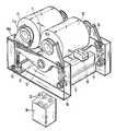
- 10 denotes a machine stand on which the two rolling mill rollers 11 and 12 are mounted.
- the axis 11a of the roller 11 is mounted directly in lugs 10a of the machine stand 10 on both sides: this roller is therefore referred to as the fixed roller.
- the axis 12a of the In contrast, roller 12 is supported on both sides on rockers 14 which can be pivoted relative to the machine stand 10; the roller 12 is therefore referred to as an adjusting roller.
- the rockers 14 in turn are pivotally mounted on stub axles 15 of the machine stand 10 and are designed in the manner of a two-arm lever.
- the free end of one lever arm is supported by a spindle lifting element 16, the free end of the other lever arm by a hydraulic piston-cylinder unit 17.
- the axis 12a of the adjusting roller 12 is also mounted on the rockers.
- a lathe movable on the machine stand 10 is indicated for turning off the adjusting roller 12.
- 19 designates a hydraulic unit with pumps, display elements and control buttons 20.
- the rockers 14 are loaded by the piston-cylinder units 17 in the upward direction, with a hydraulic pressure predetermined by the hydraulic unit 19.
- the height of the spindle lifting elements 16 can be adjusted separately, either manually or by motor.
- the height of the elements 16 defines the width of the roll gap a, the gap being wider the higher the elements 16 are set. Because the two spindle lifting elements 16 are separately adjustable, the parallelism of the roller gap a over the entire roller width b can also be ensured if, for example, one of the rollers has been turned non-parallel, for example the roller 12 by the lathe 18.
- the hydraulic pressure in the piston-cylinder units 17 is dimensioned such that, in normal operation, the rockers 14 are pressed firmly against the spindle lifting elements 16, but when a hard foreign body penetrates into the roll gap, the back pressure caused by this foreign body overcomes the hydraulic pressure of the elements 17 , with the result of an opening of the roller gap (protection of the hard roller surface). As soon as the stranger the body has "failed" downwards, the nip closes again automatically to its set value.
- the adjustment of the roll gap can obviously be carried out manually or by motor without having to stop the rolling mill.
Landscapes
- Engineering & Computer Science (AREA)
- Mechanical Engineering (AREA)
- Manufacturing & Machinery (AREA)
- Chemical & Material Sciences (AREA)
- Ceramic Engineering (AREA)
- Crushing And Grinding (AREA)
- Rolls And Other Rotary Bodies (AREA)
- Reduction Rolling/Reduction Stand/Operation Of Reduction Machine (AREA)
Applications Claiming Priority (2)
| Application Number | Priority Date | Filing Date | Title |
|---|---|---|---|
| DE19883818540 DE3818540A1 (de) | 1988-05-31 | 1988-05-31 | Walzwerk mit verstellbarem walzenspalt fuer keramische massen |
| DE3818540 | 1988-05-31 |
Publications (2)
| Publication Number | Publication Date |
|---|---|
| EP0344410A2 true EP0344410A2 (fr) | 1989-12-06 |
| EP0344410A3 EP0344410A3 (fr) | 1991-04-17 |
Family
ID=6355542
Family Applications (1)
| Application Number | Title | Priority Date | Filing Date |
|---|---|---|---|
| EP19890103998 Withdrawn EP0344410A3 (fr) | 1988-05-31 | 1989-03-07 | Calandre à fente réglable pour masses céramiques |
Country Status (2)
| Country | Link |
|---|---|
| EP (1) | EP0344410A3 (fr) |
| DE (1) | DE3818540A1 (fr) |
Cited By (2)
| Publication number | Priority date | Publication date | Assignee | Title |
|---|---|---|---|---|
| DE4435935A1 (de) * | 1994-10-07 | 1996-04-11 | Rieter Werke Haendle | Verfahren zum Einstellen des Walzenspaltes eines Walzwerks und Walzwerk |
| WO2014116157A1 (fr) * | 2013-01-28 | 2014-07-31 | Oneday Wall Ab | Machine et procédé de production de panneau de construction |
Families Citing this family (5)
| Publication number | Priority date | Publication date | Assignee | Title |
|---|---|---|---|---|
| DE4121882A1 (de) * | 1991-07-02 | 1993-01-28 | Neumann Bruno Dipl Ing | Walzwerk fuer keramische massen |
| AU2021208299B9 (en) * | 2020-01-14 | 2023-07-27 | Thyssenkrupp Ag | Device and method for milling input material |
| BE1027984B1 (de) * | 2020-01-14 | 2021-08-16 | Thyssenkrupp Ind Solutions Ag | Vorrichtung und Verfahren zum Mahlen von Einsatzmaterial sowie Steuerungs-/Regelungseinrichtung und Verwendung |
| BE1027987B1 (de) * | 2020-01-14 | 2021-08-16 | Thyssenkrupp Ag | Vorrichtung und Verfahren zum Mahlen von Einsatzmaterial sowie Steuerungs-/Regelungseinrichtung und Verwendung |
| BE1027983B1 (de) * | 2020-01-14 | 2021-08-16 | Thyssenkrupp Ag | Vorrichtung und Verfahren zum Mahlen von Einsatzmaterial sowie Steuerungs-/Regelungseinrichtung und Verwendung |
Family Cites Families (10)
| Publication number | Priority date | Publication date | Assignee | Title |
|---|---|---|---|---|
| DE1004458B (de) * | 1953-06-09 | 1957-03-14 | Koppers Gmbh Heinrich | Walzenmuehle |
| DE28476C (de) * | 1965-04-30 | H. bauermeister in Hamburg | Vorrichtung zum Verstellen der Walzen von Walzenstühlen während des Betriebes | |
| DE2045740A1 (de) * | 1970-09-16 | 1972-03-23 | J.M. Voith GmbH Maschinenfabrik, 7920 Heidenheim | Vorrichtung zum genauen parallelen Aneinanderlegen zweier langer Maschinenteile, insbesondere Preßwalzen |
| IT1057622B (it) * | 1976-02-25 | 1982-03-30 | Morando Spa Off | Laminatoio per argilla e simili |
| DE2704243A1 (de) * | 1977-02-02 | 1978-08-03 | Kloeckner Humboldt Deutz Ag | Walzenmuehle |
| DE2744990C3 (de) * | 1977-10-06 | 1980-07-17 | Kuesters, Eduard, 4150 Krefeld | Kalander zur Druckbehandlung von Bahnen |
| IT1147385B (it) * | 1981-07-16 | 1986-11-19 | Giacomo Ferrero | Cilindraia o mulino a cilindri a regolazione e sicurezza idrauliche |
| DE3308417A1 (de) * | 1982-03-20 | 1983-09-22 | Henry Simon Ltd., Stockport, Cheshire | Walzenmuehle |
| US4519757A (en) * | 1984-01-17 | 1985-05-28 | Magna-Graphics Corporation | Web surface treating apparatus |
| US4810179A (en) * | 1988-01-27 | 1989-03-07 | Marshall & Williams Company | Force indicator for casting machines |
-
1988
- 1988-05-31 DE DE19883818540 patent/DE3818540A1/de not_active Withdrawn
-
1989
- 1989-03-07 EP EP19890103998 patent/EP0344410A3/fr not_active Withdrawn
Cited By (6)
| Publication number | Priority date | Publication date | Assignee | Title |
|---|---|---|---|---|
| DE4435935A1 (de) * | 1994-10-07 | 1996-04-11 | Rieter Werke Haendle | Verfahren zum Einstellen des Walzenspaltes eines Walzwerks und Walzwerk |
| DE4435935C3 (de) * | 1994-10-07 | 2003-11-06 | Rieter Werke Haendle | Verfahren zum Einstellen des Walzenspaltes eines Walzwerks und Walzwerk |
| WO2014116157A1 (fr) * | 2013-01-28 | 2014-07-31 | Oneday Wall Ab | Machine et procédé de production de panneau de construction |
| US9694566B2 (en) | 2013-01-28 | 2017-07-04 | Oneday Wall Ab | Machine and manufacturing method for building board |
| RU2637677C2 (ru) * | 2013-01-28 | 2017-12-06 | Уандей Уолл Аб | Машина и способ изготовления строительной панели |
| US10189234B2 (en) | 2013-01-28 | 2019-01-29 | Oneday Wall Ab | Machine and manufacturing method for building board |
Also Published As
| Publication number | Publication date |
|---|---|
| DE3818540A1 (de) | 1989-12-07 |
| EP0344410A3 (fr) | 1991-04-17 |
Similar Documents
| Publication | Publication Date | Title |
|---|---|---|
| DE2760350C2 (fr) | ||
| DE2912458C2 (fr) | ||
| DE29902366U1 (de) | Schaumschwamm-Schneidemaschine mit senkrechtem Schneiddraht | |
| DE69315337T2 (de) | Maschine zum schneiden von bogen aus einer papierbahn und zum gleichzeitigen schneiden eines querstreifens | |
| EP0252418A1 (fr) | Guillotine | |
| DE3207622A1 (de) | Vorrichtung zum an-, ab- und einstellen von auftragwalzen am plattenzylinder von druckmaschinen | |
| DE1950555B2 (de) | Vorrichtung zum Behandeln, insbesondere Beschichten von bahnförmigem Material in einem einstellbaren Walzenspalt | |
| EP0386520A2 (fr) | Broyeur à cylindres à lit de matière | |
| DE2948842C2 (de) | Vorziehpartie | |
| DE3016785C2 (de) | Hydraulisches Mehrwalzwerk | |
| DE3818540A1 (de) | Walzwerk mit verstellbarem walzenspalt fuer keramische massen | |
| EP0255714A2 (fr) | Laminoir à cylindres multiples avec des cylindres intermédiaires déplaçables axialement et aux extrémités coniques | |
| DE899464C (de) | Streckwerk fuer Vor- und Feinspinnmaschinen | |
| DE2127757B2 (de) | Fehlbogen-Abtast- und Steuervorrichtung | |
| DE1602184B2 (de) | Vielwalzen-Gerüstanordnung | |
| DE2932115A1 (de) | Richtmaschine | |
| DE3012852C2 (de) | Superkalander | |
| DE633933C (de) | Stelleinrichtung an Walzenmuehlen fuer pastenartiges Gut | |
| DE226327C (fr) | ||
| DE3048280A1 (de) | "walzgeruest" | |
| DE340045C (de) | Schrot-, Mahl- und Quetschmuehle | |
| DE1234661B (de) | Walzenrichtmaschine zum Richten von Metallplatten und -baendern | |
| DE234046C (fr) | ||
| DE476271C (de) | Vorrichtung zum Auswechseln der Papierrollen bei Druckmaschinen, insbesondere Rotationsdruckmaschinen | |
| DE3308417A1 (de) | Walzenmuehle |
Legal Events
| Date | Code | Title | Description |
|---|---|---|---|
| PUAI | Public reference made under article 153(3) epc to a published international application that has entered the european phase |
Free format text: ORIGINAL CODE: 0009012 |
|
| AK | Designated contracting states |
Kind code of ref document: A2 Designated state(s): DE ES FR GB IT |
|
| PUAL | Search report despatched |
Free format text: ORIGINAL CODE: 0009013 |
|
| AK | Designated contracting states |
Kind code of ref document: A3 Designated state(s): DE ES FR GB IT |
|
| 17P | Request for examination filed |
Effective date: 19910523 |
|
| 17Q | First examination report despatched |
Effective date: 19911004 |
|
| STAA | Information on the status of an ep patent application or granted ep patent |
Free format text: STATUS: THE APPLICATION HAS BEEN WITHDRAWN |
|
| 18W | Application withdrawn |
Withdrawal date: 19920717 |