EP0255714A2 - Laminoir à cylindres multiples avec des cylindres intermédiaires déplaçables axialement et aux extrémités coniques - Google Patents
Laminoir à cylindres multiples avec des cylindres intermédiaires déplaçables axialement et aux extrémités coniques Download PDFInfo
- Publication number
- EP0255714A2 EP0255714A2 EP87111242A EP87111242A EP0255714A2 EP 0255714 A2 EP0255714 A2 EP 0255714A2 EP 87111242 A EP87111242 A EP 87111242A EP 87111242 A EP87111242 A EP 87111242A EP 0255714 A2 EP0255714 A2 EP 0255714A2
- Authority
- EP
- European Patent Office
- Prior art keywords
- roll
- roller
- rolls
- bale
- tapered
- Prior art date
- Legal status (The legal status is an assumption and is not a legal conclusion. Google has not performed a legal analysis and makes no representation as to the accuracy of the status listed.)
- Granted
Links
Images

Classifications
-
- B—PERFORMING OPERATIONS; TRANSPORTING
- B21—MECHANICAL METAL-WORKING WITHOUT ESSENTIALLY REMOVING MATERIAL; PUNCHING METAL
- B21B—ROLLING OF METAL
- B21B13/00—Metal-rolling stands, i.e. an assembly composed of a stand frame, rolls, and accessories
- B21B13/14—Metal-rolling stands, i.e. an assembly composed of a stand frame, rolls, and accessories having counter-pressure devices acting on rolls to inhibit deflection of same under load; Back-up rolls
- B21B13/147—Cluster mills, e.g. Sendzimir mills, Rohn mills, i.e. each work roll being supported by two rolls only arranged symmetrically with respect to the plane passing through the working rolls
-
- B—PERFORMING OPERATIONS; TRANSPORTING
- B21—MECHANICAL METAL-WORKING WITHOUT ESSENTIALLY REMOVING MATERIAL; PUNCHING METAL
- B21B—ROLLING OF METAL
- B21B27/00—Rolls, roll alloys or roll fabrication; Lubricating, cooling or heating rolls while in use
- B21B27/02—Shape or construction of rolls
- B21B27/021—Rolls for sheets or strips
- B21B2027/022—Rolls having tapered ends
-
- B—PERFORMING OPERATIONS; TRANSPORTING
- B21—MECHANICAL METAL-WORKING WITHOUT ESSENTIALLY REMOVING MATERIAL; PUNCHING METAL
- B21B—ROLLING OF METAL
- B21B2269/00—Roll bending or shifting
- B21B2269/12—Axial shifting the rolls
- B21B2269/16—Intermediate rolls
Definitions
- the invention relates to a multi-roll mill stand, the two work rolls of which are each supported directly or indirectly by a pair of axially adjustable intermediate rolls on support rolls or support rolls arranged in series, each intermediate roll having only one tapered roll end and two tapered roll end ends on each side of the Lying rolled up.
- a known countermeasure in multi-roll stands in which the direct bending of the work or intermediate rolls known from other stands is not possible for structural reasons, is that Work rolls are not to be supported over their entire length via intermediate rolls, but only over a partial length, the partial length being adjustable.
- each work roll is supported on a pair of intermediate rolls.
- the intermediate rolls are in the same way tapered at one end, parabolic or otherwise, the tapered roll barrel ends of the intermediate rolls assigned to the different work rolls lying on opposite sides of the roll stand, while the tapered roll roll ends of the intermediate rolls assigned to the same work roll lie on the same side of the roll stand .
- the support length can be adjusted as a function of the width of the strip to be rolled by axially displacing one pair of intermediate rolls and / or both pairs of intermediate rolls such that each rolled strip edge overlaps the tapered ends to a greater or lesser extent.
- Such a multi-roll mill stand has proven itself in practice for many years; Nevertheless, the setting options for influencing the roll gap profile on such multi-roll rolling stands are sufficient, namely the pairwise axial displacement of the intermediate rolls with tapered roll barrel ends and the presetting of the bending line on two support rolls to achieve this Today's demands on the flatness of the band are often not sufficient.
- the prior art also includes duo, quarto or six-high roll stands (EP 0 049 798 A2), the axially displaceable intermediate or work rolls of which have oppositely arranged, curved contours over the entire length of the bale, which are seamless in a certain axial position of the intermediate rolls complete.
- Roll stands, the intermediate or work rolls of which have contoured roll bales, are intended to enable a uniform, continuous change in the roll gap profile over the entire length of the roll gap, the rolling strip in the edge region being influenced by the known method of roll bending possible here.
- the invention has for its object to provide a multi-roll mill stand of the type mentioned, in which the support of the work rolls, in particular in the edge regions of the rolled strip, is adjustable to a greater extent than previously.
- the support curve for the work rolls not only includes the axial offset of the tapered roll bale ends, but also their contour, the roll bale ends assigned to the same band edge can have different tapering contours.
- the support curve for the work rolls be influenced with independently axially adjustable intermediate rolls, but also in the area between the edge areas if, according to a further embodiment of the invention, an intermediate roll of each intermediate roll pair has a contour deviating from the cylindrical shape between the roller bale ends. Since the shape of the roll gap resulting from the rolling force results from the addition of the local diameter of the contoured intermediate rolls touching the work rolls at the same point, it is easily possible for the skilled worker in practice to choose the suitable dimensioning of the contour for the respective purpose.
- each lockable intermediate roller is supported on the support rollers or the support rollers by at least one additional intermediate roller with contoured roller balls.
- this configuration comparable effects can be achieved as with contoured roll bales for the intermediate rolls which directly support the work rolls.
- each intermediate roller is arranged asymmetrically with respect to the center of the roller bale.
- the two intermediate rolls with their asymmetrically contoured roll bales should be arranged in opposite directions. With such an arrangement, a relative axial displacement of the two intermediate rolls results in an increase or decrease in the curvature of the roll gap profile in the central region.
- the asymmetrical contouring of the intermediate rolls is particularly suitable for multi-roll stands in which it is not possible to position the support line on the support rolls, for example when the support rolls are solid.
- Intermediate rolls with contoured roll bales can also be used with multi-roll stands, which offer the conventional setting option for back-up rolls.
- the effect of the axially displaceable intermediate rolls with the contoured roll bales influencing the roll gap comes into play when a Rolling program is run, in which the rolling forces are so low that the intermediate rollers and the axes of the support rollers are not deformed so much that the support saddles of the support rollers can be fully supported on the preset supports.
- this embodiment of the invention is suitable for the stepless adjustment of the roll gap profile when dressing or re-rolling strips to a certain strength.
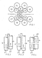
- each work roll 1, 2 is supported on four support rolls 13 to 20 via a pair of intermediate rolls 3 to 6 and three further intermediate rolls 7 to 12.
- the roll bales of each parse of the intermediate rolls 3 to 6 are each tapered conically or parabolically at only one end of the bale. However, other taper contours are also possible.
- the roll barrel ends 21, 22 have the same conical shape.
- the arrangement is such that the intermediate rolls 3, 4 assigned to the work roll 1, with their conical roll end ends 21, 22, lie on one side of the roll stand and thus also on one edge of the rolled strip, while the intermediate rolls 5, assigned to the other work roll 2 6 with their likewise conical roller bale ends on the other side of the roll stand and thus also on the other edge of the rolled strip.
- the embodiment of Figure 3 differs from that of Figure 2 only in that the roll barrel ends 23, 24 have a different contour.
- the roll bale ends 25, 26 of the conical roll bale ends 25, 26 assigned to the same work roll 1 are arranged on opposite sides of the roll stand.
- the intermediate rolls 3 to 6, whose conical roll bale ends are on the same side of the roll stand should expediently lie diagonally opposite one another in relation to the rolling stock plane.
- the intermediate rolls 3 to 6 which are located on the same roll stand side with their conical roll barrel ends 21 to 26 and therefore act on the same strip edge, are axially adjustable independently of one another, so that an axial offset, as in FIGS 4 is shown, can be adjusted.
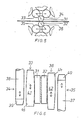
- the intermediate rolls 33, 34, 35, 36 assigned to each work roll 31, 32 are designed differently. While the intermediate rollers 34, 35, like the intermediate rollers of the exemplary embodiment in FIGS. 2 to 4, have a cylindrical roller bale 37, 38 with a conical roller bale end 39, 40, the roller bales 41, 42 of the two remaining intermediate rollers 33, 36 are contoured over their entire length.
- the contour of the roller bales 41, 42 is slightly parabolic, the largest diameter being outside the axial center. This asymmetry is in opposite directions in both roller bales 41, 42.
- This contour of the roller bales 41, 42 naturally includes at least one tapered roller bale end 43, 44.
- the roll profile in the strip center area can be more or less curved.
- the axial adjustment of the intermediate rollers 34 and 35 can be used to fine-tune the support curve at the strip edges.
- the further intermediate rolls 7-12 contoured roll bales can correspond to the roll bales 41, 42 of the intermediate rollers 33, 36 of the embodiment of FIGS. 5 and 6.
- either the intermediate rolls 8 and 11 or the intermediate rolls 7, 9 and 10, 12 have a contoured roll barrel.
- the intermediate rolls 3, 4 and 5, 6, which directly support the work rolls are supported on an intermediate roll 7-12 with a contoured roll barrel.
Landscapes
- Engineering & Computer Science (AREA)
- Mechanical Engineering (AREA)
- Reduction Rolling/Reduction Stand/Operation Of Reduction Machine (AREA)
- Metal Rolling (AREA)
- Heat Treatment Of Steel (AREA)
- Rollers For Roller Conveyors For Transfer (AREA)
Priority Applications (1)
| Application Number | Priority Date | Filing Date | Title |
|---|---|---|---|
| AT87111242T ATE75638T1 (de) | 1986-08-05 | 1987-08-04 | Vielwalzen-walzgeruest mit paarweise gegensinnig verschiebbaren, verjuengte enden aufweisenden zwischenwalzen. |
Applications Claiming Priority (4)
| Application Number | Priority Date | Filing Date | Title |
|---|---|---|---|
| DE3626516A DE3626516C1 (en) | 1986-08-05 | 1986-08-05 | Multi-roll rolling stand with intermediate rolls which have tapered ends and can be displaced in opposite directions in pairs |
| DE3626516 | 1986-08-05 | ||
| DE3720610 | 1987-06-23 | ||
| DE3720610A DE3720610C3 (de) | 1986-08-05 | 1987-06-23 | Vielwalzen-Walzgerüst mit paarweise gegensinnig verschiebbaren, verjüngte Enden aufweisenden Zwischenwalzen |
Publications (3)
| Publication Number | Publication Date |
|---|---|
| EP0255714A2 true EP0255714A2 (fr) | 1988-02-10 |
| EP0255714A3 EP0255714A3 (en) | 1990-01-17 |
| EP0255714B1 EP0255714B1 (fr) | 1992-05-06 |
Family
ID=25846256
Family Applications (1)
| Application Number | Title | Priority Date | Filing Date |
|---|---|---|---|
| EP87111242A Expired - Lifetime EP0255714B1 (fr) | 1986-08-05 | 1987-08-04 | Laminoir à cylindres multiples avec des cylindres intermédiaires déplaçables axialement et aux extrémités coniques |
Country Status (6)
| Country | Link |
|---|---|
| US (1) | US4805433A (fr) |
| EP (1) | EP0255714B1 (fr) |
| JP (1) | JPH069686B2 (fr) |
| CZ (1) | CZ277967B6 (fr) |
| ES (1) | ES2031478T3 (fr) |
| RU (1) | RU2011448C1 (fr) |
Cited By (2)
| Publication number | Priority date | Publication date | Assignee | Title |
|---|---|---|---|---|
| EP0401685A1 (fr) * | 1989-06-05 | 1990-12-12 | Kawasaki Steel Corporation | Cage de laminoir à rouleaux multiples |
| AU632719B2 (en) * | 1990-11-30 | 1993-01-07 | Kawasaki Steel Corporation | Method of controlling edge drop in cold rolling of steel |
Families Citing this family (8)
| Publication number | Priority date | Publication date | Assignee | Title |
|---|---|---|---|---|
| JPH07115048B2 (ja) * | 1988-10-19 | 1995-12-13 | 株式会社日立製作所 | 多段圧延機 |
| US5218852A (en) * | 1989-06-05 | 1993-06-15 | Kawasaki Steel Corporation | Multi-roll cluster rolling apparatus |
| DE4402398A1 (de) * | 1994-01-27 | 1995-08-10 | Froehling Josef Gmbh | Vielwalzengerüst in Ständerbauweise vorzugsweise mit direkter hydraulischer Anstellung |
| DE19713004C2 (de) * | 1997-03-27 | 2002-10-24 | Siemens Ag | Verfahren und Einrichtung zur Voreinstellung der Planheit eines Walzbandes |
| US5992202A (en) * | 1998-12-22 | 1999-11-30 | T. Sendzimir, Inc. | Drive system for axial adjustment of the first intermediate rolls of a 20-high rolling mill |
| FR2851942B1 (fr) * | 2003-03-05 | 2006-04-28 | Procede de changement de configuration d'un laminoir et laminoir perfectionne pour la mise en oeuvre du procede | |
| JP4847111B2 (ja) * | 2005-11-29 | 2011-12-28 | 株式会社日立製作所 | 多段式圧延機及び多段式圧延機の制御方法 |
| AT509107B1 (de) * | 2009-12-10 | 2011-09-15 | Siemens Vai Metals Tech Gmbh | Walzgerüst zur herstellung von walzband |
Family Cites Families (13)
| Publication number | Priority date | Publication date | Assignee | Title |
|---|---|---|---|---|
| US2566679A (en) * | 1943-02-25 | 1951-09-04 | Armzen Company | Rolling mill and lubrication method and means therefor |
| NL78648C (fr) * | 1948-06-10 | |||
| JPS5024902B2 (fr) * | 1972-01-28 | 1975-08-19 | ||
| US4270377A (en) * | 1978-05-19 | 1981-06-02 | T. Sendzimir, Inc. | Eighteen high rolling mill |
| JPS55123A (en) * | 1978-06-15 | 1980-01-05 | Matsushita Electric Works Ltd | Outer edge of electric razor and its preparation |
| DE2835514C2 (de) * | 1978-08-12 | 1982-12-02 | Sundwiger Eisenhütte Maschinenfabrik Grah & Co, 5870 Hemer | Vorrichtung zum axialen Verschieben von konischen Zwischenwalzen in einem Mehrrollen-Walzgerüst |
| DE3038865C1 (de) * | 1980-10-15 | 1982-12-23 | SMS Schloemann-Siemag AG, 4000 Düsseldorf | Walzgeruest mit axial verschiebbaren Walzen |
| US4519233A (en) * | 1980-10-15 | 1985-05-28 | Sms Schloemann-Siemag Ag | Roll stand with noncylindrical rolls |
| JPS5853311A (ja) * | 1981-09-24 | 1983-03-29 | Mitsubishi Heavy Ind Ltd | 多段クラスタ圧延機 |
| JPS5853310A (ja) * | 1981-09-24 | 1983-03-29 | Mitsubishi Heavy Ind Ltd | 多段クラスタ圧延機 |
| DE3221346C2 (de) * | 1982-06-05 | 1984-03-15 | Sundwiger Eisenhütte Maschinenfabrik Grah & Co, 5870 Hemer | Vielwalzen-Walzgerüst mit fliegenden, konischen Zwischenwalzen |
| JPS603902A (ja) * | 1983-06-22 | 1985-01-10 | Nisshin Steel Co Ltd | センジミアミルによる鋼帯の冷間圧延法 |
| US4656859A (en) * | 1985-08-21 | 1987-04-14 | Wean United, Inc. | Rolling mill stand employing variable crown rolls and associated method |
-
1987
- 1987-08-04 JP JP62193854A patent/JPH069686B2/ja not_active Expired - Fee Related
- 1987-08-04 ES ES198787111242T patent/ES2031478T3/es not_active Expired - Lifetime
- 1987-08-04 RU SU874203137A patent/RU2011448C1/ru active
- 1987-08-04 EP EP87111242A patent/EP0255714B1/fr not_active Expired - Lifetime
- 1987-08-05 US US07/081,992 patent/US4805433A/en not_active Expired - Lifetime
- 1987-08-05 CZ CS875828A patent/CZ277967B6/cs unknown
Cited By (2)
| Publication number | Priority date | Publication date | Assignee | Title |
|---|---|---|---|---|
| EP0401685A1 (fr) * | 1989-06-05 | 1990-12-12 | Kawasaki Steel Corporation | Cage de laminoir à rouleaux multiples |
| AU632719B2 (en) * | 1990-11-30 | 1993-01-07 | Kawasaki Steel Corporation | Method of controlling edge drop in cold rolling of steel |
Also Published As
| Publication number | Publication date |
|---|---|
| US4805433A (en) | 1989-02-21 |
| JPH069686B2 (ja) | 1994-02-09 |
| CZ277967B6 (en) | 1993-07-14 |
| JPS63101009A (ja) | 1988-05-06 |
| EP0255714A3 (en) | 1990-01-17 |
| CZ582887A3 (en) | 1993-02-17 |
| ES2031478T3 (es) | 1992-12-16 |
| RU2011448C1 (ru) | 1994-04-30 |
| EP0255714B1 (fr) | 1992-05-06 |
Similar Documents
| Publication | Publication Date | Title |
|---|---|---|
| EP0049798A2 (fr) | Laminoir | |
| EP0091540A1 (fr) | Cage de laminoir à cylindres déplaçables axialement | |
| DE3624241C2 (de) | Verfahren zum Betrieb eines Walzwerkes zur Herstellung eines Walzbandes | |
| EP0255714B1 (fr) | Laminoir à cylindres multiples avec des cylindres intermédiaires déplaçables axialement et aux extrémités coniques | |
| EP0429812A2 (fr) | Laminoir à plusieurs cylindres avec serrage hydraulique | |
| DE1809638A1 (de) | Vorrichtung zum Bearbeiten von Blech- oder Bandmaterial | |
| EP0899029B1 (fr) | Cage de laminoir pour le laminage de bandes | |
| EP2392416B1 (fr) | Cylindre d'appui et cage de laminoir en étant équipée | |
| DE2437545C3 (de) | Verfahren zum Walzen von Metallstäben | |
| EP0672471B1 (fr) | Procédé et dispositif pour le laminage de bandes | |
| EP1491270A1 (fr) | Machine à dresser | |
| DE3919285A1 (de) | Vorrichtung und verfahren zum kaltwalzen eines metallbandes | |
| EP0665067A1 (fr) | Cage de laminoir à cylindres multiples du type à montants de préférence avec serrage hydraulique direct | |
| EP0102014B1 (fr) | Cage de laminoir pour le laminage de feuillard à largeur différente | |
| DE3720610C3 (de) | Vielwalzen-Walzgerüst mit paarweise gegensinnig verschiebbaren, verjüngte Enden aufweisenden Zwischenwalzen | |
| DE29980239U1 (de) | Walzwerk mit zweidimensional gesteuerter Walzendurchbiegung | |
| DE69201395T2 (de) | Streckrollen-Richtmaschine. | |
| DE69009102T3 (de) | Vielwalzengerüst. | |
| DE3302333C2 (fr) | ||
| EP0349885A2 (fr) | Méthode pour laminer à froid des feuilles et des bandes | |
| DE2517894A1 (de) | Feinstahl- und drahtwalzwerk | |
| DE3206556A1 (de) | Verfahren und walzgeruest zum auswalzen von bandmaterial unterschiedlicher breite | |
| DE3736683C3 (de) | Mehrrollen-Walzgerüst | |
| EP0342403A2 (fr) | Calibrage pour les cylindres des cages de laminoir avec trois ou plusieurs des cylindres | |
| DE2903358A1 (de) | Walzstrasse zum walzen von draht oder staeben |
Legal Events
| Date | Code | Title | Description |
|---|---|---|---|
| PUAI | Public reference made under article 153(3) epc to a published international application that has entered the european phase |
Free format text: ORIGINAL CODE: 0009012 |
|
| AK | Designated contracting states |
Kind code of ref document: A2 Designated state(s): AT BE CH DE ES FR GB GR IT LI LU NL SE |
|
| RBV | Designated contracting states (corrected) |
Designated state(s): AT BE DE ES FR GB IT NL SE |
|
| PUAL | Search report despatched |
Free format text: ORIGINAL CODE: 0009013 |
|
| AK | Designated contracting states |
Kind code of ref document: A3 Designated state(s): AT BE DE ES FR GB IT NL SE |
|
| 17P | Request for examination filed |
Effective date: 19900411 |
|
| RAP1 | Party data changed (applicant data changed or rights of an application transferred) |
Owner name: SUNDWIGER EISENHUETTE MASCHINENFABRIK GMBH & CO. |
|
| 17Q | First examination report despatched |
Effective date: 19911014 |
|
| GRAA | (expected) grant |
Free format text: ORIGINAL CODE: 0009210 |
|
| AK | Designated contracting states |
Kind code of ref document: B1 Designated state(s): AT BE DE ES FR GB IT NL SE |
|
| PG25 | Lapsed in a contracting state [announced via postgrant information from national office to epo] |
Ref country code: NL Effective date: 19920506 |
|
| REF | Corresponds to: |
Ref document number: 75638 Country of ref document: AT Date of ref document: 19920515 Kind code of ref document: T |
|
| REF | Corresponds to: |
Ref document number: 3778782 Country of ref document: DE Date of ref document: 19920611 |
|
| ET | Fr: translation filed | ||
| GBT | Gb: translation of ep patent filed (gb section 77(6)(a)/1977) | ||
| ITF | It: translation for a ep patent filed | ||
| NLV1 | Nl: lapsed or annulled due to failure to fulfill the requirements of art. 29p and 29m of the patents act | ||
| REG | Reference to a national code |
Ref country code: ES Ref legal event code: FG2A Ref document number: 2031478 Country of ref document: ES Kind code of ref document: T3 |
|
| PLBE | No opposition filed within time limit |
Free format text: ORIGINAL CODE: 0009261 |
|
| STAA | Information on the status of an ep patent application or granted ep patent |
Free format text: STATUS: NO OPPOSITION FILED WITHIN TIME LIMIT |
|
| 26N | No opposition filed | ||
| PGFP | Annual fee paid to national office [announced via postgrant information from national office to epo] |
Ref country code: SE Payment date: 19930728 Year of fee payment: 7 Ref country code: AT Payment date: 19930728 Year of fee payment: 7 |
|
| PGFP | Annual fee paid to national office [announced via postgrant information from national office to epo] |
Ref country code: BE Payment date: 19930830 Year of fee payment: 7 |
|
| PG25 | Lapsed in a contracting state [announced via postgrant information from national office to epo] |
Ref country code: AT Effective date: 19940804 |
|
| PG25 | Lapsed in a contracting state [announced via postgrant information from national office to epo] |
Ref country code: SE Effective date: 19940805 |
|
| PG25 | Lapsed in a contracting state [announced via postgrant information from national office to epo] |
Ref country code: BE Effective date: 19940831 |
|
| EAL | Se: european patent in force in sweden |
Ref document number: 87111242.1 |
|
| BERE | Be: lapsed |
Owner name: SUNDWIGER EISENHUTTE MASCHINENFABRIK G.M.B.H. & C Effective date: 19940831 |
|
| EUG | Se: european patent has lapsed |
Ref document number: 87111242.1 |
|
| PGFP | Annual fee paid to national office [announced via postgrant information from national office to epo] |
Ref country code: ES Payment date: 19960816 Year of fee payment: 10 |
|
| PG25 | Lapsed in a contracting state [announced via postgrant information from national office to epo] |
Ref country code: ES Free format text: LAPSE BECAUSE OF THE APPLICANT RENOUNCES Effective date: 19970805 |
|
| REG | Reference to a national code |
Ref country code: ES Ref legal event code: FD2A Effective date: 20001102 |
|
| REG | Reference to a national code |
Ref country code: GB Ref legal event code: IF02 |
|
| PGFP | Annual fee paid to national office [announced via postgrant information from national office to epo] |
Ref country code: GB Payment date: 20030826 Year of fee payment: 17 Ref country code: FR Payment date: 20030826 Year of fee payment: 17 |
|
| PGFP | Annual fee paid to national office [announced via postgrant information from national office to epo] |
Ref country code: DE Payment date: 20030905 Year of fee payment: 17 |
|
| PG25 | Lapsed in a contracting state [announced via postgrant information from national office to epo] |
Ref country code: GB Free format text: LAPSE BECAUSE OF NON-PAYMENT OF DUE FEES Effective date: 20040804 |
|
| PG25 | Lapsed in a contracting state [announced via postgrant information from national office to epo] |
Ref country code: DE Free format text: LAPSE BECAUSE OF NON-PAYMENT OF DUE FEES Effective date: 20050301 |
|
| GBPC | Gb: european patent ceased through non-payment of renewal fee |
Effective date: 20040804 |
|
| PG25 | Lapsed in a contracting state [announced via postgrant information from national office to epo] |
Ref country code: FR Free format text: LAPSE BECAUSE OF NON-PAYMENT OF DUE FEES Effective date: 20050429 |
|
| REG | Reference to a national code |
Ref country code: FR Ref legal event code: ST |
|
| PG25 | Lapsed in a contracting state [announced via postgrant information from national office to epo] |
Ref country code: IT Free format text: LAPSE BECAUSE OF NON-PAYMENT OF DUE FEES;WARNING: LAPSES OF ITALIAN PATENTS WITH EFFECTIVE DATE BEFORE 2007 MAY HAVE OCCURRED AT ANY TIME BEFORE 2007. THE CORRECT EFFECTIVE DATE MAY BE DIFFERENT FROM THE ONE RECORDED. Effective date: 20050804 |