EP0344532B1 - Dispositif d'étanchéification du palier d'un axe tournant avec son équipement moteur - Google Patents
Dispositif d'étanchéification du palier d'un axe tournant avec son équipement moteur Download PDFInfo
- Publication number
- EP0344532B1 EP0344532B1 EP89108965A EP89108965A EP0344532B1 EP 0344532 B1 EP0344532 B1 EP 0344532B1 EP 89108965 A EP89108965 A EP 89108965A EP 89108965 A EP89108965 A EP 89108965A EP 0344532 B1 EP0344532 B1 EP 0344532B1
- Authority
- EP
- European Patent Office
- Prior art keywords
- housing
- shaft
- arrangement according
- pressure
- sealing element
- Prior art date
- Legal status (The legal status is an assumption and is not a legal conclusion. Google has not performed a legal analysis and makes no representation as to the accuracy of the status listed.)
- Revoked
Links
Images
Classifications
-
- F—MECHANICAL ENGINEERING; LIGHTING; HEATING; WEAPONS; BLASTING
- F16—ENGINEERING ELEMENTS AND UNITS; GENERAL MEASURES FOR PRODUCING AND MAINTAINING EFFECTIVE FUNCTIONING OF MACHINES OR INSTALLATIONS; THERMAL INSULATION IN GENERAL
- F16J—PISTONS; CYLINDERS; SEALINGS
- F16J15/00—Sealings
- F16J15/50—Sealings between relatively-movable members, by means of a sealing without relatively-moving surfaces, e.g. fluid-tight sealings for transmitting motion through a wall
-
- F—MECHANICAL ENGINEERING; LIGHTING; HEATING; WEAPONS; BLASTING
- F04—POSITIVE - DISPLACEMENT MACHINES FOR LIQUIDS; PUMPS FOR LIQUIDS OR ELASTIC FLUIDS
- F04D—NON-POSITIVE-DISPLACEMENT PUMPS
- F04D13/00—Pumping installations or systems
- F04D13/02—Units comprising pumps and their driving means
- F04D13/021—Units comprising pumps and their driving means containing a coupling
- F04D13/024—Units comprising pumps and their driving means containing a coupling a magnetic coupling
-
- F—MECHANICAL ENGINEERING; LIGHTING; HEATING; WEAPONS; BLASTING
- F04—POSITIVE - DISPLACEMENT MACHINES FOR LIQUIDS; PUMPS FOR LIQUIDS OR ELASTIC FLUIDS
- F04D—NON-POSITIVE-DISPLACEMENT PUMPS
- F04D13/00—Pumping installations or systems
- F04D13/02—Units comprising pumps and their driving means
- F04D13/06—Units comprising pumps and their driving means the pump being electrically driven
- F04D13/0606—Canned motor pumps
- F04D13/0633—Details of the bearings
-
- F—MECHANICAL ENGINEERING; LIGHTING; HEATING; WEAPONS; BLASTING
- F04—POSITIVE - DISPLACEMENT MACHINES FOR LIQUIDS; PUMPS FOR LIQUIDS OR ELASTIC FLUIDS
- F04D—NON-POSITIVE-DISPLACEMENT PUMPS
- F04D29/00—Details, component parts, or accessories
- F04D29/06—Lubrication
- F04D29/061—Lubrication especially adapted for liquid pumps
-
- F—MECHANICAL ENGINEERING; LIGHTING; HEATING; WEAPONS; BLASTING
- F04—POSITIVE - DISPLACEMENT MACHINES FOR LIQUIDS; PUMPS FOR LIQUIDS OR ELASTIC FLUIDS
- F04D—NON-POSITIVE-DISPLACEMENT PUMPS
- F04D29/00—Details, component parts, or accessories
- F04D29/08—Sealings
- F04D29/10—Shaft sealings
- F04D29/12—Shaft sealings using sealing-rings
- F04D29/126—Shaft sealings using sealing-rings especially adapted for liquid pumps
- F04D29/128—Shaft sealings using sealing-rings especially adapted for liquid pumps with special means for adducting cooling or sealing fluid
-
- B—PERFORMING OPERATIONS; TRANSPORTING
- B01—PHYSICAL OR CHEMICAL PROCESSES OR APPARATUS IN GENERAL
- B01F—MIXING, e.g. DISSOLVING, EMULSIFYING OR DISPERSING
- B01F35/00—Accessories for mixers; Auxiliary operations or auxiliary devices; Parts or details of general application
- B01F35/30—Driving arrangements; Transmissions; Couplings; Brakes
- B01F2035/35—Use of other general mechanical engineering elements in mixing devices
- B01F2035/351—Sealings
-
- Y—GENERAL TAGGING OF NEW TECHNOLOGICAL DEVELOPMENTS; GENERAL TAGGING OF CROSS-SECTIONAL TECHNOLOGIES SPANNING OVER SEVERAL SECTIONS OF THE IPC; TECHNICAL SUBJECTS COVERED BY FORMER USPC CROSS-REFERENCE ART COLLECTIONS [XRACs] AND DIGESTS
- Y10—TECHNICAL SUBJECTS COVERED BY FORMER USPC
- Y10S—TECHNICAL SUBJECTS COVERED BY FORMER USPC CROSS-REFERENCE ART COLLECTIONS [XRACs] AND DIGESTS
- Y10S277/00—Seal for a joint or juncture
- Y10S277/927—Seal including fluid pressure differential feature
-
- Y—GENERAL TAGGING OF NEW TECHNOLOGICAL DEVELOPMENTS; GENERAL TAGGING OF CROSS-SECTIONAL TECHNOLOGIES SPANNING OVER SEVERAL SECTIONS OF THE IPC; TECHNICAL SUBJECTS COVERED BY FORMER USPC CROSS-REFERENCE ART COLLECTIONS [XRACs] AND DIGESTS
- Y10—TECHNICAL SUBJECTS COVERED BY FORMER USPC
- Y10S—TECHNICAL SUBJECTS COVERED BY FORMER USPC CROSS-REFERENCE ART COLLECTIONS [XRACs] AND DIGESTS
- Y10S422/00—Chemical apparatus and process disinfecting, deodorizing, preserving, or sterilizing
- Y10S422/903—Radioactive material apparatus
Definitions
- the invention relates to an arrangement for sealing the bearing and the drive element of a rotating shaft, in particular for agitators and / or pump impellers.
- sealless pump represents a combination of a centrifugal pump and a magnetic clutch. This is a pump with no connection on the shaft between the space containing the medium and the atmosphere, ie the space containing the medium is completely encapsulated.
- sealless pumps are usually used for pumping pure liquids, since the medium forms the lubricant source for the slide bearing of the inner rotor. Contamination can be filtered out before entering the bearing and the magnetic area. If the contaminants are sticky and cannot be filtered out, then a stream of a pure fluid that is compatible with the medium can be independently injected at one point, which then reaches the pump chamber.
- a rotary pump with a coupling part can be found in document WO 88/09874 within the meaning of Art. 54 (3) EPC.
- This rotary pump should be designed so that quickly wearing parts can be easily replaced without having to throw away expensive and not so wear-prone parts, especially the drive. Furthermore, the fact that the pump parts coming into contact with the medium can be replaced and eliminated quickly and easily to avoid contamination and the drive part can be reused should also be taken into account in the design.
- This pump comprises a coupling part and a drive part.
- the coupling member may include seals which prevent fluid from entering parts of the coupling member or which prevent lubricant or coolant from entering the impeller part.
- the drive member may also include seals that hold the lubricant and coolant in the predetermined location.
- either a one-way seal or impermeable seals can be provided which prevent the coolant / lubricant from moving away either in one or both directions in the coupling part.
- the clutch housing and the drive housing can be provided completely separate from one another in order to make it impossible for the drive device to be exposed to fluid, which could occur, for example, if the seals in the pump wheel housing and in the clutch housing fail.
- the invention is therefore based on the object of an arrangement to provide the generic type, which enables an essentially leak-free seal of the agitator and / or the pump impeller in a structurally simple and operationally reliable manner.
- an arrangement for sealing the bearing and the drive element of a rotating shaft, in particular for agitators and / or pump impellers, is specified for this purpose, which is shown in claim 1.
- the mechanical seal seals the product space from the bearings and the drive element, while the hermetically sealing static sealing element hermetically seals the drive end of the agitator shaft and the drive element sitting on it.
- the dynamic mechanical seal effects a seal at a point with a relatively small pressure difference, so that the mechanical seal is durable and resistant.
- the sealing on the side with the greater pressure difference from the atmosphere, on the other hand, is provided by the static sealing element.
- a space is obtained between the static sealing element and the dynamic mechanical seal, which is formed by the housing interior, and in which the sensitive parts, such as bearings, clutch inner part and the like, can be accommodated in a protected manner.
- This housing interior is under a suitable fluid pressure, which is at least approximately the same, but preferably above the pressure in the product container.
- the drive element is expediently the inner part of a magnetic coupling, the outer part of which is driven by a suitable drive motor, such as an electric motor or a hydraulic motor, via a drive shaft.
- a suitable drive motor such as an electric motor or a hydraulic motor
- the cup-shaped static sealing element is installed between the inner coupling part and the outer coupling part of the magnetic coupling.
- the torque is transmitted by permanent magnets to the two coupling parts.
- the product space is expediently sealed by a gap between two very smooth surfaces which slide quickly onto one another and are acted upon by a differential pressure.
- the mechanical seal and the static sealing element offer a high level of security against leakage.
- the housing with the bearings for the rotating shaft between the mechanical seal and the static sealing element is preferably filled with a lubricant.
- the housing can be completely or only partially, for. B. approximately to the upper bearing, filled with the lubricating liquid, in the latter case a gas cushion, in particular made of nitrogen, is present above the level of the lubricating liquid, which pressurizes the lubricating liquid.
- the pressure of the gas or the lubricating liquid is preferably about 0 to about 3 bar above the pressure in the product container.
- Pumps for circulating the lubricating liquid and for dissipating the heat standing on the mechanical seal and on the drive element are advantageously arranged on a housing cooling on the shaft.
- the outer part of the magnetic coupling is expediently tightly enclosed by a hood which is provided with a blow-off pipe. If the cup-shaped sealing element is damaged, the contents can be discharged to an incinerator or a tank.
- the static sealing element can form the housing for a drive motor, which is possibly connected to the one shaft end via a gear.
- the drive motor and the transmission are then installed within the static sealing element.
- the lower bearing can be located in the product container, while the upper bearing is arranged in the area of the drive element.
- the mechanical seal can optionally also be arranged below the level of the product to be treated.
- the differential pressure at the mechanical seal is approximately 0 to 15% of the pressure in the product container.
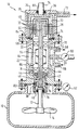
- an agitator 10 with, for example, a vertical shaft 12, at the lower end of which an agitator 14, e.g. a stirring propeller with several stirring arms is attached.
- this product can be a toxic, a radioactive, an aggressive or an explosive medium or also a solid suspension, in which case a practically leak-free seal to the outside is required.
- the shaft 12 is rotatably supported radially and axially in bearings 18, 20, in particular roller bearings, the bearings 18, 20 in turn being installed and supported in a housing part 22, the so-called bearing lantern.
- the storage lantern 22 is fixed to the product container 16, e.g. by screws, not shown, connected, an annular seal 82 being arranged between these two parts.
- a hood 24 is placed, which is also firmly connected to the former by screws, with a seal, e.g., between the hood 24 and the bearing lantern 22.
- a sealing ring 74 is used, as will be explained in more detail.
- the torque is transmitted to the shaft 12 via a magnetic coupling 26, which consists of an outer coupling part 30 and an inner coupling part 28, the outer coupling part 30 on its inner wall and the inner coupling part 28 on its outer circumference being occupied with permanent magnets 32.
- the outer coupling part 30 is rotatably installed within the hood 24 and coupled to a drive shaft 34 which extends through the hood 24 to the outside and which in turn is coupled to a drive motor, not shown, for driving the outer coupling part 30. Between the drive shaft 34 and the hood 24 a sealing ring 80 is arranged.
- the inner coupling part 28 is fixedly connected to the stirrer shaft 12 or, as in the example shown, it is made in one piece with it.
- a static sealing element 36 is installed between the inner coupling part 28 and the outer coupling part 30, which has an approximately cup-shaped shape and which is provided at its lower open end in the figure with a radially outwardly directed collar 84 which is located between the bearing lantern 22 and the hood 24 arranged together with the seal 74 and clamped together by the two parts 22, 24, with which the sealing element 36 effects a static hermetic seal of the interior of the agitator to the outside.
- the sealing element 36 which in the illustrated embodiment forms the so-called containment shell of the magnetic coupling 26, consists, for example, made of a metal-free fiber composite material and it separates the pressure range of the agitator from the atmosphere. When using such a material, undesirable eddy currents are avoided in the contactless transmission of the torque from the outer coupling part 30 to the inner coupling part 28.
- the sealing element 36 can also consist of an electrically conductive material, in which case cooling is expediently used, as is provided in the embodiment shown and described.
- a mechanical seal is installed between the stirrer shaft 12 and the housing part 22, which is formed from a stationary ring 38 and a ring 40 rotating with the shaft 12.
- An annular seal 76 is seated between the stationary ring 38 and the housing 22, and a sealing ring 78 is likewise arranged between the ring 40 rotating with the shaft 12 and the shaft.
- the mutually facing end faces of the two rings 38 and 40 slide against one another during operation to form a very narrow gap and the two rings of the mechanical seal are pressed against one another by the differential pressure between the pressure in the product container 16 and the pressure in the interior 86 of the housing.
- the pressure in the interior of the product container 16 is e.g. by a pressure gauge 62 and the pressure in the interior 86 of the housing is e.g. measured by a manometer 60.
- the slide rings can be made of SiC, Si / SiC or carbon, which can be combined with each other depending on the application. Among other things, they can also be used for solid suspensions and also for the treatment of sticky and crusty products.
- the mechanical seal can also be below the level of the product to be treated, i.e. immersed in this, be arranged.
- the interior 86 of the agitator housing between the mechanical seal and the static sealing element can be completely filled with a gas, e.g. Nitrogen can be filled, which can be filled in and refilled via a line 58.
- a gas e.g. Nitrogen can be filled, which can be filled in and refilled via a line 58.
- the bearings 18 and 20 are dry running bearings, e.g. made of ceramic materials or plastics.
- the interior 86 is filled with a lubricating fluid, either completely or to the extent that the upper bearing 20 is just immersed in the lubricant.
- a neutral gas in particular nitrogen, is filled in above the level of the product-neutral lubricant and between the lubricant level and the cup-shaped sealing element 36 maintain a gas cushion under pressure, through which the lubricating liquid is pressurized.
- the pressure in the gas cushion and thus in the lubricating liquid is kept via line 58 from an external gas supply to about 0 to about 3 bar above the pressure in the product container 16. This is also the case when the interior space 86 of the housing is completely filled with gas or completely with lubricating liquid.
- the pressure in the interior 86 is thus at least equal to the pressure in the product container 16, but preferably somewhat higher, no product can penetrate into the interior 86 from the product container 16.
- the lubricant not only serves to lubricate the mechanical seal, but also to cool and dissipate the heat generated on the mechanical seal and, if applicable, on the magnetic coupling.
- pumps 42, 48 and 54 are arranged on the shaft.
- the pump 42 sits between the mechanical seal and the lower bearing 18, it rotates with the shaft 12 and sucks in the lubricant via axial channels and throws the latter radially outwards due to the centrifugal force.
- Two overflow channels 44 are formed in the housing 22, which connect the area of the interior space 86 below the bearing 18 to the area above the bearing 18. (Of course, only one such overflow channel 44 or more than two channels can be provided).
- An overflow channel 46 is also formed in the shaft 12, which connects the area of the inner space 86 above the bearing 18 with the area directly at the mechanical seal, as a result of which the lubricant is circulated from the mechanical seal 38, 40 via the pump 42 and the overflow channels 44 the area of the interior 86 above the bearing 18 and from there back through the overflow channel 46 to the mechanical seal.
- the upper end of the shaft or the inner coupling part 28 in the figure is also provided with a pump 48 in the form of a transverse bore in the inner coupling part 28 above the permanent magnets 32, from which transverse bore branches an axial bore 50 in the shaft 12 and runs downwards until below the upper bearing 20, where the axial bore 50 opens into the interior 86 of the housing via a short transverse bore 52.
- a further overflow channel 70 is formed in the bearing lantern 22, which opens into the interior 86 above and below the upper bearing 20. (Only one such overflow channel 70 is shown, but several can also be provided).
- the heat from the mechanical seal 38, 40 can thus be dissipated by the pump 42 and the heat from the magnetic coupling 26 can be dissipated by the pump 48.
- a pump wheel 54 On the shaft, there is also connected in a rotationally fixed manner in the area between the two bearings 18 and 20, a pump wheel 54, through which the lubricant is circulated in the interior 86 in order to transfer the heat it contains to a housing cooling 64.
- the housing in particular the bearing lantern 22, is provided with cooling channels, e.g. 64, to which a coolant, e.g. Cooling water, supplied and discharged via a drain line 68.
- a coolant e.g. Cooling water
- the lubricating liquid is supplied or refilled via line 56, and its pressure and thus the pressure in interior space 86 is measured by manometer 60.
- a refill pump (not shown) for the lubricant is switched on and / or if necessary the pressure of the gas cushion is increased and an alarm is triggered. If the leakage increases, the agitator switches off automatically.
- the agitator is also switched off.
- the leakage can be drained off via a line 72 for combustion, for exhaust gas scrubbing or into a safety tank.
- the static sealing element 36 can form the housing for a drive motor, which is optionally coupled to the upper end of the stirrer shaft 12 via a gear. In this case, the entire drive, including any gear required, is then installed within the static, hermetically sealing element 36.
- the lower bearing can also be arranged in the product container 16 and the upper bearing in the region of the drive element, the mechanical seal then being located between the two bearings.
- the shaft with its bearings 18, 20, which are sealed by the mechanical seal 38, 40 and the static sealing element 36, can be completely surrounded by the product to be treated.
Landscapes
- Engineering & Computer Science (AREA)
- General Engineering & Computer Science (AREA)
- Mechanical Engineering (AREA)
- Sealing Devices (AREA)
- Sealing Of Bearings (AREA)
- Mechanical Sealing (AREA)
- Sealing Using Fluids, Sealing Without Contact, And Removal Of Oil (AREA)
Claims (14)
- Dispositif destiné à rendre étanches le palier et l'équipement moteur (28) d'un axe rotatif (12), en particuler d'agitateurs et/ou de rotors de pompes, dans des enceintes fermées (16), dans lesquelles sont traités des milieux ou des suspensions de matières solides agressifs, explosifs, radioactifs ou toxiques, l'axe (12) étant logé pour la mise en oeuvre dans un carter (22, 24) de façon que sa première extrémité sorte vers le produit à traiter, alors que, sur son autre extrémité, est monté l'équipement moteur (28), du côté moteur, entre l'axe (12) et l'équipement moteur (28), d'une part, et le carter (22, 24), d'autre part, est placé un élément statique d'étanchéité (36) pour assurer hermétiquement l'étanchéité, du côté produit entre l'axe (12) et le carter (22), est placée une garniture étanche à anneau glissant (38, 40) pour rendre étanche la chambre du produit par rapport à une chambre interne (86) du carter, dans laquelle sont placés des paliers (18, 20) pour l'axe (12) et l'équipement moteur (partie interne du dispositif d'accouplement) (28) relié d'une manière fixe à l'axe (12), l'élément statique étanche (36) rend hermétiquement étanche vers l'extérieur la chambre interne (86) du carter à l'atmosphère, et la chambre interne (86) du carter avec les paliers (18, 20), entre la garniture étanche à anneau glissant (38, 40) et l'élément statique étanche (36) est alimentée par un fluide sous pression qui est au moins environ égale, pourtant de préférence supérieure, à la pression dans l'enceinte du produit (16).
- Dispositif suivant la revendication 1, caractérisé en ce que l'équipement moteur est la partie interne d'un coupleur magnétique (26) fait d'une partie interne (28) et d'une partie externe (30), et en ce que l'élément statique étanche (36) est le pot de l'entrefer du coupleur magnétique (26).
- Dispositif suivant la revendication 1, caractérisé en ce que l'espace interne (86) du carter entre la garniture étanche à anneau glissant (38, 40) et l'élément statique étanche (36) est rempli d'un fluide lubrifiant.
- Dispositif suivant la revendication 3, caractérisé en ce que l'espace interne (86) du carter n'est rempli que partiellement, en particulier jusqu'au palier supérieur (20) de fluide lubrifiant et, au-dessus du niveau du fluide lubrifiant, est prévu un coussin de gaz, en particulier d'azote, par lequel le fluide lubrifiant est mis sous pression.
- Dispositif suivant la revendication 1, caractérisé en ce que l'espace interne (86) du carter entre la garniture étanche à anneau glissant (38, 40) et l'élément étanche statique (36) est rempli de gaz, en particulier d'azote.
- Dispositif suivant la revendication 3 ou 5, caractérisé en ce que la pression du fluide lubrifiant ou du gaz est supérieure d'environ 0 à 3 bars à la pression dans l'enceinte du produit (16).
- Dispositif suivant l'une des revendications précédentes, caractérisé en ce que, sur l'axe (12) entre le palier inférieur (18) et la garniture étanche à anneau glissant (38, 40), est montée une pompe (42) pour évacuer par le fluide lubrifiant la chaleur qui se produit à la garniture étanche à anneau glissant vers un refroidisseur de carter (64).
- Dispositif suivant l'une des revendications précédentes, caractérisé en ce que l'axe (12) est pourvu, à son extrémité supérieure, d'une pompe (48) pour évacuer par le fluide lubrifiant la chaleur de l'équipement moteur (28) vers un refroidisseur de carter (64).
- Dispositif suivant l'une des revendications 3 à 8, caractérisé en ce que, sur l'axe (12), en particulier entre les paliers (18, 20), est disposée une pompe (64) pour la circulation du moyen lubrifiant et l'évacuation de la chaleur vers un refroidisseur de carter (64).
- Dispositif suivant la revendication 2, caractérisé en ce que la partie externe (30) du coupleur magnétique (26) est enfermée d'une manière étanche par un capot (24) muni d'une conduite d'évacution (72).
- Dispositif suivant la revendication 1, caractérisé en ce que l'élément statique étanche (36) est le carter d'un moteur de commande qui est éventuellement couplé par un engrenage à l'axe (12).
- Dispositif suivant la revendication 1, caractérisé en ce que la garniture étanche à anneau glissant est disposée immergée dans le produit.
- Dispositif suivant la revendication 1, caractérisé en ce que l'axe avec ses paliers et l'équipement moteur, qui sont rendus étanches par la garniture étanche à anneau glissant et l'élément statique étanche, est entouré complètement par le produit.
- Dispositif suivant l'une des revendications précédentes, caractérisé en ce que la pression différentielle sur la garniture étanche à anneau glissant (38, 40) se monte à environ 0 à 15 % de la pression dans l'enceinte du produit (16).
Applications Claiming Priority (2)
| Application Number | Priority Date | Filing Date | Title |
|---|---|---|---|
| DE3818890 | 1988-06-03 | ||
| DE3818890A DE3818890A1 (de) | 1988-06-03 | 1988-06-03 | Anordnung zur sicheren abdichtung der lagerung einer rotierenden welle mit zugehoerigem antriebselement |
Publications (3)
| Publication Number | Publication Date |
|---|---|
| EP0344532A2 EP0344532A2 (fr) | 1989-12-06 |
| EP0344532A3 EP0344532A3 (en) | 1990-09-05 |
| EP0344532B1 true EP0344532B1 (fr) | 1994-07-13 |
Family
ID=6355767
Family Applications (1)
| Application Number | Title | Priority Date | Filing Date |
|---|---|---|---|
| EP89108965A Revoked EP0344532B1 (fr) | 1988-06-03 | 1989-05-18 | Dispositif d'étanchéification du palier d'un axe tournant avec son équipement moteur |
Country Status (4)
| Country | Link |
|---|---|
| US (1) | US5108715A (fr) |
| EP (1) | EP0344532B1 (fr) |
| AT (1) | ATE108525T1 (fr) |
| DE (2) | DE3818890A1 (fr) |
Families Citing this family (39)
| Publication number | Priority date | Publication date | Assignee | Title |
|---|---|---|---|---|
| FR2672636B1 (fr) * | 1991-02-12 | 1995-01-13 | Bertin & Cie | Machine tournante du type compresseur ou turbine pour la compression ou la detente d'un gaz dangereux. |
| DE4135709C1 (fr) * | 1991-10-30 | 1993-05-19 | Blohm + Voss Ag, 2000 Hamburg, De | |
| DE4214848C2 (de) * | 1992-05-05 | 1995-09-14 | John Crane Gmbh | Permanentmagnetische Zentralkupplung mit Spalttopf von getrennten Wellen |
| US5308229A (en) * | 1992-06-03 | 1994-05-03 | Pmc Liquiflo Equipment Company | Pump having an internal gas pump |
| US5368390A (en) * | 1993-03-01 | 1994-11-29 | General Signal Corporation | Mixer systems |
| DE4310266A1 (de) * | 1993-03-30 | 1994-10-06 | Draiswerke Gmbh | Mischer |
| DE9310578U1 (de) * | 1993-07-15 | 1994-11-17 | Feodor Burgmann Dichtungswerke GmbH & Co, 82515 Wolfratshausen | Sterilisierbare Antriebseinrichtung |
| US5879081A (en) * | 1995-01-09 | 1999-03-09 | Chordia; Lalit M. | Mixing apparatus having self-sealing spring-loaded seals |
| US5553867A (en) * | 1995-04-21 | 1996-09-10 | Environamics Corporation | Triple cartridge seal having one inboard and two concentric seals for chemical processing pump |
| JPH0989120A (ja) * | 1995-09-22 | 1997-03-31 | Pioneer Electron Corp | 真空装置 |
| US20040009610A1 (en) * | 1999-04-29 | 2004-01-15 | The University Of Wyoming Research Corporation D/B/A Western Research Institute | Organic contaminant soil extraction system |
| DE29923340U1 (de) * | 1999-08-26 | 2001-04-26 | Becker, Peter, Dipl.-Ing., 59423 Unna | Berührungsloses gas- und druckdichtes Antriebsmitnahmesystem |
| ES2189718T3 (es) * | 1999-11-10 | 2003-07-16 | Buss Sms Gmbh Verfahrenstechni | Mezclador y reactor. |
| US6572261B1 (en) | 2001-06-12 | 2003-06-03 | Walker Stainless Equipment Company | Horizontal agitator |
| DE10241026B4 (de) * | 2002-09-05 | 2004-09-30 | EISENMANN Maschinenbau KG (Komplementär: Eisenmann-Stiftung) | Transportwagen für eine Anlage zum Behandeln, insbesondere zum Lackieren, von Gegenständen, insbesondere von Fahrzeugkarosserien |
| US7670118B2 (en) * | 2003-02-03 | 2010-03-02 | Cap Co., Ltd. | Hot gas blowing fan |
| US6997601B2 (en) * | 2003-07-08 | 2006-02-14 | Feldmeier Equipment, Inc. | Agitator with removable blades for sanitary tank |
| TWI266468B (en) * | 2005-10-31 | 2006-11-11 | Sunonwealth Electr Mach Ind Co | Power indirectly linked towing apparatus |
| RU2310636C1 (ru) * | 2006-03-02 | 2007-11-20 | Федеральное государственное унитарное предприятие "Научно-исследовательский институт полимерных материалов" | Торцовое уплотнение вала смесителя взрывчатого состава и способ пропитки уплотнительного кольца из войлока для торцового уплотнения вала смесителя взрывчатого состава |
| US8512216B2 (en) * | 2007-11-08 | 2013-08-20 | Energysolutions, Llc | System for and method of filling a container with hazardous waste |
| EP2180583B1 (fr) | 2008-10-24 | 2012-08-08 | Biazzi Sa | Appareillage à cuve d'agitation |
| NL2002417C2 (en) * | 2009-01-15 | 2010-07-19 | Avantium Holding B V | Stir system. |
| CN101800464B (zh) * | 2010-01-28 | 2011-11-09 | 清华大学 | 高温气冷堆氦气空间的密封传动装置及其驱动装置 |
| SE534766C2 (sv) * | 2010-04-26 | 2011-12-13 | Itt Mfg Enterprises Inc | Genomföring för rötkammare |
| WO2014098746A1 (fr) * | 2012-12-21 | 2014-06-26 | Cassandra Oil Technology Ab | Réacteur étanche au gaz comportant un moyen d'écrasement rotatif |
| DE102013007849A1 (de) * | 2013-05-08 | 2014-11-13 | Ksb Aktiengesellschaft | Pumpenanordnung |
| US9945485B2 (en) * | 2015-05-04 | 2018-04-17 | Trelleborg Sealing Solutions Us, Inc. | Seal assembly for a sterile environment |
| DE102015005736A1 (de) * | 2015-05-07 | 2016-11-10 | Ika-Werke Gmbh & Co. Kg | Magnetkupplung sowie Rührvorrichtung mit Magnetkupplung |
| DE202016100655U1 (de) * | 2016-02-10 | 2017-05-11 | Speck Pumpen Vakuumtechnik Gmbh | Magnetkupplungspumpe |
| CN107120253A (zh) * | 2016-02-25 | 2017-09-01 | 衡阳瑞达电源有限公司 | 一种电泵 |
| JP2019196721A (ja) * | 2018-05-08 | 2019-11-14 | アイシン精機株式会社 | ウォータポンプ |
| CN111701523B (zh) * | 2020-06-28 | 2022-06-14 | 中国兵器装备集团自动化研究所 | 一种捏合安全传动装置 |
| CN112599275B (zh) * | 2021-02-02 | 2021-06-01 | 杭州景业智能科技股份有限公司 | 一种核工业用棒料碎屑去污封装系统的密封站口 |
| CN113757130B (zh) * | 2021-09-02 | 2024-04-02 | 安徽凯特泵业有限公司 | 一种自调节式化工泵 |
| CN114179409B (zh) | 2021-12-13 | 2023-09-29 | 山东豪迈机械科技股份有限公司 | 一种轮胎硫化设备 |
| CN114179410B (zh) | 2021-12-13 | 2023-09-29 | 山东豪迈机械科技股份有限公司 | 一种硫化设备 |
| US12203475B2 (en) * | 2022-08-23 | 2025-01-21 | Saudi Arabian Oil Company | Magnetic drive sealless pumps with steam jacket |
| CN116036950B (zh) * | 2023-02-02 | 2024-03-22 | 南通京源化工机械有限公司 | 一种使用寿命长的磁传动搅拌器 |
| DE102024002255B4 (de) | 2024-07-10 | 2026-04-30 | Idoneus Anlagenbau Gmbh | Antriebseinheit für ein Rührwerk mit Höhenverstellbarkeit in einem Prozessbehälter |
Family Cites Families (13)
| Publication number | Priority date | Publication date | Assignee | Title |
|---|---|---|---|---|
| US2698773A (en) * | 1951-03-17 | 1955-01-04 | Ohio Crankshaft Co | Lubricant cooling system |
| GB922319A (en) * | 1960-03-28 | 1963-03-27 | Klaus Franz | Centrifugal pump |
| US3106099A (en) * | 1960-11-09 | 1963-10-08 | Exxon Research Engineering Co | Fluid seal for a reciprocating shaft |
| US3749411A (en) * | 1971-07-19 | 1973-07-31 | Nettco Corp | Shaft sealing system |
| US4029323A (en) * | 1972-04-11 | 1977-06-14 | Nippon Seiko Kabushiki Kaisha | Fluid pressure seal arrangement |
| US4135253A (en) * | 1976-11-30 | 1979-01-23 | Medtronic, Inc. | Centrifugal blood pump for cardiac assist |
| US4415168A (en) * | 1977-04-12 | 1983-11-15 | Taiho Kogyo Co., Ltd. | Mechanical seal |
| US4234447A (en) * | 1978-07-17 | 1980-11-18 | The Dow Chemical Company | Mixing method and container therefor |
| GB2067823B (en) * | 1979-12-28 | 1983-05-11 | Kobe Steel Ltd | System for treating radioactive waste |
| US4582638A (en) * | 1981-03-27 | 1986-04-15 | General Signal Corporation | Method and means for disposal of radioactive waste |
| DE3341960A1 (de) * | 1983-11-21 | 1985-05-30 | EKATO Industrieanlagen Verwaltungsgesellschaft mbH u. Co, 7860 Schopfheim | Ruehrwerk |
| US4666676A (en) * | 1985-08-30 | 1987-05-19 | The United States Of America As Represented By The United States Department Of Energy | Radioactive waste processing apparatus |
| US4844707A (en) * | 1987-06-12 | 1989-07-04 | Kletschka Harold D | Rotary pump |
-
1988
- 1988-06-03 DE DE3818890A patent/DE3818890A1/de not_active Withdrawn
-
1989
- 1989-05-18 DE DE58908033T patent/DE58908033D1/de not_active Revoked
- 1989-05-18 EP EP89108965A patent/EP0344532B1/fr not_active Revoked
- 1989-05-18 AT AT89108965T patent/ATE108525T1/de not_active IP Right Cessation
- 1989-05-31 US US07/359,113 patent/US5108715A/en not_active Expired - Fee Related
Also Published As
| Publication number | Publication date |
|---|---|
| ATE108525T1 (de) | 1994-07-15 |
| DE3818890A1 (de) | 1989-12-07 |
| EP0344532A2 (fr) | 1989-12-06 |
| US5108715A (en) | 1992-04-28 |
| EP0344532A3 (en) | 1990-09-05 |
| DE58908033D1 (de) | 1994-08-18 |
Similar Documents
| Publication | Publication Date | Title |
|---|---|---|
| EP0344532A2 (fr) | Dispositif d'étanchéification du palier d'un axe tournant avec son équipement moteur | |
| DE1811100C3 (de) | Dichtungsanordnung | |
| DE1294936B (de) | Ruehrvorrichtung | |
| DE68921755T2 (de) | Dynamische dichtungsanordnung für eine schraubenpumpe. | |
| DE112006000814B4 (de) | Ultrareiner magnetischer Mischer | |
| DE2016493A1 (de) | Pumpenaggregat | |
| DE69705306T2 (de) | Hydraulische maschne | |
| EP0617999B1 (fr) | Mélangeur avec accouplement magnétique | |
| DE69914389T2 (de) | Dichtungsvorrichtung für Pumpen | |
| DE1653664A1 (de) | Selbstansaugende Zentrifugalpumpe | |
| DE3637501C2 (de) | Axialschubkompensation für Zentrifugalpumpen | |
| DE2160861B2 (de) | Schmier- und FUtereinrichtung für eine Umwälzpumpe | |
| EP0126239B1 (fr) | Joint d'étanchéité sans contact | |
| WO2013189571A1 (fr) | Pompe centrifuge de moteur pourvue d'une garniture étanche à anneau glissant | |
| DE69008598T2 (de) | Mechanische Dichtung. | |
| DE2460748B2 (de) | Umwaelzpumpe fuer insbesondere heizungs- und brauchwasseranlagen | |
| DE202016100655U1 (de) | Magnetkupplungspumpe | |
| EP1211422B1 (fr) | Moteur électrique à rotor noyé pour une pompe | |
| EP0359136A1 (fr) | Pompe centrifuge sans joint, nettoyable | |
| DE9207883U1 (de) | Reinigbare stopfbuchslose Kreiselpumpe | |
| EP0487882A1 (fr) | Garniture mécanique | |
| CH674419A5 (fr) | ||
| DE1053647B (de) | Hermetisch gekapseltes, elektrisches Motor-Pumpen-Aggregat | |
| DE19522557A1 (de) | Drehkolbenverdichter, insbesondere Vakuumpumpe | |
| DE19616553C1 (de) | Antriebsaggregat für Schienenfahrzeuge |
Legal Events
| Date | Code | Title | Description |
|---|---|---|---|
| PUAI | Public reference made under article 153(3) epc to a published international application that has entered the european phase |
Free format text: ORIGINAL CODE: 0009012 |
|
| AK | Designated contracting states |
Kind code of ref document: A2 Designated state(s): AT CH DE ES FR GB IT LI NL SE |
|
| PUAL | Search report despatched |
Free format text: ORIGINAL CODE: 0009013 |
|
| AK | Designated contracting states |
Kind code of ref document: A3 Designated state(s): AT CH DE ES FR GB IT LI NL SE |
|
| 17P | Request for examination filed |
Effective date: 19901207 |
|
| 17Q | First examination report despatched |
Effective date: 19920717 |
|
| GRAA | (expected) grant |
Free format text: ORIGINAL CODE: 0009210 |
|
| AK | Designated contracting states |
Kind code of ref document: B1 Designated state(s): AT CH DE ES FR GB IT LI NL SE |
|
| PG25 | Lapsed in a contracting state [announced via postgrant information from national office to epo] |
Ref country code: GB Effective date: 19940713 Ref country code: IT Free format text: LAPSE BECAUSE OF FAILURE TO SUBMIT A TRANSLATION OF THE DESCRIPTION OR TO PAY THE FEE WITHIN THE PRE;WARNING: LAPSES OF ITALIAN PATENTS WITH EFFECTIVE DATE BEFORE 2007 MAY HAVE OCCURRED AT ANY TIME BEFORE 2007. THE CORRECT EFFECTIVE DATE MAY BE DIFFERENT FROM THE ONE RECORDED.SCRIBED TIME-LIMIT Effective date: 19940713 |
|
| REF | Corresponds to: |
Ref document number: 108525 Country of ref document: AT Date of ref document: 19940715 Kind code of ref document: T |
|
| ET | Fr: translation filed | ||
| REF | Corresponds to: |
Ref document number: 58908033 Country of ref document: DE Date of ref document: 19940818 |
|
| PG25 | Lapsed in a contracting state [announced via postgrant information from national office to epo] |
Ref country code: SE Effective date: 19941013 |
|
| PG25 | Lapsed in a contracting state [announced via postgrant information from national office to epo] |
Ref country code: ES Free format text: LAPSE BECAUSE OF FAILURE TO SUBMIT A TRANSLATION OF THE DESCRIPTION OR TO PAY THE FEE WITHIN THE PRESCRIBED TIME-LIMIT Effective date: 19941014 |
|
| GBV | Gb: ep patent (uk) treated as always having been void in accordance with gb section 77(7)/1977 [no translation filed] |
Effective date: 19941013 |
|
| GBV | Gb: ep patent (uk) treated as always having been void in accordance with gb section 77(7)/1977 [no translation filed] |
Effective date: 19940713 |
|
| GBV | Gb: ep patent (uk) treated as always having been void in accordance with gb section 77(7)/1977 [no translation filed] |
Free format text: DATE CORRECTED TO 940713 |
|
| PLBI | Opposition filed |
Free format text: ORIGINAL CODE: 0009260 |
|
| 26 | Opposition filed |
Opponent name: FEODOR BURGMANN DICHTUNGSWERKE GMBH & CO. Effective date: 19950411 Opponent name: JOHN CRANE UK LIMITED Effective date: 19950411 |
|
| NLR1 | Nl: opposition has been filed with the epo |
Opponent name: JOHN CRANE UK LIMITED Opponent name: FEODOR BURGMANN DICHTUNGSWERKE GMBH & CO. |
|
| PGFP | Annual fee paid to national office [announced via postgrant information from national office to epo] |
Ref country code: DE Payment date: 19970523 Year of fee payment: 9 |
|
| PGFP | Annual fee paid to national office [announced via postgrant information from national office to epo] |
Ref country code: FR Payment date: 19970616 Year of fee payment: 9 |
|
| PGFP | Annual fee paid to national office [announced via postgrant information from national office to epo] |
Ref country code: AT Payment date: 19970619 Year of fee payment: 9 |
|
| PGFP | Annual fee paid to national office [announced via postgrant information from national office to epo] |
Ref country code: CH Payment date: 19970623 Year of fee payment: 9 |
|
| PGFP | Annual fee paid to national office [announced via postgrant information from national office to epo] |
Ref country code: NL Payment date: 19970630 Year of fee payment: 9 |
|
| RDAH | Patent revoked |
Free format text: ORIGINAL CODE: EPIDOS REVO |
|
| RDAG | Patent revoked |
Free format text: ORIGINAL CODE: 0009271 |
|
| STAA | Information on the status of an ep patent application or granted ep patent |
Free format text: STATUS: PATENT REVOKED |
|
| 27W | Patent revoked |
Effective date: 19971218 |
|
| REG | Reference to a national code |
Ref country code: CH Ref legal event code: PL |
|
| NLR2 | Nl: decision of opposition |