EP0344696A2 - Rotationskörper mit Hologrammen für optische Abtastzwecke - Google Patents
Rotationskörper mit Hologrammen für optische Abtastzwecke Download PDFInfo
- Publication number
- EP0344696A2 EP0344696A2 EP89109690A EP89109690A EP0344696A2 EP 0344696 A2 EP0344696 A2 EP 0344696A2 EP 89109690 A EP89109690 A EP 89109690A EP 89109690 A EP89109690 A EP 89109690A EP 0344696 A2 EP0344696 A2 EP 0344696A2
- Authority
- EP
- European Patent Office
- Prior art keywords
- spinner
- facet
- holographic scanner
- pattern
- radial
- Prior art date
- Legal status (The legal status is an assumption and is not a legal conclusion. Google has not performed a legal analysis and makes no representation as to the accuracy of the status listed.)
- Withdrawn
Links
Images


Classifications
-
- G—PHYSICS
- G02—OPTICS
- G02B—OPTICAL ELEMENTS, SYSTEMS OR APPARATUS
- G02B26/00—Optical devices or arrangements for the control of light using movable or deformable optical elements
- G02B26/08—Optical devices or arrangements for the control of light using movable or deformable optical elements for controlling the direction of light
- G02B26/10—Scanning systems
- G02B26/106—Scanning systems having diffraction gratings as scanning elements, e.g. holographic scanners
Definitions
- This invention relates to holographic scanner spinners.
- Holographic scanner spinners are devices which when positioned to intercept a stationary beam of light, such as from a laser diode, and rotated, cause the beam to scan.
- Holographic scanner spinners are known comprising a carrier substrate in the form of a disc, mountable for rotation about an axis at the center of the disc.
- the disc may be transparent or opaque depending on whether the holographic scanner spinner is of the transmission or reflection type.
- the disc may be regarded as divided onto a plurality of sector-shaped facets, that is, regions bounded by two radial lines extending radially from the axis of the disc and an arc concentric with the disc, the arc usually being a portion of the circular periphery of the disc.
- Each facet includes a diffraction grating pattern usually formed in a photoresist layer carried by the carrier substrate disc.
- the lines of the diffraction grating pattern of each facet may be "radial", that is, parallel to the radius which bisects the facet, or they may be "tangential", that is, perpendicular to the radius bisecting the facet.
- the diffraction grating pattern of a facet does not extend to the center of the disc.
- each diffraction grating pattern usually extends to the periphery of the disc or to a circle concentric with the disc and having a radius only slightly smaller than that of the disc.
- each diffraction grating pattern has usually had a shape bounded by parts of two radii and by inner and outer concentric arcs.
- each grating pattern should have an arcuate extent slightly greater than the arcuate extent of the facet so that the grating patterns of adjacent facets slightly overlap one another while the facets are only contiguous.
- diffraction gratings Many ways of making diffraction gratings are known. Ten ways are shown on page 101 of Diffraction Gratings by M. C. Hutley published in 1982 by Academic Press. In all of these ways, it is inherent that the larger the diffraction grating pattern, the larger must be the cross-section of the beam of light which is split and interfered with itself.
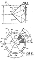
- One of the ways for producing diffraction gratings disclosed in the aforementioned book, is illustrated in Fig. 1 of the accompanying drawings. It will be observed that a beam 20 of coherent radiation from a laser, is directed at a prism 22. The portion of the beam 20 incident on facet 24 of the prism 22 is refracted downwards and the portion of the beam incident on the facet 26 is refracted upwards.
- the two portions of the beam interfere in the air space, contiguous with the base 28 of the prism, after they emerge from the base 28, and create a straight line interference pattern in that air space.
- Designated by 30 is a plane, parallel with the base 28 of the prism 22, in which lies the interference pattern having the greatest area. It will be observed that the maximum dimension d of the diffraction pattern which can be created on the plane 30 is directly related to the dimension D of the laser beam.
- the optical system used to create the interference patterns can also be smaller and hence less costly and probably more accurate.
- Figs. 2 and 2a illustrate a known holographic scanner spinner 32 comprising a substrate carrier disc 31 of rigid material having thereon a coating 29 of photoresist material.
- the disc 31 has a central aperture 27, for cooperation with a mounting and drive shaft (not shown) on an axis 33.
- the holographic scanner spinner has six facets 34, bounded by radial lines 35, each having an included angle of 60°.
- Each facet 34 includes a diffraction grating pattern 36 bounded by arcs of inner and outer circles 38 and 40, respectively, which are concentric with the holographic scanner spinner 32.
- the diffraction lines 42 of one pattern are represented in Fig. 2, on a greatly enlarged scale, of course, and are shown in one facet only. It will be observed that the lines 42 are parallel to the radius 43 which bisects the facet of which they are part.
- the illustrated holographic scanner spinner is a "radial holographic scanner spinner ".
- Fig. 3 illustrates a known mask 44 for defining the extent of the diffraction grating pattern to be created in each facet 34 of the holographic scanner spinner 32.
- the mask has an aperture 46 which is identical in shape and size to the diffraction grating pattern to be created in each facet.
- the mask 44 also has a center point 48 which is the point of intersection of the lines of the two sides 47 of the aperture.
- the mask 44 is placed against a substrate carrier disk coated with photoresist and with the center 48 of the mask 44 coincident with the axis 33 of the disc.
- the prism 22 is so disposed that the disc takes the place of the plane 30 illustrated in Fig. 1, and the interference pattern fills the aperture 46.
- the edge 23 of the prism is disposed so that it is parallel to the radius 43 bisecting the facet.
- the prism and the dimension D of the light beam 20 are both big enough that the entire aperture 46 is illuminated and an interference pattern is created on the entire area of the photoresist uncovered by the aperture in the mask 44.
- the disc is rotated through exactly 60° and another exposure is made. This step and expose process is repeated until all six facets have been exposed. Thereafter the photoresist is etched and a holographic scanner spinner results.
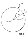
- Fig. 4 represents one facet 34 of the holographic scanner spinner which, for the purpose of the description, will be regarded as rotating counterclockwise, as indicated by the arrow 50. Also shown in Fig. 4 is the spot 52 created by the collimated beam of laser light which is to be converted from a stationary beam into a scanning beam by the rotating holographic scanner spinner.
- the spot is elliptical but, as is known, the spot may have other shapes.
- a holographic scanner spinner each facet of which has the same effective dimension but smaller maximum dimension considered circumferentially, whereby the optical system may be smaller or the same size optical system may be operated in a manner which allows higher quality to be achieved with the same size, and hence cost, of optical system.
- a holographic scanner spinner including a disc having an axis and a plurality of sector-shaped facets bounded by radial lines extending radially from the axis, each facet having a diffraction grating pattern, each pattern extends to the two radial lines bounding its facet in regions between a first and a second, greater radial distance from the axis and is spaced from the two radial lines in regions radially outwardly from the second radial distance.
- the aforesaid second radial distance is related to the radius of that circular path (termed herein "beam path") traveled by the widest portion of the beam, over the holographic scanner spinner.
- the term widest is intended to describe the largest dimension in the sense circumferentially of the holographic scanner spinner. It is at the intersection of the beam path with the radial line which is the boundary between adjacent facets, that the spot, created by the beam on the holographic scanner spinner, when on one facet, initially extends on to an adjacent facet as the holographic scanner spinner rotates in the beam. As long as the spot extends onto a second facet, the system including the holographic scanner spinner is useless for many purposes for which such systems are used. This uselessness is because the beam incident on two facets is split into two differently directed scanning beams. It is only when the holographic scanner spinner has rotated sufficiently that the spot is again on only one facet that the system becomes useful again.
- the diffraction grating there is no need for the diffraction grating to exist in regions of each facet which are traversed by the spot only when the spot is resident on two facets. Two such regions exist radially outwardly from the aforesaid beam path and contiguous with the facet-bounding radial lines. It is in these regions that the facet has the greatest width dimension, width being defined as a dimension measured perpendicularly to the radius bisecting the sector.
- the width of the grating pattern may be the same at radial distances greater than the aforesaid second radial distance as it is at the second radial distance.
- a holographic scanner spinner in accordance with the present invention having a performance identical to a holographic scanner spinner in accordance with the prior art, has grating patterns whose maximum widths are smaller.
- the grating patterns may be created with a smaller optical system or may have superior quality when made with the same optical system.
- the aperture in the mask of the prior art has the reference numeral 46 and the reference numeral for the aperture in the mask for making a holographic scanner spinner in accordance with the present invention is 146.
- a holographic scanner spinner 132 in accordance with the present invention.
- the holographic scanner spinner 132 includes a substrate carrier disc, formed of rigid material, for example, glass, and similar to the disc 31 illustrated in Fig. 2a. There is a coating 129 of photoresist material on the disc.
- the disc has a central aperture 127, again for cooperation with a mounting and drive shaft on an axis 133.
- the holographic scanner spinner 132 has six facets 134, bounded by radial lines 135, each having an included angle of 60°. Each facet 134 includes a diffraction grating pattern 136.
- the facets 134 differ from the facets 34 in that the diffraction grating patterns 136 do not occupy entirely the regions bounded by arcs of inner and outer circles 138 and 140, respectively, which are concentric with the axis 133, and by adjacent facet-bounding radial lines 135.
- each of the diffraction grating patterns 136 occupies a region bounded by a) circles 138 and 140; b) portions of radial lines 135 extending between the circle 138 and another circle 170; and c) lines 172 extending between the circle 170 and the circle 140, which lines 170 are parallel to the radius 143 bisecting the facet 134.
- the circle 138 has a first radius r1 and the circle 170 has a larger radius r2.
- the diffraction grating pattern bends to the two radial lines bounding its facet in regions between a first radial distance r1 and a second, greater radial distance r2 but is spaced from the radial lines 135 in regions radially outwardly from the second radial distance r2.
- the width of the pattern being regarded as the dimension in the direction perpendicular to the radius bisecting the facet,* then the width of the pattern is at least as great as the width of the facet out to approximately the beam path (as defined above), and is less than the width of the facet radially outwardly from the beam path.
- the pattern has a width "at least as great as” the width of the facet because there has been a recent proposal for adjacent diffraction grating patterns to overlap slightly at, and to each side of, the radial line defining the border between adjacent facets and in such cases the pattern has a "width" somewhat greater than the width of the facet where there is such overlap.
- a grating pattern extends to a radial line, it is to be understood that the term extends to does not mean that the grating pattern ceases at the radial line.
- “extends to” includes extending beyond.
- Fig. 6 illustrates a diffraction grating pattern 134 of a holographic scanner spinner in accordance with the present invention (labelled "invention embodiment” in the lower part of the Figure) and a pattern 34 in accordance with the prior art (labelled “prior art” in the upper part of the Figure).
- the upper part of the Figure is, of course, similar to Fig. 4.
- Fig.6 serves to demonstrate how two facets, which perform identically in use, have different maximum widths (width being as defined above).
- the maximum width of the pattern of the prior art holographic scanner spinner is W and the maximum width of the pattern of the holographic scanner spinner in accordance with the present invention is the smaller dimension w.
- radius of circle 140 which is the radially outer boundary of each grating pattern.... 2.188"
- radius r1 of the circle 138 which is the radially inner boundary of each grating pattern....0.7000”
- radius r2 of the circle 170 the beam path.
- number of facets....6 width w i.e. maximum width of grating pattern; see Fig. 6)
- .1.465 the following dimensions exist: radius of circle 140 which is the radially outer boundary of each grating pattern.... 2.188"; radius r1 of the circle 138 which is the radially inner boundary of each grating pattern....0.7000” radius r2 of the circle 170 (the beam path).
- width W i.e. maximum width of grating pattern; see Fig. 6).... 2.188";
- the present invention allows the maximum width of each facet to be reduced from 2.188" to 1.465" which is a 33% reduction. Because each grating pattern is smaller, the optical system used to create the pattern may be smaller and hence cheaper. Also, if the optical system illustrated in Fig. 1 is used to make the grating patterns, the waist of the exposing beam can be reduced, if radial type grating patterns are being produced. Reduction in the beam size decreases the exposure time which allows a higher rate of production as well as a reduction in cross scan error. The cross scan error can be reduced because the grating constant varies less from facet to facet.
- the primary cause of variation in grating constant is drift in the exposing system during the time the several facets of one holographic scanner spinner are being exposed. It has been found that the shorter the time to complete the exposure of all the facets of one holographic scanner spinner, the less drift there will be and the less variation there will be in the grating constant of the patterns in the one holographic scanner spinner. Also it has been found in some embodiments that there is a slight improvement in diffraction efficiency uniformity across each grating pattern. It is believed that this improvement may be due to improved developer kinetics adjacent the edge of the grating pattern where it is not contiguous with another grating pattern, that is, radially outwardly from the circle 170.
- the benefit may be taken as the ability to create radial holographic scanner spinners with larger grating patterns, with an optical system which, prior to the present invention, could make only smaller grating patterns, and to achieve in those larger grating patterns the same quality as was achieved in the smaller grating patterns.
- Those familiar with holographic scanners know that, in many uses, advantages are achieved from reducing the size of the scanned spot of light. They will also know that if the scanned spot size is reduced, the size of the spot on the holographic scanner spinner has to be increased. If the spot size on the holographic scanner spinner is increased, it is probably necessary to increase the facet and grating pattern sizes. Thus, there is a great desire to increase grating pattern sizes with reasonable cost and good quality.
- a holographic scanner spinner in accordance with the present invention is usable in holographic scanners which, for example, may be used for writing information contained in a stationary beam of light, along lines on a photosensitive material.
Landscapes
- Physics & Mathematics (AREA)
- General Physics & Mathematics (AREA)
- Optics & Photonics (AREA)
- Mechanical Optical Scanning Systems (AREA)
- Holo Graphy (AREA)
- Diffracting Gratings Or Hologram Optical Elements (AREA)
Applications Claiming Priority (2)
| Application Number | Priority Date | Filing Date | Title |
|---|---|---|---|
| US200289 | 1988-05-31 | ||
| US07/200,289 US4840443A (en) | 1988-05-31 | 1988-05-31 | Holographic scanner spinner |
Publications (2)
| Publication Number | Publication Date |
|---|---|
| EP0344696A2 true EP0344696A2 (de) | 1989-12-06 |
| EP0344696A3 EP0344696A3 (de) | 1991-07-24 |
Family
ID=22741084
Family Applications (1)
| Application Number | Title | Priority Date | Filing Date |
|---|---|---|---|
| EP19890109690 Withdrawn EP0344696A3 (de) | 1988-05-31 | 1989-05-30 | Rotationskörper mit Hologrammen für optische Abtastzwecke |
Country Status (3)
| Country | Link |
|---|---|
| US (1) | US4840443A (de) |
| EP (1) | EP0344696A3 (de) |
| JP (1) | JPH0625829B2 (de) |
Families Citing this family (7)
| Publication number | Priority date | Publication date | Assignee | Title |
|---|---|---|---|---|
| US5064258A (en) * | 1988-12-09 | 1991-11-12 | Ricoh Company, Ltd. | Information reading device |
| US5046794A (en) * | 1990-03-30 | 1991-09-10 | Holotek Ltd. | Hologon scanner system |
| US5162929A (en) * | 1991-07-05 | 1992-11-10 | Eastman Kodak Company | Single-beam, multicolor hologon scanner |
| US7459241B2 (en) * | 2003-09-22 | 2008-12-02 | Seagate Technology Llc | Rotary apertured interferometric lithography (RAIL) |
| JP4741279B2 (ja) * | 2005-04-25 | 2011-08-03 | 野田通信株式会社 | 汚泥界面計測装置 |
| US8629977B2 (en) * | 2010-04-14 | 2014-01-14 | Digital Ally, Inc. | Traffic scanning LIDAR |
| JP2022508697A (ja) * | 2018-10-12 | 2022-01-19 | ブリスライツ,エルエルシー | レーザ投影装置および3d画像作成方法 |
Family Cites Families (3)
| Publication number | Priority date | Publication date | Assignee | Title |
|---|---|---|---|---|
| US3619033A (en) * | 1968-09-25 | 1971-11-09 | Sperry Rand Corp | Three-dimensional light beam scanner utilizing tandemly arranged diffraction gratings |
| US4728789A (en) * | 1986-12-08 | 1988-03-01 | International Business Machines Corporation | System for adjusting holographic scanner lockout voltage |
| US4787688A (en) * | 1987-09-28 | 1988-11-29 | Eastman Kodak Company | Hologon and method of manufacturing a hologon |
-
1988
- 1988-05-31 US US07/200,289 patent/US4840443A/en not_active Expired - Fee Related
-
1989
- 1989-05-30 EP EP19890109690 patent/EP0344696A3/de not_active Withdrawn
- 1989-05-31 JP JP1138989A patent/JPH0625829B2/ja not_active Expired - Lifetime
Also Published As
| Publication number | Publication date |
|---|---|
| JPH0225829A (ja) | 1990-01-29 |
| EP0344696A3 (de) | 1991-07-24 |
| JPH0625829B2 (ja) | 1994-04-06 |
| US4840443A (en) | 1989-06-20 |
Similar Documents
| Publication | Publication Date | Title |
|---|---|---|
| US5061025A (en) | Hologon scanner with beam shaping stationary diffraction grating | |
| US7538313B2 (en) | Optical encoder having a no track portion of an optical scale being placed at a position symmetrical to a light non-transparent portion within an irradiation region of incident light | |
| EP0547205B1 (de) | Einstrahl vielfarben holographisches abtastgerät | |
| WO1987006016A1 (en) | Scanning apparatus | |
| US5091798A (en) | Diffraction grating for optical scanning | |
| EP0348863B1 (de) | Laserstrahlblende | |
| US4840443A (en) | Holographic scanner spinner | |
| US5309272A (en) | Dual pass binary diffractive optical element scanner | |
| EP0309990B1 (de) | Hologon und Verfahren zu seiner Herstellung | |
| JP3188933B2 (ja) | 投影露光方法 | |
| US4032343A (en) | Method for production of rotationally symmetric non-spherical optical elements | |
| JPH0370206B2 (de) | ||
| US5255108A (en) | Method of maximizing the frequency of adjacent facet cross scan error such that the increased spatial frequency reduces the visual perception of the exposure error | |
| US5253088A (en) | Method to reduce cross scan error visibility during manufacture of a hologon | |
| JP2744178B2 (ja) | 長尺ホログラムレンズ作製方法 | |
| US6181447B1 (en) | Laser scanning unit | |
| RU1099747C (ru) | Устройство для записи радиальной дифракционной решетки | |
| KR930011828B1 (ko) | 광주사장치 | |
| JPH03257416A (ja) | 光ビーム走査装置 | |
| JPH03175612A (ja) | 露光装置 | |
| JPH0320711A (ja) | ホログラムディスク | |
| JPH07104107A (ja) | フレネルレンズ | |
| JPS6118729B2 (de) | ||
| KR20000032433A (ko) | 편향 디스크를 채용한 빔 주사장치 | |
| JPH0517530B2 (de) |
Legal Events
| Date | Code | Title | Description |
|---|---|---|---|
| PUAI | Public reference made under article 153(3) epc to a published international application that has entered the european phase |
Free format text: ORIGINAL CODE: 0009012 |
|
| AK | Designated contracting states |
Kind code of ref document: A2 Designated state(s): BE CH DE FR GB LI |
|
| PUAL | Search report despatched |
Free format text: ORIGINAL CODE: 0009013 |
|
| AK | Designated contracting states |
Kind code of ref document: A3 Designated state(s): BE CH DE FR GB LI |
|
| 17P | Request for examination filed |
Effective date: 19911128 |
|
| 17Q | First examination report despatched |
Effective date: 19931004 |
|
| STAA | Information on the status of an ep patent application or granted ep patent |
Free format text: STATUS: THE APPLICATION HAS BEEN WITHDRAWN |
|
| 18W | Application withdrawn |
Withdrawal date: 19931218 |