EP0344703A2 - Adaptateur pour rail de prise de courant triphasé - Google Patents
Adaptateur pour rail de prise de courant triphasé Download PDFInfo
- Publication number
- EP0344703A2 EP0344703A2 EP89109710A EP89109710A EP0344703A2 EP 0344703 A2 EP0344703 A2 EP 0344703A2 EP 89109710 A EP89109710 A EP 89109710A EP 89109710 A EP89109710 A EP 89109710A EP 0344703 A2 EP0344703 A2 EP 0344703A2
- Authority
- EP
- European Patent Office
- Prior art keywords
- contact
- adapter
- control shaft
- recess
- switching
- Prior art date
- Legal status (The legal status is an assumption and is not a legal conclusion. Google has not performed a legal analysis and makes no representation as to the accuracy of the status listed.)
- Ceased
Links
Images

Classifications
-
- H—ELECTRICITY
- H01—ELECTRIC ELEMENTS
- H01R—ELECTRICALLY-CONDUCTIVE CONNECTIONS; STRUCTURAL ASSOCIATIONS OF A PLURALITY OF MUTUALLY-INSULATED ELECTRICAL CONNECTING ELEMENTS; COUPLING DEVICES; CURRENT COLLECTORS
- H01R25/00—Coupling parts adapted for simultaneous co-operation with two or more identical counterparts, e.g. for distributing energy to two or more circuits
- H01R25/14—Rails or bus-bars constructed so that the counterparts can be connected thereto at any point along their length
- H01R25/142—Their counterparts
-
- H—ELECTRICITY
- H01—ELECTRIC ELEMENTS
- H01R—ELECTRICALLY-CONDUCTIVE CONNECTIONS; STRUCTURAL ASSOCIATIONS OF A PLURALITY OF MUTUALLY-INSULATED ELECTRICAL CONNECTING ELEMENTS; COUPLING DEVICES; CURRENT COLLECTORS
- H01R29/00—Coupling parts for selective co-operation with a counterpart in different ways to establish different circuits, e.g. for voltage selection, for series-parallel selection, programmable connectors
Definitions
- the invention relates to an adapter for a three-phase current extraction rail according to the preamble of claim 1.
- An adapter of this type is known from DE-OS 28 10 618.
- a locking device a slide with a resiliently supported telescopic insert, which is displaceable between the two switching shafts and allows a non-positive locking of the switching shafts.
- This locking device is relatively complicated and leads to a relatively large length.
- DE-OS 32 14 911 it is known to provide a locking device in an adapter with a spring-loaded pawl, which holds the locking device in its inoperative position when the adapter is not inserted into the power take-off rail. In the inserted position, the pawl emerges from a locking recess of the locking device and allows an actuator of the locking device to be rotated into a locking position.
- the object of the invention is to provide an adapter according to the preamble of claim 1, the locking device of which is of simpler construction and does not require a large overall length.
- the rocker according to the invention does not require any additional elements such as a telescopic insert or a spring. Since the rocker engages with the projections in the recesses of the selector shafts from the side, it leads to no increased length, rather allows the use of an existing, previously unused width.
- the width of the receiving channels of known current drain rails is different; for example, it varies between 14 mm and 15 mm.
- the distances between the two mutually parallel planes in which the conductors are arranged also vary, for example by 1 mm.
- the known adapters have the disadvantage that, despite the relatively slight deviations, they only fit exactly to one of these current drain rails, because either their engaging part is too wide compared to the receiving channel of the other current drain rail or the swing-out contact tongues are not properly connected to the respective conductors can be.
- the earth protection conductors are also attached differently, for example in the case of one current extraction rail the earth protection conductor is arranged in the vicinity of the opening of the receiving channel, while in another current extraction rail the earth protection conductor is arranged in the bottom of the receiving channel.
- the projections and recesses which force the correct insertion of the adapter are also so different that the adapters matching the individual busbars cannot be inserted into a different busbar.
- an embodiment according to claim 7 is preferably provided, preferably in the structurally simple designs according to claim 8 or 9.
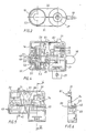
- the adapter 3 can be used in three different power rails 1, 1 ', 1 ⁇ .
- Each current extraction rail 1, 1 ', 1 ⁇ is provided with a receiving channel 2, in which an engaging part 4 of the adapter 3 can be used.
- an insulating profile 5 is used, each carrying two conductors 6, 7 'and 7, 7'.
- the conductors 6, 7, 7 ', 7 ⁇ are a neutral conductor 6 and three phase conductors 7, 7'and 7 ⁇ .
- An earth protection conductor 8 is arranged on the bottom of the receiving channel 2 of the current extraction rail 1. In the current extraction rail 1 Med, an earth conductor 8 is arranged on one side of the opening of the receiving channel 2.
- a pole channel 30, into which a pole rib 23 on a shoulder 11 of an outer part 10 of the adapter 3 can be inserted, is used for the correct insertion of the adapter 3 into the current extraction rail 1 ⁇ .
- Pole ribs 60 on the current drain rails 1 and 1 ' serve different adapters than that according to the embodiment.
- the current drain rails 1, 1 ', 1 ⁇ have on each side an inwardly, ie towards the receiving channel 2, directed rib 9. These ribs 9 are used for mechanical attachment of the adapter 3.
- the attachment is carried out in that after inserting the engaging part 4 of the adapter 3 into the receiving channel 2 one of the current drain rails 1, 1 ', 1 ⁇ a switching shaft 12 with the help of a switching lever 16 to 90 ° is pivoted, whereby two retaining bolts 13, 14 of the selector shaft 12 are pivoted over the ribs 9 and thus hold the adapter 3 on the power take-off rail 1, 1 'or 1'.
- the (in FIG. 1 right) shoulder 11 of the outer part 10 sits on its pole rib 60, which in this case is only used as a spacer, while the pole rib 23 of the adapter 3 is supported on the outside of a rib 9 (on the left in FIG. 1).
- the pole rib 23 of the adapter 3 engages in the pole channel 30 of the current drain rail 1 ⁇ .
- openings are provided on the side walls of the engaging part 4, through which openings the holding bolts 13 and 14 and contact tongues 15 and 18 from the engaging part 4 to the conductors 6, 7, 7 ', 7 ⁇ are pivotable.
- the adapter 3 is provided with two switching shafts 12 and 17 extending between the side walls of the engaging part 4 in the insertion direction.
- the first switching shaft 12 is provided with the retaining bolts 13 and 14, and with a radially resilient zero contact tongue 15.
- the second switching shaft 17 is provided with a phase contact tongue 18, which can be applied to the phase conductor 7 in a lower position and either in an upper axial position can be applied to the phase conductor 7 'or to the phase conductor 7 ⁇ .
- the second control shaft 17 can be axially shifted from a lower axial end position into an upper axial end position by the distance between two phase conductors 7, 7 ⁇ by means of a switch head 19.
- the second control shaft 17 in the upper axial end position when pivoting out the phase contact tongue 18 has an axial play of up to 1 mm.
- the latter is provided with a guide part 48 which is pivotably and axially displaceably guided in a link guide 49 in the intermediate position of the second control shaft 17. 4 and 5, this link guide 49 is molded into the half-shells 31 and 32.
- Conductors of a cable 29 held in a strain relief part 27 by means of a clamping screw 28 can be connected with the aid of an earth contact clamp 24 to a resilient earth contact tongue 21 and with resilient earth contact tabs 22, with the aid of a zero contact clamp 25 to the zero contact tongue 15 and with the aid of a phase contact clamp 26 to the phase contact tongue 18 will.
- only the half-shell 32 has to be removed in order to make all contact terminals 24, 25, 26 freely accessible. All movable parts of the adapter 3 can be inserted into the other half shell 31 and can be fixed in place by means of a clip 39. After connecting the conductors to the terminals 24, 25, 26, only the half-shell 32 is to be fastened by means of three fastening screws (cf. FIG. 2).
- the adapter 3 is provided with the resilient earth contact tabs 22 which engage through openings in a side wall of the engaging part 4 and protrude laterally and moreover the upper side of the engaging part 4 with the end contact tongue 21 springing into the engaging part 4.
- the adapter 3 When the adapter 3 is inserted into the current extraction rail 1, the earth contact tongue 21 rests on its earth protection conductor 8. The earth contact tabs 22 are pressed into the engaging part 4.
- the laterally projecting earth contact tabs 22 and the earth contact tongue 21 are formed from a multi-angled sheet metal part provided with the earth contact clamp 24, which is held by retaining bolts 61, which are formed on the half-shell 31, so that both a leg 62, the earth contact tongue 21st bears, as well as a leg that carries the laterally projecting earth contact tabs 22, can also deflect on the inside.
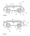
- the locking device for the two control shafts 12 and 17 consists of a rocker 41, which can be seen in particular in FIGS. 7 and 8 and which is mounted in the half-shell 31 so as to be pivotable about an axis 40 parallel to the axes of the control shafts 12 and 17 by less than 15 ° .
- the rocker 41 is mounted in a slot-like pocket 36 which is molded in the half-shell 31.
- the rocker 41 has at its swiveling ends rounded projections 42 and 43 which cooperate with recesses 44 and 45 in the control shafts 12 and 17 so that in the connected position of the first control shaft 12 the recess 44 is ready to receive the projection 42, so that when the second control shaft 17 rotates the recess 45 with one of its side walls pushes the other projection 43 out of its locked position and pivots the rocker 41 so that the first projection 42 engages in the recess 44 of the first control shaft 12 and locks it and in the non-contact Intermediate position of the second control shaft 17, the recess 45 of which is available for receiving the rounded projection 43.
- the pocket 36 is arranged under the top of a shoulder 11 of the outer part 10. In the central region of the pocket 36, a projection defining the axis 40 is formed, which for tiltable support of the rocker 41 engages in a U-shaped recess 47 in the back of the rocker 41.
- the second control shaft 17 is under the action of a return spring 52 which tends to press the control shaft 17 into the lower axial end position shown.
- the return spring 52 is housed in a cavity of the switch head 19.
- the switching head 19 is rigidly connected to the second switching shaft 17.
- the return spring 52 is supported, on the one hand, by a detached switch head cover 53 and, on the other hand, by a piston-like pressure part 50, which in turn is supported on a wall of the housing via two legs 51 which are guided through an upper wall of the switch head 19.
- the legs 51 protrude by the length of the adjustment path of the switch head 19 over the upper wall of the switch head 19.
- the second switching shaft 17 with the phase contact tongue 18, the phase contact terminal 26, the hollow switching head 19, the return spring 52 and the pressure part 50 form an assembly unit which is inserted into the half-shell 31 and held by a web wall of the holder 39.
Landscapes
- Details Of Connecting Devices For Male And Female Coupling (AREA)
- Driving Mechanisms And Operating Circuits Of Arc-Extinguishing High-Tension Switches (AREA)
Applications Claiming Priority (4)
| Application Number | Priority Date | Filing Date | Title |
|---|---|---|---|
| DE8807184U | 1988-06-01 | ||
| DE8807184U DE8807184U1 (de) | 1988-06-01 | 1988-06-01 | Adapter für dreiphasige Stromentnahmeschienen |
| DE3901500 | 1989-01-19 | ||
| DE3901500A DE3901500C1 (fr) | 1988-06-01 | 1989-01-19 |
Publications (2)
| Publication Number | Publication Date |
|---|---|
| EP0344703A2 true EP0344703A2 (fr) | 1989-12-06 |
| EP0344703A3 EP0344703A3 (fr) | 1992-01-02 |
Family
ID=25876915
Family Applications (1)
| Application Number | Title | Priority Date | Filing Date |
|---|---|---|---|
| EP19890109710 Ceased EP0344703A3 (fr) | 1988-06-01 | 1989-05-30 | Adaptateur pour rail de prise de courant triphasé |
Country Status (3)
| Country | Link |
|---|---|
| EP (1) | EP0344703A3 (fr) |
| DE (1) | DE3901500C1 (fr) |
| DK (1) | DK265889A (fr) |
Cited By (3)
| Publication number | Priority date | Publication date | Assignee | Title |
|---|---|---|---|---|
| EP0560445A1 (fr) * | 1992-03-13 | 1993-09-15 | Lumiance B.V. | Adaptateur |
| WO2001091249A1 (fr) * | 2000-05-24 | 2001-11-29 | Zumtobel Staff Gmbh | Systeme de barre omnibus |
| CN115320646A (zh) * | 2022-08-05 | 2022-11-11 | 中车青岛四方机车车辆股份有限公司 | 一种列车及其接地控制系统和方法 |
Families Citing this family (2)
| Publication number | Priority date | Publication date | Assignee | Title |
|---|---|---|---|---|
| DE9017281U1 (de) * | 1990-12-21 | 1991-04-11 | Semperlux GmbH Lichttechnisches Werk, 1000 Berlin | Adapter zwischen einer Stromschiene und einem Stromverbraucher |
| DE4406687C2 (de) * | 1994-03-01 | 1996-03-14 | Halloform Gmbh & Co Kg | Stromschienenadapter mit Phasenwähler |
Family Cites Families (4)
| Publication number | Priority date | Publication date | Assignee | Title |
|---|---|---|---|---|
| GB1436707A (en) * | 1972-07-21 | 1976-05-26 | Rotaflex Ltd | Electrical supply installations |
| DE2810681C2 (de) * | 1978-03-11 | 1982-04-08 | Erco Leuchten GmbH, 5880 Lüdenscheid | Adapter für ein- oder mehrphasige Stromentnahmeschienen |
| DE3214911A1 (de) * | 1982-04-22 | 1983-10-27 | Elektra GmbH & Co KG, 4904 Enger | Adapter fuer stromschienen |
| IT8321669U1 (it) * | 1983-04-28 | 1984-10-28 | Profilux Srl | Struttura di adattatore bipolare per linee elettriche multipolari di tipo blindato facenti parte di impianti per l'illuminazione di interni |
-
1989
- 1989-01-19 DE DE3901500A patent/DE3901500C1/de not_active Expired
- 1989-05-30 EP EP19890109710 patent/EP0344703A3/fr not_active Ceased
- 1989-05-31 DK DK265889A patent/DK265889A/da unknown
Cited By (5)
| Publication number | Priority date | Publication date | Assignee | Title |
|---|---|---|---|---|
| EP0560445A1 (fr) * | 1992-03-13 | 1993-09-15 | Lumiance B.V. | Adaptateur |
| WO2001091249A1 (fr) * | 2000-05-24 | 2001-11-29 | Zumtobel Staff Gmbh | Systeme de barre omnibus |
| EP2026425A2 (fr) | 2000-05-24 | 2009-02-18 | Zumtobel Lighting GmbH | Système de rail conducteur |
| EP2026425A3 (fr) * | 2000-05-24 | 2010-01-06 | Zumtobel Lighting GmbH | Système de rail conducteur |
| CN115320646A (zh) * | 2022-08-05 | 2022-11-11 | 中车青岛四方机车车辆股份有限公司 | 一种列车及其接地控制系统和方法 |
Also Published As
| Publication number | Publication date |
|---|---|
| DK265889A (da) | 1989-12-02 |
| DK265889D0 (da) | 1989-05-31 |
| EP0344703A3 (fr) | 1992-01-02 |
| DE3901500C1 (fr) | 1989-12-21 |
Similar Documents
| Publication | Publication Date | Title |
|---|---|---|
| DE2810681C2 (de) | Adapter für ein- oder mehrphasige Stromentnahmeschienen | |
| DE19835459C2 (de) | Anschlußklemme für elektrische Leiter | |
| DE2627843A1 (de) | Vorrichtung zur herstellung einer elektrischen verbindung | |
| DE2501008C2 (de) | Stromabnehmer mit Phasen-Vorwähleinrichtung für Kontaktschienen | |
| EP4084226B1 (fr) | Agencement de borne, borne de connexion et appareil électronique | |
| EP3316414A1 (fr) | Adaptateur de prise de courant de voyage pouvant être mis à la terre | |
| EP1271727B1 (fr) | Appareil d'installation électrique | |
| DE2336216A1 (de) | Elektrische anschlussvorrichtung | |
| DE3901500C1 (fr) | ||
| EP1523065B1 (fr) | Borne électrique | |
| DE3214911C2 (fr) | ||
| DE69709533T2 (de) | Verbindungsmodul mit Durchverbindung von Anschlüssen mittels eines oder mehreren beweglichen leitenden Teilen | |
| EP0465883B1 (fr) | Borne de connexion pour fixation sur un rail conducteur | |
| DE2706988A1 (de) | Schraubenlose anschlussklemme zur stromuebertragung von elektrischen leitern | |
| AT391226B (de) | Steckkontaktvorrichtung zum verbinden eines kabels mit einer stromschiene, insbesondere in einem schrank geringer tiefe | |
| DE2741219B2 (de) | Schaltervorrichtung | |
| EP1038109B1 (fr) | Appareil electrique a clip de raccordement et logement de clip de raccordement pour le raccordement a un deuxieme appareil electrique | |
| CH653181A5 (en) | Electrical connecting element | |
| DE3310496A1 (de) | Einrichtung zur bedienung von stellelementen bei elektrischen geraeten | |
| DE2739581C2 (de) | Drucktaster | |
| EP0227585B1 (fr) | Dispositif de sectionnement pour appareils interrupteurs montés d'une façon déplaçable sur glissières | |
| DE3201169A1 (de) | Vorrichtung zum festklemmen elektrischer leiter insbesondere von draehten | |
| DE8807184U1 (de) | Adapter für dreiphasige Stromentnahmeschienen | |
| EP0040324A2 (fr) | Commutateur à bouton-poussoir | |
| DE19530241A1 (de) | Schraubenlose Klemme |
Legal Events
| Date | Code | Title | Description |
|---|---|---|---|
| PUAI | Public reference made under article 153(3) epc to a published international application that has entered the european phase |
Free format text: ORIGINAL CODE: 0009012 |
|
| AK | Designated contracting states |
Kind code of ref document: A2 Designated state(s): AT BE CH DE ES FR GB GR IT LI LU NL SE |
|
| PUAL | Search report despatched |
Free format text: ORIGINAL CODE: 0009013 |
|
| AK | Designated contracting states |
Kind code of ref document: A3 Designated state(s): AT BE CH DE ES FR GB GR IT LI LU NL SE |
|
| 17P | Request for examination filed |
Effective date: 19920131 |
|
| 17Q | First examination report despatched |
Effective date: 19940125 |
|
| STAA | Information on the status of an ep patent application or granted ep patent |
Free format text: STATUS: THE APPLICATION HAS BEEN REFUSED |
|
| 18R | Application refused |
Effective date: 19940924 |