EP0344729A1 - Procédé et appareil de traitement du coton affecté par le miélat - Google Patents
Procédé et appareil de traitement du coton affecté par le miélat Download PDFInfo
- Publication number
- EP0344729A1 EP0344729A1 EP89109777A EP89109777A EP0344729A1 EP 0344729 A1 EP0344729 A1 EP 0344729A1 EP 89109777 A EP89109777 A EP 89109777A EP 89109777 A EP89109777 A EP 89109777A EP 0344729 A1 EP0344729 A1 EP 0344729A1
- Authority
- EP
- European Patent Office
- Prior art keywords
- microwave oven
- microwave
- fleece
- flakes
- cotton
- Prior art date
- Legal status (The legal status is an assumption and is not a legal conclusion. Google has not performed a legal analysis and makes no representation as to the accuracy of the status listed.)
- Granted
Links
Images

Classifications
-
- D—TEXTILES; PAPER
- D01—NATURAL OR MAN-MADE THREADS OR FIBRES; SPINNING
- D01G—PRELIMINARY TREATMENT OF FIBRES, e.g. FOR SPINNING
- D01G99/00—Subject matter not provided for in other groups of this subclass
-
- H—ELECTRICITY
- H05—ELECTRIC TECHNIQUES NOT OTHERWISE PROVIDED FOR
- H05B—ELECTRIC HEATING; ELECTRIC LIGHT SOURCES NOT OTHERWISE PROVIDED FOR; CIRCUIT ARRANGEMENTS FOR ELECTRIC LIGHT SOURCES, IN GENERAL
- H05B6/00—Heating by electric, magnetic or electromagnetic fields
- H05B6/64—Heating using microwaves
- H05B6/78—Arrangements for continuous movement of material
Definitions
- the present invention relates to a method and a device for reducing the stickiness of the fibers of cotton flakes contaminated with honeydew by the supply of heat.
- honeydew cotton flakes from some provinces are more or less infested with sugar-containing excretions from insects. These excretions containing sugar are commonly referred to as honeydew.
- a laboratory method is known by means of which the honeydew is caramelized by heating cotton flake samples in an oven, with the aim of determining the degree of contamination with honeydew from the change in the color of the cotton flake that occurs. This is very important because the cotton flakes become sticky in the event of heavy infestation and tend to stick to different parts of the yarn production system or to form rolls on rollers or other rotatable organs, which is very undesirable since it leads to frequent interruptions in the yarn production process .
- the object of the present invention is to provide a method and a device of the type mentioned at the outset, which selectively heats the honeydew component of the contaminated flakes with reduced energy expenditure.
- the flakes in the form of a fleece fleece or a flock of cotton wool are placed on a conveyor belt and a microwave oven constructed as a tunnel is moved therein and heated in the latter by means of microwave energy.
- the invention provides that the conveyor belt provided for the transport of the cotton flakes through the microwave oven consists of a means that absorbs little energy, in particular of polypropylene, and is deflected by two deflection rollers arranged at the entrance and exit of the tunnel-like oven, one of which can be driven. and that the roof of the housing of the microwave oven is designed as an extractor hood.
- the present invention is based on the finding that the water molecules contained in sugar or honeydew are preferred in microwave radiation Vibrations are set, whereby a greater heating of the honeydew component takes place in comparison to the remaining components of the flake fleece, whereby the honeydew components are converted into the desired non-tacky state.
- This selective heating of the honeydew component significantly reduces the amount of energy required for the process compared to other warming-up processes and prevents the temperature of the cotton flakes themselves from becoming too high, so that the risk of fire, which must always be taken into account when treating cotton flakes, is significantly reduced. This also largely avoids the risk of unwanted discoloration of the cotton flakes.
- the energy supply to the cotton flakes can take place in intermittent operation, ie the conveyor belt stands still in the oven while the fiber flakes placed thereon are heated up.
- the method is preferably carried out in continuous operation, ie the heating takes place during the movement of the conveyor belt through the tunnel.
- this has the advantage that the method according to the invention can be optimally integrated into the yarn production, in which a continuous supply of the fiber flakes to the card is desired.
- the fleece experiences a constant energy density and a correspondingly metered amount of energy in the tunnel due to the continuous movement, so that the honey dew constituents are heated up particularly uniformly, thereby avoiding local heating of the fleece to temperatures that would pose a fire hazard.
- the leveling out achieved by the movement can also reduce the Energy density in the fleece eliminates any form of wave stirrer.
- the vapors escaping during the supply of heat in the microwave oven are preferably drawn off during heating, as a result of which the fleece leaves the microwave oven in the dry state.
- a particularly preferred embodiment of the method according to the invention is characterized in that the fiber flakes remain in the oven for a time in the range from 5 to 30 and in particular for about 20 seconds and with a fleece width in the range from 80 to 120 cm and fleece thickness from 5 to 15 cm, the energy supply in the range of 50-300 kJ per kg of cotton, preferably around 175 kJ per kg of cotton.
- the values given are with conventional cotton processing equipment and with microwave generators available on the market, e.g. to reach the Gigatherm company.
- microwave generators with an output power of 1.2 kW each are required, which are preferably arranged in two rows.
- Control of the energy density can not only be achieved by controlling the output energy of each microwave generator, but it can also be varied within very broad limits by switching off one or more microwave generators. It is also possible to always equip the system with more microwave generators than for the highest degree of Contamination is necessary, so that if one or the other microwave generator fails, a new generator can be put into operation, which can significantly extend the period of use of the microwave oven.
- the entire oven can be bypassed or put out of operation without this having any adverse effects on the processing of the cotton flakes. E.g. it is not necessary to make any changes to the design of the entire fiber processing system.
- the microwave oven consists of several microwave generators which can be operated at the same time or individually, these, preferably if there are 10 to 14, in particular 12, microwave generators, are preferably arranged in two rows above the conveyor belt.
- microwave generators of a width of about 40 cm available on the market to arrange them side by side in two rows such that a nonwoven with a width of about 100 cm can be irradiated uniformly with microwaves.
- the width of 100 cm mentioned corresponds to the usual fleece width at the outlet of a mixer opener or flake feeder, as a result of which the microwave oven according to the invention can be easily integrated into an existing system.
- the microwave oven according to the invention or the method according to the invention or the device according to the invention can also be used for ginning.
- Ferrite rod assemblies arranged at the entrance and exit of the tunnel formed by the microwave oven. These ferrite rods protect the openings at the entrance and exit of the microwave oven, whose housing otherwise consists of continuous metal sheets, against any escape of microwave radiation.
- shielding plates are preferably arranged on the input and output sides before and after the tunnel formed by the microwave generators, extending transversely to the movement of the fleece and ending immediately in front of its surface.
- the flake is fed to the conveyor belt through a flake shaft arranged at the input end of the microwave oven with take-off rollers arranged at its lower end.
- the fleece delivered at the outlet end of the microwave oven is preferably fed to a disintegration unit of a cleaning machine which feeds a flock feeder connected upstream of one or more cards.
- the fleece can be cooled in a cooling zone operated with cooling air before being fed to the dissolving unit, as a result of which the stickiness of the honey dew is reduced even further.
- a particularly preferred embodiment of the device according to the invention is characterized in that alarm sensors are arranged inside the housing of the microwave oven and via a control system with a halon gas Fire extinguishing system are coupled. Should a fire arise in the microwave oven from any unforeseeable circumstances, the fire extinguishing system is able to extinguish this fire while switching off the microwave generator. This enables effective fire fighting within the quasi-closed microwave oven.
- reference numeral 13 denotes the outlet shaft of a combined mixing and cleaning machine 10, e.g. Rieter Unimix B 7/3 or mixer opener B 3/3, which is arranged in front of the microwave oven 11 according to the invention, which is followed by a dissolving unit 12.
- This disintegration unit can be the disintegration unit of a fine cleaning machine, e.g. of the Rieter ERM cleaner.
- the first deflecting roller 19 is already arranged shortly after the pair of draw rollers 15, 16 of the combined cleaner 10 and is separated from it by means of a guide plate 22 for the fleece 17.
- the driven deflection roller 21 is located immediately after the exit of the microwave oven 11 in front of the feed rollers 23, 24 of the opening unit 12, which in the further course of the nonwoven fabric 17 consists of feed rollers 25, 26, a cleaning roller 27 and a grate 28.
- the fleece 17 obtained from the conveyor belt is dissolved and cleaned by the cleaning roller 27 and the dissolved flakes are then fed into a shaft 29 rising vertically upwards, which leads to a flake feeder (not shown).
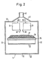
- the microwave oven 11 consists of two rows 30.1, 30.2 of six microwave generators 31 each.
- the fleece 17 deposited on the conveyor belt which has a width of 1 m and a thickness of approximately 10 cm, is approximately 15 cm below the lower ends of the microwave generators 31, so that the microwaves emitted by these microwave generators have the possibility of being distributed evenly over the width of the fleece. This distribution is started by multiple reflections on the metallic walls 32 of the microwave housing 33 or on a metallic support plate 35 provided below the upper run 34 of the conveyor belt 18 increases.
- shielding plates 36 are provided which are attached on the input and output sides and extend from the underside of the microwave generator to just above the surface of the fleece 17. Furthermore, around the rectangular inlet 37 and around the rectangular outlet 38 of the microwave oven, respective parallel arrangements of ferrite rods 39, 41 are arranged, which absorb any microwaves that are still present and thus prevent these microwaves from entering the housing of the combined cleaning machine 10 or in this way get to the dissolving unit 12. This keeps the radiation away from the operating personnel.
- the top of the microwave oven housing 33 is designed as an extractor hood 42, a fan (not shown) extracting the vapors generated by the microwave heating via a nozzle 43 provided at the upper end of the hood 42.
- Various IR detection sensors 44 are provided within the housing 33 and are connected to a control system. If local overheating occurs during operation, the system, especially the microwave generator 31, is switched off via the control system and a halon extinguishing gas is introduced into the housing via the nozzles 45, which displaces oxygen and prevents a fire or an emerging fire is extinguished immediately.
- the heat supply can be easily adjusted to the moisture content of the cotton and the honeydew contamination.
- the microwave devices themselves work with a 12 cm wavelength at a frequency of 2.45 gigahertz.
- the energy supply to the fleece should be dimensioned such that, taking into account the throughput speed of the conveyor belt, the honeydew deposits are warmed up to approximately 140 ° C., which is sufficient to extract approximately 80% of the water contained therein and the deposits in a readily processable, non-sticky state to convict.
- deflectors 46 which can be controlled within the microwave oven housing for controlling the microwaves, such deflectors 46 being shown in FIG. 2 between the adjacent rows 30.1, 30.2 by microwave generators. These deflectors can be controlled in such a way that a uniform energy distribution over the entire width of the fleece is obtained without the radiation obtained in the middle of the fleece from the two neighboring microwave generators leading to local overheating of the fleece or the honeydew deposits there.
- This Ab Wise are normally set once and for all in the manufacture of the microwave oven, taking into account the properties of the microwave generators installed there.
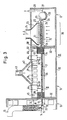
- FIG. 3 shows a variant of the device of FIG. 1 in that a cooling zone 70 is provided between the deflection roller 21 of the conveyor belt 18 and the feed rollers 23 and 24 in order to cool the heated fiber wadding between two cooling conveyor belts 71 and 72.
- the cooling zone 70 is covered by a suction hood 73, on which a connecting piece 74 is provided.
- This connection piece 74 is connected to a suction fan (not shown) in order to generate the air flow L through the cooling conveyor belts 71 and 72.
- Air inlet openings are provided in the walls which surround the cooling zone and the dissolving unit 12, to which the feed rollers 23 and 24 belong, in order to allow the aforementioned air flow L and the air for the shaft 29 to flow in.
- an air conditioning device (not shown) can be connected upstream of the aforementioned air inlet openings.
- the conveyor belts 71 and 72 are driven synchronously by a single drive (not shown) and convey the fiber wadding on the conveyor belt 18 at the output speed of the fiber wadding.
- the shaft 29 has a cross section and a length which enables cooling during the conveyance.
- the air speed in the shaft 29 will be slightly above the floating speed of the fiber flakes in order to allow a sufficient dwell time without too great a height of the shaft.
- conditioning the air sucked into the shaft 29 beforehand is also possible.
Landscapes
- Engineering & Computer Science (AREA)
- Textile Engineering (AREA)
- Physics & Mathematics (AREA)
- Electromagnetism (AREA)
- Treatment Of Fiber Materials (AREA)
- Preliminary Treatment Of Fibers (AREA)
- Jellies, Jams, And Syrups (AREA)
- Nonwoven Fabrics (AREA)
- Constitution Of High-Frequency Heating (AREA)
- Telephone Function (AREA)
Applications Claiming Priority (2)
| Application Number | Priority Date | Filing Date | Title |
|---|---|---|---|
| CH2121/88 | 1988-06-03 | ||
| CH212188 | 1988-06-03 |
Publications (2)
| Publication Number | Publication Date |
|---|---|
| EP0344729A1 true EP0344729A1 (fr) | 1989-12-06 |
| EP0344729B1 EP0344729B1 (fr) | 1995-06-21 |
Family
ID=4226369
Family Applications (1)
| Application Number | Title | Priority Date | Filing Date |
|---|---|---|---|
| EP89109777A Expired - Lifetime EP0344729B1 (fr) | 1988-06-03 | 1989-05-30 | Procédé et appareil de traitement du coton affecté par le miélat |
Country Status (9)
| Country | Link |
|---|---|
| US (2) | US5048156A (fr) |
| EP (1) | EP0344729B1 (fr) |
| JP (1) | JPH0226910A (fr) |
| KR (1) | KR920005792B1 (fr) |
| CN (1) | CN1019210B (fr) |
| AT (1) | ATE124097T1 (fr) |
| DE (2) | DE3819883A1 (fr) |
| IL (1) | IL90240A (fr) |
| RU (1) | RU1836505C (fr) |
Cited By (6)
| Publication number | Priority date | Publication date | Assignee | Title |
|---|---|---|---|---|
| EP0375629A1 (fr) * | 1988-12-21 | 1990-06-27 | Edoardo Polli | Procédé et appareil pour le traitement des balles de coton en vue d'enlèvement de champignons et des micro-organismes |
| US4989297A (en) * | 1985-02-28 | 1991-02-05 | Shenkar College Of Textile Technology And Fashion | Treatment of cotton |
| FR2664796A1 (fr) * | 1990-07-18 | 1992-01-24 | Moreau Sa | Procede de nettoyage de racines et tubercules, notamment de betteraves, apres leur arrachage. |
| EP0542166A1 (fr) * | 1991-11-15 | 1993-05-19 | CASCAMI SETA - FILATURE SERICHE RIUNITE SpA | Procédé et dispositif pour séparer le polypropylène dans le traitement de la soie |
| FR2685709A1 (fr) * | 1991-12-30 | 1993-07-02 | Cirad | Procede de traitement du coton et installation pour l'application du procede. |
| WO2005066404A1 (fr) * | 2003-12-19 | 2005-07-21 | Spinner, Hermann | Procede d'elimination des miellats et des fibres synthetiques des matieres fibreuses et dispositif pour la mise en oeuvre de ce procede |
Families Citing this family (15)
| Publication number | Priority date | Publication date | Assignee | Title |
|---|---|---|---|---|
| IL92299A0 (en) * | 1989-11-14 | 1990-07-26 | Israel Fiber Inst State Of Isr | Process and device for the treatment of cotton |
| FR2691545B1 (fr) * | 1992-05-20 | 1994-07-13 | Cirad | Procede et installation pour l'evaluation du caractere collant de matieres fibreuses vegetales telles que des cotons et utilisation de ce procede et de cette installation. |
| CN100379910C (zh) * | 2000-05-01 | 2008-04-09 | 爱克索雷拉公司 | 棉包热处理方法 |
| DE10104320A1 (de) * | 2001-01-25 | 2002-08-01 | Univ Schiller Jena | Vorrichtung zur Erfüllung von Sicherheitsfunktionen in Räumen mit Hochfrequenzstrahlung |
| CN1279418C (zh) * | 2001-12-24 | 2006-10-11 | Lg电子株式会社 | 用于平板显示器设备的铰接组件 |
| GB2397336B (en) * | 2001-12-24 | 2005-02-02 | Lg Electronics Inc | Hinge assembly for flat panel display appliance |
| MXPA04003745A (es) * | 2001-12-24 | 2004-07-23 | Lg Electronics Inc | Montaje de bisagra para aparato de visualizacion de tablero plano. |
| US20040188430A1 (en) * | 2003-03-31 | 2004-09-30 | Qazi Ghulam Nabi | Microbial decontaminator |
| CN100439840C (zh) * | 2006-01-05 | 2008-12-03 | 卓卫民 | 一种采用金属链条传动的微波加热设备 |
| DE102007063374A1 (de) * | 2007-12-30 | 2009-07-02 | Dieffenbacher Gmbh + Co. Kg | Verfahren und Vorrichtung zur Vorwärmung einer Pressgutmatte im Zuge der Herstellung von Holzwerkstoffplatten |
| US8046877B2 (en) * | 2008-08-26 | 2011-11-01 | Jimmy R. Stover | Drying of seed cotton and other crops |
| US20100307120A1 (en) * | 2009-06-05 | 2010-12-09 | Stover Jimmy R | Harvester with heated duct |
| CN103103704A (zh) * | 2012-12-11 | 2013-05-15 | 吴江兰瑞特纺织品有限公司 | 一种微波棉絮蓬松装置 |
| US9739530B2 (en) | 2014-02-28 | 2017-08-22 | Jimmy Ray Stover | Microwave drying of seed cotton and other crops |
| DE102017104061A1 (de) * | 2017-02-27 | 2018-08-30 | Dieffenbacher GmbH Maschinen- und Anlagenbau | Durchlaufofen zur Erwärmung von Material mittels Mikrowellen |
Citations (5)
| Publication number | Priority date | Publication date | Assignee | Title |
|---|---|---|---|---|
| CH557435A (fr) * | 1970-11-12 | 1974-12-31 | Oreal | Procede pour elever la temperature de fibres textiles. |
| GB2030440A (en) * | 1978-09-11 | 1980-04-10 | Philip Morris Inc | Method for the manufacture of fibrous articles |
| DE3430673A1 (de) * | 1984-08-21 | 1986-02-27 | Hermann Berstorff Maschinenbau Gmbh, 3000 Hannover | Einrichtung zum pasteurisieren und sterilisieren von rieselfaehigen materialien |
| EP0196449A1 (fr) * | 1985-02-28 | 1986-10-08 | THE SHENKAR COLLEGE OF TEXTILE TECHNOLOGY & FASHION | Procédé et dispositif pour mettre hors d'état de nuire une matière collante adhérente aux fibres de coton |
| DE3538899A1 (de) * | 1985-11-02 | 1987-05-07 | Hauni Werke Koerber & Co Kg | Anlage zur mikrowellenbehandlung eines gutes |
Family Cites Families (10)
| Publication number | Priority date | Publication date | Assignee | Title |
|---|---|---|---|---|
| DE175338C (fr) * | ||||
| GB433091A (en) * | 1934-07-25 | 1935-08-08 | Preston Street Combing Co Ltd | Improvements in combing machines |
| DE1133286B (de) * | 1959-10-06 | 1962-07-12 | Fritz Hadwich Dipl Ing | Verfahren und Vorrichtung zum Ausscheiden von festen und in der Hitze erweichbaren Fremdkoerpern aus einem Faserflor |
| GB1294648A (en) * | 1969-06-25 | 1972-11-01 | Unisearch Ltd | Apparatus for drying textile materials |
| NL189363C (nl) * | 1977-03-17 | 1993-03-16 | Truetzschler Gmbh & Co Kg | Inrichting voor het afnemen en samenvatten van uit een kaarde komend vezelvlies. |
| SU771425A1 (ru) * | 1978-11-02 | 1980-10-15 | За витель | Устройство дл сушки волокнистого материала |
| US4631380A (en) * | 1983-08-23 | 1986-12-23 | Durac Limited | System for the microwave treatment of materials |
| NL8402999A (nl) * | 1984-10-02 | 1986-05-01 | Philips Nv | Mikrogolfinrichting voor het verhitten van materiaal. |
| GB2182149B (en) * | 1985-10-25 | 1989-12-20 | Coal Ind | Improved moisture meter |
| IT8721377A0 (it) * | 1987-07-21 | 1987-07-21 | Edoardo Polli | Procedimento ed apparecchiatura per il trattamento di fibre tessili, in particolare di cotone in balle pressate, per la rimozione o riduzione da tali fibre di eventuali residui organici di insetti, ad esse aderenti. |
-
1988
- 1988-06-10 DE DE3819883A patent/DE3819883A1/de not_active Withdrawn
-
1989
- 1989-05-09 IL IL90240A patent/IL90240A/xx unknown
- 1989-05-30 DE DE58909304T patent/DE58909304D1/de not_active Expired - Fee Related
- 1989-05-30 RU SU894614194A patent/RU1836505C/ru active
- 1989-05-30 EP EP89109777A patent/EP0344729B1/fr not_active Expired - Lifetime
- 1989-05-30 AT AT89109777T patent/ATE124097T1/de not_active IP Right Cessation
- 1989-05-31 US US07/359,495 patent/US5048156A/en not_active Expired - Lifetime
- 1989-06-02 JP JP1139391A patent/JPH0226910A/ja active Pending
- 1989-06-03 KR KR1019890007651A patent/KR920005792B1/ko not_active Expired
- 1989-06-03 CN CN89103702A patent/CN1019210B/zh not_active Expired
-
1990
- 1990-04-02 US US07/503,524 patent/US5008978A/en not_active Expired - Fee Related
Patent Citations (5)
| Publication number | Priority date | Publication date | Assignee | Title |
|---|---|---|---|---|
| CH557435A (fr) * | 1970-11-12 | 1974-12-31 | Oreal | Procede pour elever la temperature de fibres textiles. |
| GB2030440A (en) * | 1978-09-11 | 1980-04-10 | Philip Morris Inc | Method for the manufacture of fibrous articles |
| DE3430673A1 (de) * | 1984-08-21 | 1986-02-27 | Hermann Berstorff Maschinenbau Gmbh, 3000 Hannover | Einrichtung zum pasteurisieren und sterilisieren von rieselfaehigen materialien |
| EP0196449A1 (fr) * | 1985-02-28 | 1986-10-08 | THE SHENKAR COLLEGE OF TEXTILE TECHNOLOGY & FASHION | Procédé et dispositif pour mettre hors d'état de nuire une matière collante adhérente aux fibres de coton |
| DE3538899A1 (de) * | 1985-11-02 | 1987-05-07 | Hauni Werke Koerber & Co Kg | Anlage zur mikrowellenbehandlung eines gutes |
Cited By (8)
| Publication number | Priority date | Publication date | Assignee | Title |
|---|---|---|---|---|
| US4989297A (en) * | 1985-02-28 | 1991-02-05 | Shenkar College Of Textile Technology And Fashion | Treatment of cotton |
| EP0375629A1 (fr) * | 1988-12-21 | 1990-06-27 | Edoardo Polli | Procédé et appareil pour le traitement des balles de coton en vue d'enlèvement de champignons et des micro-organismes |
| FR2664796A1 (fr) * | 1990-07-18 | 1992-01-24 | Moreau Sa | Procede de nettoyage de racines et tubercules, notamment de betteraves, apres leur arrachage. |
| EP0542166A1 (fr) * | 1991-11-15 | 1993-05-19 | CASCAMI SETA - FILATURE SERICHE RIUNITE SpA | Procédé et dispositif pour séparer le polypropylène dans le traitement de la soie |
| US5305497A (en) * | 1991-11-15 | 1994-04-26 | Cascami Seta-Filature Seriche Riunite Spa | Method to separate polypropylene in the processing of silk and device to separate polypropylene which employs such method |
| FR2685709A1 (fr) * | 1991-12-30 | 1993-07-02 | Cirad | Procede de traitement du coton et installation pour l'application du procede. |
| WO1993013253A1 (fr) * | 1991-12-30 | 1993-07-08 | Centre International En Recherche Agronomique Pour Le Developpement (Cirad) | Procede de traitement du coton par injection de vapeur d'eau chaude et installation pour la mise en ×uvre du procede |
| WO2005066404A1 (fr) * | 2003-12-19 | 2005-07-21 | Spinner, Hermann | Procede d'elimination des miellats et des fibres synthetiques des matieres fibreuses et dispositif pour la mise en oeuvre de ce procede |
Also Published As
| Publication number | Publication date |
|---|---|
| US5008978A (en) | 1991-04-23 |
| RU1836505C (ru) | 1993-08-23 |
| IL90240A0 (en) | 1989-12-15 |
| JPH0226910A (ja) | 1990-01-29 |
| CN1019210B (zh) | 1992-11-25 |
| ATE124097T1 (de) | 1995-07-15 |
| KR900000539A (ko) | 1990-01-30 |
| KR920005792B1 (ko) | 1992-07-18 |
| EP0344729B1 (fr) | 1995-06-21 |
| US5048156A (en) | 1991-09-17 |
| DE58909304D1 (de) | 1995-07-27 |
| DE3819883A1 (de) | 1989-12-07 |
| CN1040231A (zh) | 1990-03-07 |
| IL90240A (en) | 1993-02-21 |
Similar Documents
| Publication | Publication Date | Title |
|---|---|---|
| EP0344729B1 (fr) | Procédé et appareil de traitement du coton affecté par le miélat | |
| DE3003814C2 (de) | Verfahren und Vorrichtung zum Entfernen von Linters von Baumwollesamen | |
| DE3135247A1 (de) | Klimatisierung bei der herstellung genadelter fassenmatten | |
| DE60222150T2 (de) | Maschine und Verfahren für die kontinuierliche Behandlung einer Stoffbahn | |
| DE2755380A1 (de) | Vorrichtung zum oeffnen und reinigen von baumwollabfaellen | |
| DE10349374B4 (de) | Nassbehandlungsmaschine für strangförmiges Textilgut | |
| DE102019114016B4 (de) | Verfahren und Vorrichtung zur Erwärmung einer Pressgutmatte | |
| EP0344631B1 (fr) | Procédé et dispositif pour diminuer l'effet de mièlat du coton | |
| EP0352591A1 (fr) | Installation et procédé de traitement de matières textiles | |
| EP0350669B1 (fr) | Procédé pour réduire les matières adhérantes sur des fibres de coton souillées par des insectes | |
| DE3605100C2 (fr) | ||
| DE941384C (de) | Verfahren und Vorrichtung zur Herstellung von Fasern aus faserbildenden Werkstoffen | |
| DE4418248C2 (de) | Vorrichtung zum Herstellen eines Faservlieses | |
| DE2950367C2 (de) | Karde oder Krempel mit einer Umkleidung | |
| DE3616228A1 (de) | Vorrichtung zur kontinuierlichen waermebehandlung laenglicher textilprodukte | |
| DE4320638A1 (de) | Verfahren und Anlage zum raschen Abkühlen eines in einem Warmwalzwerk verarbeitenden Walzgutes | |
| DE10041838A1 (de) | Verfahren und Vorrichtung zum Beeinflussen von Struktur und Lage der Fasern im Prozeß der aerodynamischen Vliesbildung | |
| DE2365932C3 (de) | Verfahren zum mechanischen Herstellen von Rafffineurpulpe | |
| DE3509576C2 (fr) | ||
| WO1994003406A1 (fr) | Procede et dispositif de traitement thermique de dechets et/ou de residus | |
| DE2605003C3 (de) | Verfahren zur Herstellung von Faservliesen und Vorrichtung zur Durchführung des Verfahrens | |
| DE4124702A1 (de) | Vorrichtung zur ueberfuehrung eines faserflors in einen verdichter | |
| DE3501684C2 (fr) | ||
| AT244011B (de) | Verfahren zum Herstellen von Fasern aus zähflüssigen Massen und Vorrichtung zum Durchführen des Verfahrens | |
| DE2122039A1 (de) | Verfahren zur Herstellung eines Faserteppichs oder Faservlieses und Vorrichtung zur Durchführung dieses Verfahrens |
Legal Events
| Date | Code | Title | Description |
|---|---|---|---|
| PUAI | Public reference made under article 153(3) epc to a published international application that has entered the european phase |
Free format text: ORIGINAL CODE: 0009012 |
|
| AK | Designated contracting states |
Kind code of ref document: A1 Designated state(s): AT CH DE FR GB IT LI |
|
| 17P | Request for examination filed |
Effective date: 19900112 |
|
| 17Q | First examination report despatched |
Effective date: 19910709 |
|
| GRAA | (expected) grant |
Free format text: ORIGINAL CODE: 0009210 |
|
| AK | Designated contracting states |
Kind code of ref document: B1 Designated state(s): AT CH DE FR GB IT LI |
|
| PG25 | Lapsed in a contracting state [announced via postgrant information from national office to epo] |
Ref country code: FR Effective date: 19950621 |
|
| REF | Corresponds to: |
Ref document number: 124097 Country of ref document: AT Date of ref document: 19950715 Kind code of ref document: T |
|
| REF | Corresponds to: |
Ref document number: 58909304 Country of ref document: DE Date of ref document: 19950727 |
|
| ITF | It: translation for a ep patent filed | ||
| GBT | Gb: translation of ep patent filed (gb section 77(6)(a)/1977) |
Effective date: 19950829 |
|
| EN | Fr: translation not filed | ||
| PLBE | No opposition filed within time limit |
Free format text: ORIGINAL CODE: 0009261 |
|
| STAA | Information on the status of an ep patent application or granted ep patent |
Free format text: STATUS: NO OPPOSITION FILED WITHIN TIME LIMIT |
|
| PGFP | Annual fee paid to national office [announced via postgrant information from national office to epo] |
Ref country code: CH Payment date: 19960502 Year of fee payment: 8 |
|
| PG25 | Lapsed in a contracting state [announced via postgrant information from national office to epo] |
Ref country code: AT Effective date: 19960530 |
|
| 26N | No opposition filed | ||
| PG25 | Lapsed in a contracting state [announced via postgrant information from national office to epo] |
Ref country code: LI Free format text: LAPSE BECAUSE OF NON-PAYMENT OF DUE FEES Effective date: 19970531 Ref country code: CH Free format text: LAPSE BECAUSE OF NON-PAYMENT OF DUE FEES Effective date: 19970531 |
|
| REG | Reference to a national code |
Ref country code: CH Ref legal event code: PL |
|
| PGFP | Annual fee paid to national office [announced via postgrant information from national office to epo] |
Ref country code: GB Payment date: 20010423 Year of fee payment: 13 |
|
| REG | Reference to a national code |
Ref country code: GB Ref legal event code: IF02 |
|
| PGFP | Annual fee paid to national office [announced via postgrant information from national office to epo] |
Ref country code: DE Payment date: 20020502 Year of fee payment: 14 |
|
| PG25 | Lapsed in a contracting state [announced via postgrant information from national office to epo] |
Ref country code: GB Free format text: LAPSE BECAUSE OF NON-PAYMENT OF DUE FEES Effective date: 20020530 |
|
| GBPC | Gb: european patent ceased through non-payment of renewal fee |
Effective date: 20020530 |
|
| PG25 | Lapsed in a contracting state [announced via postgrant information from national office to epo] |
Ref country code: DE Free format text: LAPSE BECAUSE OF NON-PAYMENT OF DUE FEES Effective date: 20031202 |
|
| PG25 | Lapsed in a contracting state [announced via postgrant information from national office to epo] |
Ref country code: IT Free format text: LAPSE BECAUSE OF NON-PAYMENT OF DUE FEES Effective date: 20050530 |