EP0344882B1 - Resonanz-Abtastanlage mit geringer Vibration für ein optisches Miniatur-Anzeigegerät - Google Patents
Resonanz-Abtastanlage mit geringer Vibration für ein optisches Miniatur-Anzeigegerät Download PDFInfo
- Publication number
- EP0344882B1 EP0344882B1 EP89301850A EP89301850A EP0344882B1 EP 0344882 B1 EP0344882 B1 EP 0344882B1 EP 89301850 A EP89301850 A EP 89301850A EP 89301850 A EP89301850 A EP 89301850A EP 0344882 B1 EP0344882 B1 EP 0344882B1
- Authority
- EP
- European Patent Office
- Prior art keywords
- mirror
- vibrating
- mounting base
- vibrating structure
- unit according
- Prior art date
- Legal status (The legal status is an assumption and is not a legal conclusion. Google has not performed a legal analysis and makes no representation as to the accuracy of the status listed.)
- Expired - Lifetime
Links
Images


Classifications
-
- G—PHYSICS
- G02—OPTICS
- G02B—OPTICAL ELEMENTS, SYSTEMS OR APPARATUS
- G02B26/00—Optical devices or arrangements for the control of light using movable or deformable optical elements
- G02B26/08—Optical devices or arrangements for the control of light using movable or deformable optical elements for controlling the direction of light
- G02B26/10—Scanning systems
-
- G—PHYSICS
- G06—COMPUTING OR CALCULATING; COUNTING
- G06K—GRAPHICAL DATA READING; PRESENTATION OF DATA; RECORD CARRIERS; HANDLING RECORD CARRIERS
- G06K7/00—Methods or arrangements for sensing record carriers, e.g. for reading patterns
- G06K7/10—Methods or arrangements for sensing record carriers, e.g. for reading patterns by electromagnetic radiation, e.g. optical sensing; by corpuscular radiation
- G06K7/10544—Methods or arrangements for sensing record carriers, e.g. for reading patterns by electromagnetic radiation, e.g. optical sensing; by corpuscular radiation by scanning of the records by radiation in the optical part of the electromagnetic spectrum
- G06K7/10554—Moving beam scanning
- G06K7/10594—Beam path
- G06K7/10603—Basic scanning using moving elements
- G06K7/10633—Basic scanning using moving elements by oscillation
- G06K7/10643—Activating means
- G06K7/10653—Activating means using flexible or piezoelectric means
Definitions
- the present invention relates to a resonant vibrating light deflecting unit.
- Devices of this type are used to generate a raster scan image from a line of light-emitting devices.
- display devices which can visually display information such as figures, numbers and video information.
- These devices include the ubiquitous cathode ray tube in which a raster is created by repetitively sweeping an electron beam in a rectangular pattern. The image is created by selectively modulating the beam to generate light and dark spots on the raster.
- Another display device is an electromechanical scanning system in which a line of light-emitting devices is modulated with information to be displayed. The illuminated line is converted into a raster by means of an oscillating mirror thereby generating a virtual raster image.
- These latter devices have the advantage that a full "page" display can be created from a much smaller number of light-emitting devices than is necessary to generate a normal full page real image.
- an enlarged, virtual image of the illuminated devices is reflected from a mirror as the mirror is being physically pivoted about a fixed axis by means of an electromagnetic motor.
- an electromagnetic motor oscillates the mirror mass at the resonant frequency of the spring/mirror system. In this manner, only a small amount of power is needed to produce a relatively large oscillation.
- US-A-4632501 discloses such a resonant vibrating light deflecting unit, comprising a mounting base, a vibrating structure supporting a scanning mirror and resiliently mounted to the mounting base, and a driving motor means.
- Other light deflecting units of the same type are disclosed in US-A-4 453 170 and US-A-4 225 862.
- a problem with the conventional mirror/spring oscillator system is that the rapid angular oscillation of the mirror requires a large spring force to accelerate and decelerate the mirror.
- the spring force is also applied to the base of the device and constitutes a "reaction force". When the base is rigidly secured to a relatively massive object, this force is not a serious concern.
- the force causes vibrations which are, at best, annoying and, in some cases, may cause the resulting image to be blurred or even unintelligible.
- the vibration can disrupt the function of an accompanying instrument, such as a microscope, that is sensitive to vibration.
- the power required to oscillate the mirror increases when the vibration is transmitted to an external structure. This extra power means a larger motor is required to insure that the motor can drive the display with sufficient amplitude, in turn, resulting in increased battery drain for portable displays.
- a resonant vibrating light deflecting unit wherein there is a second vibrating structure resiliently mounted to the mounting base, the driving motor means is arranged to oppositely vibrate the vibrating structures, and the masses of the vibrating structures and the resilience with which each is mounted to the mounting base are such that the reaction forces in the mounting base, caused by the operational vibrations of the vibrating structures, substantially cancel each other.
- a method of reducing vibrations of a resonant vibrating light deflecting unit having a mounting base, a first vibrating structure supporting a scanning mirror and resiliently mounted to the mounting base, a second vibrating structure resiliently mounted to the mounting base, and a driving motor means arranged to oppositely vibrate the vibrating structures
- the method comprising the steps of: a) resiliently connecting the first vibrating structure to the base at a first point; b) resiliently connecting the second vibrating structure to the base at a second point, the second vibrating structure being selected so that the mechanical resonant frequency of the mirror and the first vibrating structure is substantially equal to the mechanical resonant frequency of the second vibrating structure; and d) positioning the first point relative to the second point so that the first reaction force substantially cancels the second reaction force at the base.
- the mirror support can consist of a "tuning-fork” configuration with the mirror mounted on one arm and a counterbalance mass mounted on the other arm.
- the driving motor may comprise a magnet and coil structure which drives one or more of the arms so that the arms move in opposite directions.
- the mirror is mounted to the base of the display device by crossed flexure springs.
- a counterbalance mass is also connected to the base of the video display device by a spring. The stiffness of both the mirror flexures and the counterbalance mass spring are selected so that the mirror and counterbalance mass have substantially the same resonant frequency.
- a voice-coil electromagnetic motor is used to drive the mirror and the counterbalance mass.
- the motor comprises a permanent magnet portion and associated magnetic return path mounted on one arm of the tuning fork configuration and a coil mounted on the other arm.
- a properly controlled current is applied to the coil, the permanent magnet is alternately attracted and repulsed from the coil. In this fashion, a driving force is applied to both the mirror and the counterbalance mass causing each to oscillate at the frequency of the driving force.
- the spring forces which accelerate and deaccelerate the mirror and counterbalance mass are also applied by the flexure springs to the base, and constitute "reaction forces".
- the geometry of the counterbalance mass and the counterbalance mass pivot point location are both selected so that the reaction force applied to the base by the counterbalance mass substantially cancels the reaction force applied to the base by the mirror.
- the geometry of the electromagnetic motor is selected so that the drive forces applied to the mirror and counterbalance mass are substantially equal to the air resistance forces acting on the mirror and counterbalance mass, with the result that little or no net force is applied to the base due to drive forces.
- Figure 1 is a schematic view of a typical prior art resonant electro mechanical scanner.
- Figure 2 is a partial cross-sectional view of a resonant scanner constructed in accordance with the present invention.
- Figure 3A is a schematic diagram of a miniature display using a scanning mirror which is pivoted near the mirror center.
- Figure 3B is a schematic diagram of a miniature display using a scanning mirror which is pivoted near the mirror end.
- Figure 4 is a perspective view of the resonant scanner shown in Figure 2.
- Figure 5 is a perspective view of a preferred embodiment of a resonant scanner utilizing a drive motor with improve efficiency.
- Figure 6 is a plan view of the preferred drive motor construction showing the mirror assembly overlaid by the counterbalance mass.
- Spring 42 which connects the mirror assembly to the base has been omitted for clarity.
- Figure 7 is a cross-sectional view of the preferred drive motor embodiment taken along the line 6-6 shown in Figure 6.
- Figure 8 is another cross-sectional view of the preferred drive motor embodiment taken along the line 7-7 shown in Figure 6.
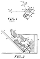
- Figure 9 is a longitudinal cross section of another embodiment using a sensor flag to sense position of the mirror 30.
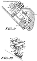
- Figure 10 is a partial exploded view of a portion of the embodiment shown in Figure 9 showing the voice coil with sensor flag, the counterbalance mass and the sensor assembly.
- Figure 11 is an electrical schematic diagram of an illustrative drive circuit.
- Figure 12 is a perspective view of a miniature optical display device utilizing an illustrative embodiment of the inventive scanner unit.
- FIG. 1 is a schematic diagram of a typical prior art resonant electromechanical scanner of the type shown in US-A-4632501. As this device is explained in detail in the latter patent, it will not be fully discussed herein.
- the resonant scanner is used in a scanned image display device of the type described in the applicants published specification No. EP-A-0301801, constituting prior art within the meaning of Article 54(3) EPC.
- the display device is described in detail in that application, which is hereby incorporated by reference, only a brief description of the operation will be given here.
- a row of light emitting devices 10 (which may illustratively be light-emitting diodes) is electrically excited to selectively emit light thereby generating an illuminated line.
- the row of LEDs extends perpendicularly into the page.
- the light from LED row 10 passes through an optical system schematically illustrated as lens 5, which creates an enlarged virtual image of the LED's.
- the image is reflected from mirror 30 to an observer's eye 15 as mirror 30 is repetitively oscillated in the direction arrow 16.
- Ny selectively illuminating the LEDs in row 10 as mirror 30 moves, a rectangular raster can be formed which van be observed by the viewer.
- the mechanism which moves the mirror is generally termed as resonant scanner. It consists of a base 20 to which plane mirror 30 is attached by means of a flat spring 34 which extends perpendicularly into the page. Mirror 30 is oscillated by a drive motor consisting of two cylindrical permanent magnets 44 and 45 and two ring coils 46 and 47. In operation, one of coils 46 and 47, for example coil 47, is excited and the corresponding permanent magnet, 45, is either attracted into coil 47 or repulsed depending on the relative magnetic fields produced by coil 47 and magnet 45. The resulting force causes mirror 30 to pivot around the attachment point with spring 34 so that mirror 30 oscillates in the direction of arrow 16.
- the remaining coil (coil 46 in the example) is used as a sensing coil to sense the motion of mirror 30.
- the electrical signals derived from the motion of magnet 44 relative to coil 46 are used by driving circuitry (not shown) to control the current provided to drive coil 47 in a conventional fashion and as described in the aforementioned Patent No. 4,632,501.
- the mass and geometry of mirror 30 and the spring constant of spring 34 are chosen so that a resonant mass system is formed at the desired operating frequency. In this manner, a large excursion angle for mirror 30 is produced by a driving force which is much lower than would be required if the mirror were driven in a non-resonant fashion.
- FIG. 2 shows a partial cross-sectional view of the mirror assembly of the present invention.
- mirror 30 is part of a balanced assembly with two arms.
- One arm comprises mirror 30, mirror support 36 and driving coil 46.
- the other arm consists of weight 40 and permanent magnet 44.
- the mirror arm is attached to base mounting 21 by means of two flexure springs 32 and 34.
- Springs 32 and 34 are both flat springs which extend into the page. As will be discussed hereinafter, two springs are used in a crossed arrangement to constrain rotation of the mirror assembly to a single axis.
- Mirror 30 is directly attached to a mirror support 36 (which may be comprised of a suitable plastic or other material) by means of adhesive or cement.
- a mirror support 36 which may be comprised of a suitable plastic or other material
- One end of spring 32 is attached to mirror support 36 by means of a screw or rivet or other fastener.
- the other end of spring 32 is attached to base mounting 21 by means of another fastener.
- a second spring, 34 is also attached to mirror support 36 by fastener 37 and to base 21 by fasteners 39.
- rectangular washers would generally be used with fasteners 39 in order to mechanically define the flexing point of the spring.
- the two flexure springs 32 and 34 act together so that mirror 30 and mirror support 36 effectively pivot around the point 48 at which springs 32 and 34 cross. Under influence of the driving motor, the mirror arm oscillates in the direction of arrow 16 around point 48.
- Weight 40 is attached to the one end of spring 42 by means of fastener 43.
- Spring 42 is also a flat spring extending into the page.
- the other end of spring 42 is attached to base 21 by means of fastener 45.
- Weight 40 thus effectively pivots around an intermediate point located on spring 42 between attachment points 43 and 45.
- Mirror 30 and weight 40 are driven by a voice-coil type electromagnetic motor consisting of permanent magnet 44 weight 40 and coil 46.
- Magnet 44 is rigidly secured to weight 40, while the coil 46 is rigidly secured to mirror support 36.
- Weight 40 is shaped with an overhanging portion 41 which acts to complete the magnetic flux return path and improve the efficiency of the motor.
- Circuitry is provided (not shown) to supply a sinusoidal current (or other periodic current, such as a square wave or current pulses) to the electrical coil 46.
- the electrical connections between coil 46 and the driving circuitry are provided through springs 32 and 34 in order to avoid separate wires which are subject to fatigue from flexing.
- the sinusoidal current in coil 46 generates a fluctuating magnet field which causes magnet 44 and coil 46 to be alternately attracted and repelled at the frequency of the current.
- the frequency of the sinusoidal driving current is chosen so that mirror 30 rotates through an arc segment at the resonant frequency of the spring/mass system consisting of mirror 30 and spring 32.
- the desired resonant frequency will depend upon the use of the scanner. In a scanned image display system as previously mentioned, the proper resonant frequency depends on the minimum display refresh rate to eliminate display "flicker".
- the resonant freqency can be selected in a conventional fashion by choosing the mass and geometry of mirror 30 and the spring constant of spring 32.
- the use of the illustrative structure allows a light-weight drive coil to be placed on the mirror assembly rather than requiring a heavy magnet structure to be placed on the mirror assembly.
- This arrangement allows the electromagnetic drive motor to be designed for efficient operation because the permanent magnet structure on the counterbalance arm can be large and heavy in order to produce a high magnetic field strength without contributing to the mass of the mirror arm.
- the illustrative scanner When used in a scanned image display, the illustrative scanner has an additional benefit. Since the effective mirror pivot point 48 is located away from the center of mirror 30, a smaller mirror can be used to produce an optical system with a given "exit pupil". This advantage is illustrated in Figures 3A and 3B which show two display systems each utilizing an oscillating scanner mirror. Elements and locations in Figures 3A and 3B which are equivalent to those elements and locations shown in Figure 2 are given the same numeral designations.
- Exit pupil 110 is defined as the area in which the user's eye 15 can be placed so as to see the entire image.
- a display system is constructed with a mirror pivoted near the center.
- the size of the exit pupil 110 is dependent on the arc through which the mirror swings and the geometry of the display.
- an exit pupil which has the same size as the exit pupil in Figure 3A can be achieved with a significantly smaller lens 5 and case size when the mirror is pivoted near one end according to one aspect of the present invention.
- Figure 4 shows a partial perspective view of the illustrative embodiment of the resonant scanning unit with an accompanying housing shown in partial phantom detail.
- Figure 4 illustrates the connection of flexure springs 32, 34 and 42 between mirror 30 and weight 40 and the base mounting 21.
- components which are equivalent to those shown in Figure 2 are given the same numeric designations.
- Flexure spring 34 is illustratively a U-shaped spring made out of a single layer of flat spring material.
- flexure spring 32 is a single layer flat spring which is mounted between the legs of spring 34 at a right angle to the plane of spring 32. This "crossed" spring design constrains movement of mirror mass 30 to essentially pure rotation whereas the single spring design common in conventional units is subject to undesirable twisting movements.
- Spring 42 is another U-shaped spring which fastens weight 40 to base 21.
- reaction forces on a mass/spring system can be represented by a pair of force vectors which act at a conceptual "point of percussion".
- point of percussion the actual moving part will have both mass and rotary moment of inertia these may be modeled as an equivalent point mass located at the point of percussion.
- a secondary force vector passes through the point of percussion and the system pivot point and represents centrifugal force.
- a primary force vector passes through the point of percussion and is perpendicular to the secondary force vector and represents the force needed to translate and rotate the mass about the pivot point.
- the primary force vector has a relatively large sinusoidal magnitude which causes the mirror to accelerate back and forth (the magnitude of the force is greatest at the extreme ends of travel of the mirror).
- This force depends only upon the equivalent mass of the mirror assembly and the amplitude of mirror travel and, with proper pivot point placement and design, can be substantially cancelled by the reaction forces generated by the counterbalance mass.
- the geometry of the mirror and counterbalance mass must be adjusted so that the primary force vectors are co-linear.
- this force is approximately 42 grams-force (gmf). It has been found that with a mirror mass of 3.36 grams, a counterbalance mass of 10.95 grams has produced effective cancellation of this force.
- a much smaller drag force also acts upon the mirror assembly.
- This force is primarily a velocity-proportional force due to air resistance.
- the "Q" value for the mirror assembly alone is approximately 100 resulting in a drag force of about 0.4 gmf (the "Q" value is a measure of damping and has to do with the sharpness of the resonant peak).
- voice coil motor 46 supplies a force to move mirror 30. If the drive force is a sine wave it can be made to substantially balance the previously-mentioned force resulting from drag.
- a drag force also acts on the counterbalance assembly.
- this latter force is approximately 0.2 gmf, corresponding to a "Q" of 200 for the counterbalance mass alone.
- the "Q" of the mirror assembly alone is lower because of its larger surface area.
- the motor torque exerted on the mirror and the counterbalance mass by the voice coil motor must be in the ratio of 0.4/0.2. The geometry of the illustrative embodiment has been designed to substantially accomplish this result.
- a sinusoidal drive force applied in the correct ratio theoretically results in substantially zero net drive-related forces applied to the base
- a non-sinusoidal drive force can also be used. If the drive force is periodic but not sinusoidal, a small net force will be applied to the base, but this force may be acceptable in view of simplifications possible in the motor drive circuitry.
- the vibration which is produced is acceptable.
- the resulting case vibration would be ⁇ 7 um.
- Figure 4 also shows the electrical connections of coil 46 through flexure springs 32 and 34. Since two separate flexure springs, 32 and 34, are used to support mirror 30 these springs may also be used in order to carry electrical current to coil 46 and, thus, eliminate the use of separate wires which may be subject to breakage due to repeated flexing.
- one electrical lead, 50, of coil 46 is attached to flexure spring 34 by means of fastener 37.
- Another electrical lead, 55 is attached to flexure spring 32 by means of fastener 35. Electrical connections to coil 46 can be completed by making appropriate electrical connections to the other ends of the flexure springs 32 and 34 at fasteners 33 and 39, respectively. Current is thus carried along the flexure springs directly to coil 46.
- Figures 5-8 show an alternative embodiment of a resonant scanner unit that uses a preferred construction of the voice coil motor.
- This preferred construction increases motor efficiency by achieving higher magnetic field strength in the air gap.
- inefficiency results because the air gap between the inside diameter of toroidal coil 46 and magnet 44 must be sufficient to accommodate the varying arcs through which mirror 30 and weight 40 move.
- the relatively large tolerance which is required in order to prevent physical collisions results in high flux leakage and low field strength in the air gap, and, thus, in poor motor efficiency.
- the motor design shown in Figures 5-8 improves motor efficiency by optimizing the magnetic circuit to reduce leakage flux.
- Parts of the assembly which remain the same as the embodiements shown in Figures 2 and 4 are designated with the same numerals.
- the toroidal-shaped coil 46 shown in Figure 4 is replaced by a rectangular coil 66 shown in Figures 5 and 6.
- weight 40 has been modified to have an "E" shape with three fingers, 70, 72 and 74 shown in the cross-sectional view of Figure 7.
- Central finger 72 fits into the rectangular opening 73 in coil 66 as shown in Figures 7 and 8.
- the two side fingers 70 and 74 are provided with magnets 73 and 75 which lie on the outside of coil 66 as shown in Figures 7 and 8.
- a slot 76 which is cut in weight 40.
- This slot is used to accommodate a mechanical sensor that senses the position of mirror 30 and generates electrical signals which control the driving current to ensure that mirror 30 and weight 40 oscillate at the desired resonant frequency.
- Figures 6-8 also shown an improved mechanism for attaching spring 42 to weight 40.
- spring 42 is clamped between two clamping members 45 and 47.
- Clamp members 45 and 47 have slots 51 (shown in Figure 6) which allow the members to be slid over fasteners 43.
- the ends of spring 42 which are fastened by fasteners 43 are not slotted, thus the distance between the wieght 40 and base 21 is mechanically fixed.
- clamping members 45 and 47 can be moved relative to weight 40, thus effectively changing the attachment point of spring 42 to weight 40.
- the effective spring length can be changed for the purposes of adjusting the resonant frequency without changing the basic geometry of the device.
- Figure 9 is a partial cross-section of the resonant scanning unit of Figures 5-8 fitted with a position sensor mechanism. The main components of this mechanism are also depicted in the partial exploded view shown in Figure 10.
- the sensor mechanism consists of a "flag" 80 which is mounted on one end of rectangular coil unit 66. When the unit is assembled, flag 80 extends between the two arms of LED/photocell sensing unit 90.
- sensing unit 90 consists of a mounting bracket 92 which is affixed to the scanner housing as shown in Figure 9. Two arms 94 and 96 extend from the bracket 92 and lie on either side of flag 80.
- An LED device 98 is mounted on arm 94 and a photodiode 100 is mounted on arm 96.
- FIG. 11 A schematic block diagram of the driving circuit electronics is shown in Figure 11.
- the basic components of the circuit consists of a comparator 102, a phase-locked loop 104, an automatic gain control circuit 106 and a power amplifier 108.
- the components are arranged in a conventional frequency control loop. More particularly, the oscillating output signal developed by photodiode 100 is provided to one input of comparator 102.
- Comparator 102 compares the voltage signal level to a reference voltage in order to standardize the waveform and sharpen the zero crossing points.
- the output of the comparator is a pulse-train signal which is used to drive the remainder of the circuitry.
- the output from comparator 102 is provided to a conventional phase-locked loop circuit 104 which is adjusted to maintain the frequency of oscillation at the desired value.
- the operation of such a phase-locked loop is conventional and will not be explained hereinafter in detail.
- Circuit 104 generates control signals which control the power amplifier.
- comparator 102 The output of comparator 102 is also provided to a conventional automatic gain control circuit 106 which generates a magnitude control signal.
- phase-locked loop circuit 104 and AGC circuit 106 are provided to power amplifier which provides the driving current to the voice coil and completes the feedback loop.
- FIG. 12 of the drawing shows an illustrative embodiment of the resonant scanning unit incorporated into a miniature display device.
- the miniature display device is of the type described in detail in aforementioned patent application EP-A-0 301 801. The operation and construction of the display device is discussed in detail in that application which is hereby incorporated by reference, and will not be repeated in detail herein for clarity.
- the display device consists of a base 10 on which the various optical components which comprise the display are mounted. At one end of base 10 is mounted the header block 5 in which an array of light-emitting devices 15 (such as light-emitting diodes) is attached. Generally, such an array may be a linear array comprising two rows of devices which are staggered in order to compensate for gaps between the devices.
- the devices are covered by a clear cover plate 17.
- Light emitted from devices 15 is projected on mirror 30 by means of an optical system which consists of housing 18 in which are mounted lenses 19 and 23.
- an optical system which consists of housing 18 in which are mounted lenses 19 and 23.
- the lens system projects the image of array 15 via mirror 30.
- Mirror 30 is actuated by providing a periodic current via leads 50 and 55 (shown in Figure 4) to coil 46, causing mirror 30 and weight 40 to oscilate. The oscillation of mirror 30, in turn, creates a raster image from linear array 15.
Landscapes
- Physics & Mathematics (AREA)
- Engineering & Computer Science (AREA)
- Electromagnetism (AREA)
- General Physics & Mathematics (AREA)
- Artificial Intelligence (AREA)
- Toxicology (AREA)
- General Health & Medical Sciences (AREA)
- Computer Vision & Pattern Recognition (AREA)
- Health & Medical Sciences (AREA)
- Theoretical Computer Science (AREA)
- Optics & Photonics (AREA)
- Mechanical Optical Scanning Systems (AREA)
- Control Of Indicators Other Than Cathode Ray Tubes (AREA)
Claims (14)
- Resonanzschwingungs-Lichtablenkeinheit, umfassend eine Grundplatte (20, 21), eine erste Schwingkonstruktion (36), welche einen Abtastspiegel (30) trägt und federnd auf der Grundplatte (20, 21) befestigt ist, sowie ein Antriebsmotormittel (44, 46), dadurch gekennzeichnet, daß eine zweite Schwingkonstruktion (40) federnd auf der Grundplatte (20, 21) befestigt ist, das Antriebsmotormittel (44, 46) angeordnet ist, um die Schwingkonstruktionen (36, 40) entgegengesetzt in Schwingungen zu versetzen, und die Massen der Schwingkonstruktionen (36, 40) und die Federung, mit welcher jede davon auf der Grundplatte (20, 21) befestigt ist, derart sind, daß die Reaktionskräfte in der Grundplatte (20, 21), welche durch die Betriebsschwingungen der Schwingkonstruktionen (36, 40) verursacht werden, einander im wesentlichen aufheben.
- Einheit nach Anspruch 1, wobei der Antriebsmotor (44, 46) angeordnet ist, um die erste (36) und die zweite (40) Schwingkonstruktion mit einer sinusförmigen Antriebskraft anzutreiben.
- Einheit nach Anspruch 1 oder 2, wobei die erste Schwingkonstruktion (36) mit der Grundplatte (20, 21) über eine erste Biegefeder (32) verbunden ist und das zweite Schwingglied (40) mit der Grundplatte (20, 21) über eine zweite Biegefeder (42) verbunden ist.
- Einheit nach Anspruch 3, wobei die erste und die zweite Biegefeder (32, 42) flache Biegefedern sind.
- Einheit nach Anspruch 4, wobei die erste Schwingkonstruktion (36) mit der Grundplatte (20, 21) außer über die erste Biegefeder (32) auch noch über eine dritte Biegefeder (34) verbunden ist und die erste und die dritte Biegefeder (32, 34) in verschiedenen Ebenen liegen.
- Einheit nach einem der vorangehenden Ansprüche, wobei der Antriebsmotor (44, 46) eine Schwingspule (46), welche auf der ersten Schwingkonstruktion (36) befestigt ist, und einen Permanentmagneten (44) umfaßt, welcher auf der zweiten Schwingkonstruktion (40) befestigt ist.
- Einheit nach Anspruch 6, wobei die erste Schwingkonstruktion (36) mit der Grundplatte (20, 21) über eine erste elektrisch leitende Biegefeder (32) und eine dritte elektrisch leitende Biegefeder (34) verbunden ist und die Schwingspule (46) an die erste Biegefeder (32) und die dritte Biegefeder (34) elektrisch angeschlossen (50, 55) ist.
- Einheit nach Anspruch 6, wobei der Antriebsmotor (44, 46) einen Antriebsstromkreis (100, 102, 104, 106, 108) umfaßt, welcher die Schwingspule (46) mit einem periodischen Antriebsstrom versorgt.
- Einheit nach Anspruch 8, wobei der periodische Antriebsstrom sinusförmig ist.
- Einheit nach Anspruch 8, wobei der periodische Antriebsstrom ein Rechteckwellenstrom ist.
- Verfahren zum Reduzieren der Schwingungen einer Resonanzschwingungs-Lichtablenkeinheit, umfassend eine Grundplatte (20, 21), eine erste Schwingkonstruktion (36), welche einen Abtastspiegel (30) trägt und federnd auf der Grundplatte (20, 21) befestigt ist, eine zweite Schwingkonstruktion (40), welche federnd auf der Grundplatte (20, 21) befestigt ist, sowie ein Antriebsmotormittel (44, 46), welches angeordnet ist, um die Schwingkonstruktionen entgegengesetzt in Schwingungen zu versetzen, wobei das Verfahren die folgenden Schritte umfaßt:a) das federnde Verbinden der ersten Schwingkonstruktion (36) mit der Grundplatte (20, 21) an einem ersten Punkt (33);b) das federnde Verbinden der zweiten Schwingkonstruktion (40) mit der Grundplatte an einem zweiten Punkt (45), wobei die zweite Schwingkonstruktion derart gewählt wird, daß die mechanische Eigenfrequenz des Spiegels (30) und der ersten Schwingkonstruktion (36) im wesentlichen gleich der mechanischen Eigenfrequenz der zweiten Schwingkonstruktion (40) ist; undd) das Anordnen des ersten Punktes (33) in bezug auf den zweiten Punkt (45), so daß die erste Reaktionskraft die zweite Reaktionskraft an der Grundplatte (20, 21) im wesentlichen aufhebt.
- Verfahren nach Anspruch 11, des weiteren umfassend den Schritt des Regelns des Antriebsmotormittels (44, 46), um beide Schwingkonstruktionen (36, 40) mit einer periodischen Antriebskraft anzutreiben.
- Verfahren nach Anspruch 12, wobei die periodische Antriebskraft eine sinusförmige Antriebskraft ist.
- Verfahren nach Anspruch 12, wobei die periodische Antriebskraft eine Rechteckwellen-Antriebskraft ist.
Applications Claiming Priority (2)
| Application Number | Priority Date | Filing Date | Title |
|---|---|---|---|
| US200645 | 1988-05-31 | ||
| US07/200,645 US4902083A (en) | 1988-05-31 | 1988-05-31 | Low vibration resonant scanning unit for miniature optical display apparatus |
Publications (3)
| Publication Number | Publication Date |
|---|---|
| EP0344882A2 EP0344882A2 (de) | 1989-12-06 |
| EP0344882A3 EP0344882A3 (en) | 1990-09-12 |
| EP0344882B1 true EP0344882B1 (de) | 1995-12-27 |
Family
ID=22742578
Family Applications (1)
| Application Number | Title | Priority Date | Filing Date |
|---|---|---|---|
| EP89301850A Expired - Lifetime EP0344882B1 (de) | 1988-05-31 | 1989-02-24 | Resonanz-Abtastanlage mit geringer Vibration für ein optisches Miniatur-Anzeigegerät |
Country Status (9)
| Country | Link |
|---|---|
| US (1) | US4902083A (de) |
| EP (1) | EP0344882B1 (de) |
| JP (1) | JP2784208B2 (de) |
| AT (1) | ATE132277T1 (de) |
| AU (1) | AU618783B2 (de) |
| CA (1) | CA1331232C (de) |
| DE (1) | DE68925236T2 (de) |
| ES (1) | ES2082770T3 (de) |
| IL (1) | IL90393A0 (de) |
Cited By (1)
| Publication number | Priority date | Publication date | Assignee | Title |
|---|---|---|---|---|
| DE19541144B4 (de) * | 1995-05-01 | 2004-02-19 | Mitsubishi Denki K.K. | Gerät und Verfahren zum Steuern des Antriebs der Bewegung einer Vorrichtung |
Families Citing this family (159)
| Publication number | Priority date | Publication date | Assignee | Title |
|---|---|---|---|---|
| JPH01265293A (ja) * | 1988-04-15 | 1989-10-23 | Sharp Corp | 小型表示装置 |
| US5374817A (en) * | 1988-05-11 | 1994-12-20 | Symbol Technologies, Inc. | Pre-objective scanner with flexible optical support |
| US5410140A (en) * | 1988-05-11 | 1995-04-25 | Symbol Technologies, Inc. | Mirrorless ring mounted miniature optical scanner |
| US5514861A (en) * | 1988-05-11 | 1996-05-07 | Symbol Technologies, Inc. | Computer and/or scanner system mounted on a glove |
| US5170277A (en) * | 1988-05-11 | 1992-12-08 | Symbol Technologies, Inc. | Piezoelectric beam deflector |
| US5009473A (en) * | 1988-05-31 | 1991-04-23 | Reflection Technology, Inc. | Low vibration resonant scanning unit for miniature optical display apparatus |
| US5048077A (en) * | 1988-07-25 | 1991-09-10 | Reflection Technology, Inc. | Telephone handset with full-page visual display |
| US5023905A (en) * | 1988-07-25 | 1991-06-11 | Reflection Technology, Inc. | Pocket data receiver with full page visual display |
| IL87252A (en) * | 1988-07-28 | 1992-03-29 | Israel State | Scanning device |
| US5665954A (en) * | 1988-10-21 | 1997-09-09 | Symbol Technologies, Inc. | Electro-optical scanner module having dual electro-magnetic coils |
| US5373148A (en) * | 1989-10-30 | 1994-12-13 | Symbol Technologies, Inc. | Optical scanners with scan motion damping and orientation of astigmantic laser generator to optimize reading of two-dimensionally coded indicia |
| US5479000A (en) * | 1989-10-30 | 1995-12-26 | Symbol Technologies, Inc. | Compact scanning module for reading bar codes |
| US5367151A (en) * | 1989-10-30 | 1994-11-22 | Symbol Technologies, Inc. | Slim scan module with interchangeable scan element |
| US5280165A (en) * | 1989-10-30 | 1994-01-18 | Symbol Technolgoies, Inc. | Scan pattern generators for bar code symbol readers |
| US5206492A (en) * | 1989-10-30 | 1993-04-27 | Symbol Technologies, Inc. | Bar code symbol scanner with reduced power usage to effect reading |
| US5621371A (en) * | 1989-10-30 | 1997-04-15 | Symbol Technologies, Inc. | Arrangement for two-dimensional optical scanning with springs of different moduli of elasticity |
| US6616042B1 (en) * | 1989-10-30 | 2003-09-09 | Symbol Technologies, Inc. | Clamp assembly for detachably clamping spring in electro-optical system for reading indicia |
| US5412198A (en) * | 1989-10-30 | 1995-05-02 | Symbol Technologies, Inc. | High-speed scanning arrangement with high-frequency, low-stress scan element |
| US5168149A (en) * | 1989-10-30 | 1992-12-01 | Symbol Technologies, Inc. | Scan pattern generators for bar code symbol readers |
| US5477043A (en) * | 1989-10-30 | 1995-12-19 | Symbol Technologies, Inc. | Scanning arrangement for the implementation of scanning patterns over indicia by driving the scanning elements in different component directions |
| US5543610A (en) * | 1989-10-30 | 1996-08-06 | Symbol Technologies, Inc. | Compact bar code scanning arrangement |
| US5552592A (en) * | 1989-10-30 | 1996-09-03 | Symbol Technologies, Inc. | Slim scan module with dual detectors |
| US5583331A (en) * | 1989-10-30 | 1996-12-10 | Symbol Technologies, Inc. | Arrangement for compensating for scan line curvature |
| US5099110A (en) * | 1989-10-30 | 1992-03-24 | Symbol Technologies, Inc. | Power saving scanning arrangement |
| US5262627A (en) * | 1989-10-30 | 1993-11-16 | Symbol Technologies, Inc. | Scanning arrangement and method |
| DE9117262U1 (de) * | 1990-05-08 | 1998-08-06 | Symbol Technologies, Inc., Holtsville, N.Y. | Optischer Scanner |
| EP0809204B1 (de) * | 1990-05-08 | 2003-03-19 | Symbol Technologies, Inc. | Abtastvorrichtung |
| US6283372B1 (en) * | 1990-05-08 | 2001-09-04 | Symbol Technologies, Inc. | Electro-optical scanning assembly with conductive flexures |
| US5115120A (en) * | 1990-06-26 | 1992-05-19 | Photographic Sciences Corporation | Scan modules for bar code readers and in which scan elements are flexurally supported |
| JPH0540224A (ja) * | 1990-07-26 | 1993-02-19 | Fuji Photo Film Co Ltd | 走査型顕微鏡 |
| US5359675A (en) * | 1990-07-26 | 1994-10-25 | Ronald Siwoff | Video spectacles |
| US5245463A (en) * | 1990-08-07 | 1993-09-14 | Omron Corporation | Optical scanner |
| US5280378A (en) * | 1990-10-19 | 1994-01-18 | I.L. Med, Inc. | Cyclically scanned medical laser |
| US5828051A (en) * | 1991-02-12 | 1998-10-27 | Omron Corporation | Optical scanner and bar code reader employing same |
| SE500061C2 (sv) * | 1991-06-12 | 1994-03-28 | Celsiustech Electronics Ab | Presentationsanordning |
| US5280377A (en) * | 1991-06-28 | 1994-01-18 | Eastman Kodak Company | Beam scanning galvanometer with spring supported mirror |
| US5210636A (en) * | 1991-07-19 | 1993-05-11 | Baer Stephen C | Rotational oscillatory optical scanning device |
| US5648789A (en) * | 1991-10-02 | 1997-07-15 | National Captioning Institute, Inc. | Method and apparatus for closed captioning at a performance |
| US5329103A (en) * | 1991-10-30 | 1994-07-12 | Spectra-Physics | Laser beam scanner with low cost ditherer mechanism |
| CA2080784C (en) * | 1991-11-04 | 2003-08-19 | Simon Bard | Compact bar code scanning arrangement |
| US5864326A (en) * | 1992-02-07 | 1999-01-26 | I-O Display Systems Llc | Depixelated visual display |
| US6097543A (en) * | 1992-02-07 | 2000-08-01 | I-O Display Systems Llc | Personal visual display |
| US5303085A (en) * | 1992-02-07 | 1994-04-12 | Rallison Richard D | Optically corrected helmet mounted display |
| US5325386A (en) * | 1992-04-21 | 1994-06-28 | Bandgap Technology Corporation | Vertical-cavity surface emitting laser assay display system |
| US5334991A (en) * | 1992-05-15 | 1994-08-02 | Reflection Technology | Dual image head-mounted display |
| US5708262A (en) * | 1992-05-15 | 1998-01-13 | Symbol Technologies, Inc. | Miniature high speed scan element mounted on a personal computer interface card |
| US6036098A (en) * | 1992-05-15 | 2000-03-14 | Symbol Technologies, Inc. | Miniature scan element operably connected to a personal computer interface card |
| JP3389270B2 (ja) * | 1992-05-15 | 2003-03-24 | シンボル テクノロジイズ インコーポレイテッド | 小型バーコード走査装置 |
| US5283682A (en) * | 1992-10-06 | 1994-02-01 | Ball Corporation | Reactionless scanning and positioning system |
| US6008781A (en) * | 1992-10-22 | 1999-12-28 | Board Of Regents Of The University Of Washington | Virtual retinal display |
| US5526022A (en) | 1993-01-06 | 1996-06-11 | Virtual I/O, Inc. | Sourceless orientation sensor |
| ATE158662T1 (de) * | 1993-05-07 | 1997-10-15 | Opticon Sensors Europ | Vorrichtung zur strahlablenkung |
| US5991087A (en) * | 1993-11-12 | 1999-11-23 | I-O Display System Llc | Non-orthogonal plate in a virtual reality or heads up display |
| US6527180B1 (en) * | 1993-11-17 | 2003-03-04 | Symbol Technologies, Inc. | Compact dual optical and scan modules in bar code readers |
| US6160666A (en) * | 1994-02-07 | 2000-12-12 | I-O Display Systems Llc | Personal visual display system |
| WO1995027227A1 (en) * | 1994-03-31 | 1995-10-12 | Minnesota Mining & Mfg | Support stand for an optical scanning module |
| US5903395A (en) * | 1994-08-31 | 1999-05-11 | I-O Display Systems Llc | Personal visual display system |
| US5991085A (en) | 1995-04-21 | 1999-11-23 | I-O Display Systems Llc | Head-mounted personal visual display apparatus with image generator and holder |
| JPH0926761A (ja) * | 1995-07-13 | 1997-01-28 | Nintendo Co Ltd | 画像表示装置 |
| US6005536A (en) * | 1996-01-16 | 1999-12-21 | National Captioning Institute | Captioning glasses |
| US6166375A (en) | 1996-10-08 | 2000-12-26 | Psc Scanning, Inc. | Offset optical axes for bar code scanner |
| US6204974B1 (en) | 1996-10-08 | 2001-03-20 | The Microoptical Corporation | Compact image display system for eyeglasses or other head-borne frames |
| JPH10282448A (ja) | 1997-04-04 | 1998-10-23 | Minolta Co Ltd | ディスプレイ |
| US6049407A (en) * | 1997-05-05 | 2000-04-11 | University Of Washington | Piezoelectric scanner |
| US5903396A (en) * | 1997-10-17 | 1999-05-11 | I/O Display Systems, Llc | Intensified visual display |
| US5995264A (en) * | 1998-01-20 | 1999-11-30 | University Of Washington | Counter balanced optical scanner |
| US5970597A (en) * | 1998-05-13 | 1999-10-26 | Eastman Kodak Company | Precision assembly technique using alignment fixture and the resulting assembly |
| US6303986B1 (en) | 1998-07-29 | 2001-10-16 | Silicon Light Machines | Method of and apparatus for sealing an hermetic lid to a semiconductor die |
| US6872984B1 (en) | 1998-07-29 | 2005-03-29 | Silicon Light Machines Corporation | Method of sealing a hermetic lid to a semiconductor die at an angle |
| US6388793B1 (en) | 1998-12-08 | 2002-05-14 | Psc Scanning, Inc. | Scanner having co-molded dither spring assembly and method of constructing |
| US6094288A (en) * | 1998-12-08 | 2000-07-25 | Psc Scanning, Inc. | Scanner dither actuator with mirror mounting elements molded into spring |
| HK1046036A1 (zh) | 1999-06-21 | 2002-12-20 | The Microoptical Corporation | 使用偏置光学设计的眼镜显示镜片系统 |
| US6724354B1 (en) | 1999-06-21 | 2004-04-20 | The Microoptical Corporation | Illumination systems for eyeglass and facemask display systems |
| US7158096B1 (en) | 1999-06-21 | 2007-01-02 | The Microoptical Corporation | Compact, head-mountable display device with suspended eyepiece assembly |
| ATE254294T1 (de) | 1999-06-21 | 2003-11-15 | Microoptical Corp | Anzeigevorrichtung mit okular, display und beleuchtungsvorrichtung auf optomechanischem träger |
| US6924476B2 (en) * | 2002-11-25 | 2005-08-02 | Microvision, Inc. | Resonant beam scanner with raster pinch compensation |
| US6245590B1 (en) * | 1999-08-05 | 2001-06-12 | Microvision Inc. | Frequency tunable resonant scanner and method of making |
| US6956878B1 (en) | 2000-02-07 | 2005-10-18 | Silicon Light Machines Corporation | Method and apparatus for reducing laser speckle using polarization averaging |
| US6612192B2 (en) * | 2001-01-10 | 2003-09-02 | Ball Aerospace & Technologies Corp. | Scanning apparatus and method that avoids unwanted reactions |
| US7177081B2 (en) | 2001-03-08 | 2007-02-13 | Silicon Light Machines Corporation | High contrast grating light valve type device |
| US6637657B2 (en) | 2001-04-06 | 2003-10-28 | Symbol Technologies, Inc. | Compact scan module with magnetically centered scan mirror |
| US6707591B2 (en) | 2001-04-10 | 2004-03-16 | Silicon Light Machines | Angled illumination for a single order light modulator based projection system |
| US6865346B1 (en) | 2001-06-05 | 2005-03-08 | Silicon Light Machines Corporation | Fiber optic transceiver |
| US6782205B2 (en) | 2001-06-25 | 2004-08-24 | Silicon Light Machines | Method and apparatus for dynamic equalization in wavelength division multiplexing |
| US6747781B2 (en) | 2001-06-25 | 2004-06-08 | Silicon Light Machines, Inc. | Method, apparatus, and diffuser for reducing laser speckle |
| US6829092B2 (en) | 2001-08-15 | 2004-12-07 | Silicon Light Machines, Inc. | Blazed grating light valve |
| US6785001B2 (en) * | 2001-08-21 | 2004-08-31 | Silicon Light Machines, Inc. | Method and apparatus for measuring wavelength jitter of light signal |
| WO2003023756A1 (en) * | 2001-09-07 | 2003-03-20 | The Microoptical Corporation | Light weight, compact, remountable face-supported electronic display |
| US6930364B2 (en) | 2001-09-13 | 2005-08-16 | Silicon Light Machines Corporation | Microelectronic mechanical system and methods |
| US6956995B1 (en) | 2001-11-09 | 2005-10-18 | Silicon Light Machines Corporation | Optical communication arrangement |
| US6800238B1 (en) | 2002-01-15 | 2004-10-05 | Silicon Light Machines, Inc. | Method for domain patterning in low coercive field ferroelectrics |
| US7248390B2 (en) | 2002-03-26 | 2007-07-24 | Pentax Corporation | Light scanning device |
| US6728023B1 (en) | 2002-05-28 | 2004-04-27 | Silicon Light Machines | Optical device arrays with optimized image resolution |
| US6767751B2 (en) | 2002-05-28 | 2004-07-27 | Silicon Light Machines, Inc. | Integrated driver process flow |
| US7054515B1 (en) | 2002-05-30 | 2006-05-30 | Silicon Light Machines Corporation | Diffractive light modulator-based dynamic equalizer with integrated spectral monitor |
| US6822797B1 (en) | 2002-05-31 | 2004-11-23 | Silicon Light Machines, Inc. | Light modulator structure for producing high-contrast operation using zero-order light |
| US6829258B1 (en) | 2002-06-26 | 2004-12-07 | Silicon Light Machines, Inc. | Rapidly tunable external cavity laser |
| US6813059B2 (en) | 2002-06-28 | 2004-11-02 | Silicon Light Machines, Inc. | Reduced formation of asperities in contact micro-structures |
| US6908201B2 (en) | 2002-06-28 | 2005-06-21 | Silicon Light Machines Corporation | Micro-support structures |
| US6714337B1 (en) | 2002-06-28 | 2004-03-30 | Silicon Light Machines | Method and device for modulating a light beam and having an improved gamma response |
| US6801354B1 (en) | 2002-08-20 | 2004-10-05 | Silicon Light Machines, Inc. | 2-D diffraction grating for substantially eliminating polarization dependent losses |
| US7057795B2 (en) * | 2002-08-20 | 2006-06-06 | Silicon Light Machines Corporation | Micro-structures with individually addressable ribbon pairs |
| US6712480B1 (en) | 2002-09-27 | 2004-03-30 | Silicon Light Machines | Controlled curvature of stressed micro-structures |
| CA2409524A1 (fr) | 2002-10-23 | 2004-04-23 | Hydro-Quebec | Particule comportant un noyau a base de graphite recouvert d'au moins une couche continue ou discontinue, leurs procedes d'obtention et leurs utilisations |
| US6928207B1 (en) | 2002-12-12 | 2005-08-09 | Silicon Light Machines Corporation | Apparatus for selectively blocking WDM channels |
| US7057819B1 (en) | 2002-12-17 | 2006-06-06 | Silicon Light Machines Corporation | High contrast tilting ribbon blazed grating |
| US6987600B1 (en) | 2002-12-17 | 2006-01-17 | Silicon Light Machines Corporation | Arbitrary phase profile for better equalization in dynamic gain equalizer |
| US6934070B1 (en) | 2002-12-18 | 2005-08-23 | Silicon Light Machines Corporation | Chirped optical MEM device |
| US6927891B1 (en) | 2002-12-23 | 2005-08-09 | Silicon Light Machines Corporation | Tilt-able grating plane for improved crosstalk in 1×N blaze switches |
| US7068372B1 (en) | 2003-01-28 | 2006-06-27 | Silicon Light Machines Corporation | MEMS interferometer-based reconfigurable optical add-and-drop multiplexor |
| US7286764B1 (en) | 2003-02-03 | 2007-10-23 | Silicon Light Machines Corporation | Reconfigurable modulator-based optical add-and-drop multiplexer |
| US6947613B1 (en) | 2003-02-11 | 2005-09-20 | Silicon Light Machines Corporation | Wavelength selective switch and equalizer |
| US6922272B1 (en) | 2003-02-14 | 2005-07-26 | Silicon Light Machines Corporation | Method and apparatus for leveling thermal stress variations in multi-layer MEMS devices |
| US6922273B1 (en) | 2003-02-28 | 2005-07-26 | Silicon Light Machines Corporation | PDL mitigation structure for diffractive MEMS and gratings |
| US7391973B1 (en) | 2003-02-28 | 2008-06-24 | Silicon Light Machines Corporation | Two-stage gain equalizer |
| US6829077B1 (en) | 2003-02-28 | 2004-12-07 | Silicon Light Machines, Inc. | Diffractive light modulator with dynamically rotatable diffraction plane |
| US6806997B1 (en) | 2003-02-28 | 2004-10-19 | Silicon Light Machines, Inc. | Patterned diffractive light modulator ribbon for PDL reduction |
| US7027202B1 (en) | 2003-02-28 | 2006-04-11 | Silicon Light Machines Corp | Silicon substrate as a light modulator sacrificial layer |
| US7042611B1 (en) | 2003-03-03 | 2006-05-09 | Silicon Light Machines Corporation | Pre-deflected bias ribbons |
| US7724210B2 (en) * | 2004-05-07 | 2010-05-25 | Microvision, Inc. | Scanned light display system using large numerical aperture light source, method of using same, and method of making scanning mirror assemblies |
| US7486255B2 (en) * | 2004-07-21 | 2009-02-03 | Microvision, Inc. | Scanned beam system and method using a plurality of display zones |
| US20060061846A1 (en) * | 2004-09-17 | 2006-03-23 | Microvision, Inc. | Scanned light display system using array of collimating elements in conjunction with large numerical aperture light emitter array |
| US20080018641A1 (en) * | 2006-03-07 | 2008-01-24 | Sprague Randall B | Display configured for varying the apparent depth of selected pixels |
| JP4830653B2 (ja) * | 2006-06-12 | 2011-12-07 | ソニー株式会社 | 画像表示装置 |
| US20080043487A1 (en) * | 2006-08-21 | 2008-02-21 | Sprague Randall B | Light bar structure having light conduits and scanned light display system employing same |
| US20080064326A1 (en) * | 2006-08-24 | 2008-03-13 | Stephen Joseph Foster | Systems and Methods for Casting Captions Associated With A Media Stream To A User |
| US9079762B2 (en) | 2006-09-22 | 2015-07-14 | Ethicon Endo-Surgery, Inc. | Micro-electromechanical device |
| US7561317B2 (en) * | 2006-11-03 | 2009-07-14 | Ethicon Endo-Surgery, Inc. | Resonant Fourier scanning |
| US20080146898A1 (en) * | 2006-12-19 | 2008-06-19 | Ethicon Endo-Surgery, Inc. | Spectral windows for surgical treatment through intervening fluids |
| US20080151343A1 (en) * | 2006-12-22 | 2008-06-26 | Ethicon Endo-Surgery, Inc. | Apparatus including a scanned beam imager having an optical dome |
| US7713265B2 (en) * | 2006-12-22 | 2010-05-11 | Ethicon Endo-Surgery, Inc. | Apparatus and method for medically treating a tattoo |
| EP2100252B1 (de) * | 2006-12-29 | 2011-06-08 | Datalogic Scanning Group S.r.l. | Laserlichtstrahl-abtasteinrichtung zum lesen codierter informationen und optisches abtastelement für eine solche einrichtung |
| US8273015B2 (en) * | 2007-01-09 | 2012-09-25 | Ethicon Endo-Surgery, Inc. | Methods for imaging the anatomy with an anatomically secured scanner assembly |
| US8801606B2 (en) | 2007-01-09 | 2014-08-12 | Ethicon Endo-Surgery, Inc. | Method of in vivo monitoring using an imaging system including scanned beam imaging unit |
| US7589316B2 (en) * | 2007-01-18 | 2009-09-15 | Ethicon Endo-Surgery, Inc. | Scanning beam imaging with adjustable detector sensitivity or gain |
| US20080226029A1 (en) * | 2007-03-12 | 2008-09-18 | Weir Michael P | Medical device including scanned beam unit for imaging and therapy |
| US8216214B2 (en) | 2007-03-12 | 2012-07-10 | Ethicon Endo-Surgery, Inc. | Power modulation of a scanning beam for imaging, therapy, and/or diagnosis |
| US7574082B2 (en) * | 2007-03-28 | 2009-08-11 | Verizon Services Organization Inc. | Optical power monitoring with robotically moved macro-bending |
| US8626271B2 (en) * | 2007-04-13 | 2014-01-07 | Ethicon Endo-Surgery, Inc. | System and method using fluorescence to examine within a patient's anatomy |
| US7995045B2 (en) | 2007-04-13 | 2011-08-09 | Ethicon Endo-Surgery, Inc. | Combined SBI and conventional image processor |
| US8160678B2 (en) | 2007-06-18 | 2012-04-17 | Ethicon Endo-Surgery, Inc. | Methods and devices for repairing damaged or diseased tissue using a scanning beam assembly |
| US7558455B2 (en) * | 2007-06-29 | 2009-07-07 | Ethicon Endo-Surgery, Inc | Receiver aperture broadening for scanned beam imaging |
| US7982776B2 (en) * | 2007-07-13 | 2011-07-19 | Ethicon Endo-Surgery, Inc. | SBI motion artifact removal apparatus and method |
| US20090021818A1 (en) * | 2007-07-20 | 2009-01-22 | Ethicon Endo-Surgery, Inc. | Medical scanning assembly with variable image capture and display |
| US9125552B2 (en) * | 2007-07-31 | 2015-09-08 | Ethicon Endo-Surgery, Inc. | Optical scanning module and means for attaching the module to medical instruments for introducing the module into the anatomy |
| US7983739B2 (en) | 2007-08-27 | 2011-07-19 | Ethicon Endo-Surgery, Inc. | Position tracking and control for a scanning assembly |
| US7925333B2 (en) | 2007-08-28 | 2011-04-12 | Ethicon Endo-Surgery, Inc. | Medical device including scanned beam unit with operational control features |
| US8050520B2 (en) * | 2008-03-27 | 2011-11-01 | Ethicon Endo-Surgery, Inc. | Method for creating a pixel image from sampled data of a scanned beam imager |
| US8332014B2 (en) * | 2008-04-25 | 2012-12-11 | Ethicon Endo-Surgery, Inc. | Scanned beam device and method using same which measures the reflectance of patient tissue |
| JP5276943B2 (ja) * | 2008-09-29 | 2013-08-28 | 株式会社日立製作所 | 表示装置 |
| US8585226B2 (en) | 2011-07-29 | 2013-11-19 | Cambridge Technology, Inc. | Systems and methods for balancing mirrors in limited rotation motor systems |
| US9658427B2 (en) * | 2013-03-15 | 2017-05-23 | Raytheon Company | Reaction compensated tilt platform |
| US10203475B2 (en) | 2016-10-20 | 2019-02-12 | Raytheon Company | Curved magnetic actuators, and systems, and methods for mounting tilt platforms |
| EP3628271B1 (de) * | 2018-09-27 | 2021-07-21 | Sirona Dental Systems GmbH | Vorrichtung zur veränderung des brennpunktes eines optischen systems in einem dentalen 3d-scanner sowie ein dentaler 3d-scanner |
| CN110824662A (zh) * | 2019-12-20 | 2020-02-21 | 成都英飞睿技术有限公司 | 一种一维快速反射镜、二维快速反射镜及其柔性支撑结构 |
| US12130423B1 (en) | 2020-08-12 | 2024-10-29 | Bae Systems Space & Mission Systems Inc. | Two degree-of freedom reactionless pointing and scanning system |
| US12320466B2 (en) | 2021-03-10 | 2025-06-03 | Bae Systems Space & Mission Systems Inc. | Systems and methods for limiting rotation of a supported object |
| US12313905B1 (en) | 2022-03-15 | 2025-05-27 | Bae Systems Space & Mission Systems Inc. | Monolithic two-axis flexure with center hole feature |
| US12468043B2 (en) * | 2022-06-10 | 2025-11-11 | GM Global Technology Operations LLC | LiDAR resonator with dynamic force equilibrium |
Family Cites Families (26)
| Publication number | Priority date | Publication date | Assignee | Title |
|---|---|---|---|---|
| US1766885A (en) * | 1923-11-29 | 1930-06-24 | Dauvillier Alexandre | Television system |
| US1756232A (en) * | 1928-02-17 | 1930-04-29 | Arnaud Joseph John | Television apparatus |
| US1979296A (en) * | 1931-10-19 | 1934-11-06 | William H Sweeney | Television apparatus |
| US2681588A (en) * | 1952-04-08 | 1954-06-22 | Biddle Co James G | Vibrating reed device |
| US3079555A (en) * | 1958-01-21 | 1963-02-26 | J B T Instr Inc | Vibrating reed electro-responsive device |
| US3170979A (en) * | 1962-04-30 | 1965-02-23 | Alan W Baldwin | Optical image interposing display device |
| US3446980A (en) * | 1965-09-22 | 1969-05-27 | Philco Ford Corp | Stabilized sight system employing autocollimation of gyro-stabilized light beam to correct yaw and pitch orientation of coupled sight line and servo system mirrors |
| US3532408A (en) * | 1968-05-20 | 1970-10-06 | Bulova Watch Co Inc | Resonant torsional oscillators |
| US3609485A (en) * | 1969-04-09 | 1971-09-28 | Bulova Watch Co Inc | Resonant torsional oscillators |
| US3671766A (en) * | 1970-06-29 | 1972-06-20 | Hughes Aircraft Co | Oscillating mechanism |
| US3760181A (en) * | 1972-03-03 | 1973-09-18 | Us Army | Universal viewer for far infrared |
| GB1376977A (en) * | 1972-05-22 | 1974-12-11 | Sinclair C M | Display devices capable of displaying an array of numbers and/ or letters |
| US3781559A (en) * | 1972-06-19 | 1973-12-25 | Texas Instruments Inc | Variable field of view scanning system |
| US3958235A (en) * | 1974-07-26 | 1976-05-18 | Duffy Francis A | Light emitting diode display apparatus and system |
| US4213146A (en) * | 1978-03-24 | 1980-07-15 | Laser Video, Inc. | Scanning system for light beam displays |
| US4225862A (en) * | 1979-03-05 | 1980-09-30 | International Business Machines Corporation | Tuning fork oscillator driven light emitting diode display unit |
| US4340888A (en) * | 1980-04-01 | 1982-07-20 | Martin Marietta Corporation | Scan linerization method and device |
| US4457580A (en) * | 1980-07-11 | 1984-07-03 | Mattel, Inc. | Display for electronic games and the like including a rotating focusing device |
| JPS57114116A (en) * | 1981-01-07 | 1982-07-15 | Canon Inc | Image forming device |
| US4470044A (en) * | 1981-05-15 | 1984-09-04 | Bill Bell | Momentary visual image apparatus |
| GB2142203B (en) * | 1983-06-21 | 1986-12-17 | Sira Ltd | Television projection apparatus |
| US4632501A (en) * | 1984-02-16 | 1986-12-30 | General Scanning, Inc. | Resonant electromechanical oscillator |
| DE3582717D1 (de) * | 1984-05-24 | 1991-06-06 | Commw Of Australia | Abtastvorrichtung der brennpunktflaeche. |
| US4752129A (en) * | 1985-03-27 | 1988-06-21 | Anritsu Corporation | Wavelength modulation derivative spectrometer |
| US4732440A (en) * | 1985-10-22 | 1988-03-22 | Gadhok Jagmohan S | Self resonant scanning device |
| US4934773A (en) * | 1987-07-27 | 1990-06-19 | Reflection Technology, Inc. | Miniature video display system |
-
1988
- 1988-05-31 US US07/200,645 patent/US4902083A/en not_active Expired - Lifetime
-
1989
- 1989-02-16 AU AU29986/89A patent/AU618783B2/en not_active Ceased
- 1989-02-24 ES ES89301850T patent/ES2082770T3/es not_active Expired - Lifetime
- 1989-02-24 AT AT89301850T patent/ATE132277T1/de active
- 1989-02-24 EP EP89301850A patent/EP0344882B1/de not_active Expired - Lifetime
- 1989-02-24 DE DE68925236T patent/DE68925236T2/de not_active Expired - Fee Related
- 1989-05-16 JP JP1122702A patent/JP2784208B2/ja not_active Expired - Lifetime
- 1989-05-23 IL IL90393A patent/IL90393A0/xx unknown
- 1989-05-30 CA CA000601130A patent/CA1331232C/en not_active Expired - Fee Related
Cited By (1)
| Publication number | Priority date | Publication date | Assignee | Title |
|---|---|---|---|---|
| DE19541144B4 (de) * | 1995-05-01 | 2004-02-19 | Mitsubishi Denki K.K. | Gerät und Verfahren zum Steuern des Antriebs der Bewegung einer Vorrichtung |
Also Published As
| Publication number | Publication date |
|---|---|
| CA1331232C (en) | 1994-08-02 |
| DE68925236D1 (de) | 1996-02-08 |
| JP2784208B2 (ja) | 1998-08-06 |
| US4902083A (en) | 1990-02-20 |
| EP0344882A2 (de) | 1989-12-06 |
| ATE132277T1 (de) | 1996-01-15 |
| DE68925236T2 (de) | 1996-05-30 |
| AU2998689A (en) | 1989-12-07 |
| ES2082770T3 (es) | 1996-04-01 |
| IL90393A0 (en) | 1990-01-18 |
| JPH0251121A (ja) | 1990-02-21 |
| EP0344882A3 (en) | 1990-09-12 |
| AU618783B2 (en) | 1992-01-09 |
Similar Documents
| Publication | Publication Date | Title |
|---|---|---|
| EP0344882B1 (de) | Resonanz-Abtastanlage mit geringer Vibration für ein optisches Miniatur-Anzeigegerät | |
| US5009473A (en) | Low vibration resonant scanning unit for miniature optical display apparatus | |
| EP0594841B1 (de) | Headup-anzeige mit doppeltem bild | |
| EP0456095B1 (de) | Abtastvorrichtung | |
| US5579148A (en) | Two-dimensional optical scanner | |
| US5959757A (en) | Gyrating programmable scanner | |
| EP0590537B1 (de) | Abtastmodul | |
| JP3214583B2 (ja) | 光偏向子 | |
| US20010027998A1 (en) | Multi-dimensional scanning arrangement with U-shaped planar spring | |
| US20080238592A1 (en) | Two-axis driving electromagnetic micro-actuator | |
| JPH06176182A (ja) | 可撓性光学支持体を備えたプリオブジェティブスキャナ | |
| US5621371A (en) | Arrangement for two-dimensional optical scanning with springs of different moduli of elasticity | |
| EP1805535B1 (de) | Anordnung und verfahren zur erfassung eines trägheitsantriebs | |
| US3449587A (en) | Fibre optic scanner device for navigational instruments | |
| EP0671698A2 (de) | Mehrrichtungs-Laserabtaster | |
| EP0541065B1 (de) | Kompakte Strichkode-Abtastanordnung | |
| JP4407046B2 (ja) | 光スキャナ | |
| EP0624852B1 (de) | Abtastmodul für Symbol-Abtastsystem | |
| Reich | The use of electro-mechanical mirror scanning devices | |
| JP3620914B2 (ja) | 走査装置 | |
| EP0623888B1 (de) | Vorrichtung zur Strahlablenkung | |
| US6616042B1 (en) | Clamp assembly for detachably clamping spring in electro-optical system for reading indicia | |
| EP0809204A2 (de) | Abtastvorrichtung | |
| KR940022332A (ko) | 스캐닝장치 및 표시판독방법 |
Legal Events
| Date | Code | Title | Description |
|---|---|---|---|
| PUAI | Public reference made under article 153(3) epc to a published international application that has entered the european phase |
Free format text: ORIGINAL CODE: 0009012 |
|
| AK | Designated contracting states |
Kind code of ref document: A2 Designated state(s): AT BE CH DE ES FR GB GR IT LI LU NL SE |
|
| PUAL | Search report despatched |
Free format text: ORIGINAL CODE: 0009013 |
|
| AK | Designated contracting states |
Kind code of ref document: A3 Designated state(s): AT BE CH DE ES FR GB GR IT LI LU NL SE |
|
| 17P | Request for examination filed |
Effective date: 19910307 |
|
| 17Q | First examination report despatched |
Effective date: 19930317 |
|
| GRAA | (expected) grant |
Free format text: ORIGINAL CODE: 0009210 |
|
| AK | Designated contracting states |
Kind code of ref document: B1 Designated state(s): AT BE CH DE ES FR GB GR IT LI LU NL SE |
|
| PG25 | Lapsed in a contracting state [announced via postgrant information from national office to epo] |
Ref country code: GR Free format text: LAPSE BECAUSE OF FAILURE TO SUBMIT A TRANSLATION OF THE DESCRIPTION OR TO PAY THE FEE WITHIN THE PRESCRIBED TIME-LIMIT Effective date: 19951227 |
|
| REF | Corresponds to: |
Ref document number: 132277 Country of ref document: AT Date of ref document: 19960115 Kind code of ref document: T |
|
| REF | Corresponds to: |
Ref document number: 68925236 Country of ref document: DE Date of ref document: 19960208 |
|
| ITF | It: translation for a ep patent filed | ||
| ET | Fr: translation filed | ||
| PG25 | Lapsed in a contracting state [announced via postgrant information from national office to epo] |
Ref country code: LU Free format text: LAPSE BECAUSE OF NON-PAYMENT OF DUE FEES Effective date: 19960229 |
|
| REG | Reference to a national code |
Ref country code: CH Ref legal event code: NV Representative=s name: SCHMAUDER & WANN PATENTANWALTSBUERO, INHABER KLAUS |
|
| REG | Reference to a national code |
Ref country code: ES Ref legal event code: FG2A Ref document number: 2082770 Country of ref document: ES Kind code of ref document: T3 |
|
| PLBE | No opposition filed within time limit |
Free format text: ORIGINAL CODE: 0009261 |
|
| STAA | Information on the status of an ep patent application or granted ep patent |
Free format text: STATUS: NO OPPOSITION FILED WITHIN TIME LIMIT |
|
| 26N | No opposition filed | ||
| PGFP | Annual fee paid to national office [announced via postgrant information from national office to epo] |
Ref country code: SE Payment date: 19980216 Year of fee payment: 10 |
|
| PGFP | Annual fee paid to national office [announced via postgrant information from national office to epo] |
Ref country code: GB Payment date: 19980217 Year of fee payment: 10 Ref country code: ES Payment date: 19980217 Year of fee payment: 10 |
|
| PGFP | Annual fee paid to national office [announced via postgrant information from national office to epo] |
Ref country code: AT Payment date: 19980224 Year of fee payment: 10 |
|
| PGFP | Annual fee paid to national office [announced via postgrant information from national office to epo] |
Ref country code: CH Payment date: 19980225 Year of fee payment: 10 |
|
| PGFP | Annual fee paid to national office [announced via postgrant information from national office to epo] |
Ref country code: FR Payment date: 19980227 Year of fee payment: 10 |
|
| PGFP | Annual fee paid to national office [announced via postgrant information from national office to epo] |
Ref country code: NL Payment date: 19980228 Year of fee payment: 10 |
|
| PGFP | Annual fee paid to national office [announced via postgrant information from national office to epo] |
Ref country code: BE Payment date: 19980318 Year of fee payment: 10 |
|
| PG25 | Lapsed in a contracting state [announced via postgrant information from national office to epo] |
Ref country code: GB Free format text: LAPSE BECAUSE OF NON-PAYMENT OF DUE FEES Effective date: 19990224 Ref country code: AT Free format text: LAPSE BECAUSE OF NON-PAYMENT OF DUE FEES Effective date: 19990224 |
|
| PG25 | Lapsed in a contracting state [announced via postgrant information from national office to epo] |
Ref country code: SE Free format text: LAPSE BECAUSE OF NON-PAYMENT OF DUE FEES Effective date: 19990225 Ref country code: ES Free format text: LAPSE BECAUSE OF NON-PAYMENT OF DUE FEES Effective date: 19990225 |
|
| PG25 | Lapsed in a contracting state [announced via postgrant information from national office to epo] |
Ref country code: LI Free format text: LAPSE BECAUSE OF NON-PAYMENT OF DUE FEES Effective date: 19990228 Ref country code: CH Free format text: LAPSE BECAUSE OF NON-PAYMENT OF DUE FEES Effective date: 19990228 Ref country code: BE Free format text: LAPSE BECAUSE OF NON-PAYMENT OF DUE FEES Effective date: 19990228 |
|
| PGFP | Annual fee paid to national office [announced via postgrant information from national office to epo] |
Ref country code: DE Payment date: 19990305 Year of fee payment: 11 |
|
| BERE | Be: lapsed |
Owner name: REFLECTION TECHNOLOGY INC. Effective date: 19990228 |
|
| PG25 | Lapsed in a contracting state [announced via postgrant information from national office to epo] |
Ref country code: NL Free format text: LAPSE BECAUSE OF NON-PAYMENT OF DUE FEES Effective date: 19990901 |
|
| GBPC | Gb: european patent ceased through non-payment of renewal fee |
Effective date: 19990224 |
|
| REG | Reference to a national code |
Ref country code: CH Ref legal event code: PL |
|
| PG25 | Lapsed in a contracting state [announced via postgrant information from national office to epo] |
Ref country code: FR Free format text: LAPSE BECAUSE OF NON-PAYMENT OF DUE FEES Effective date: 19991029 |
|
| EUG | Se: european patent has lapsed |
Ref document number: 89301850.7 |
|
| REG | Reference to a national code |
Ref country code: FR Ref legal event code: ST |
|
| PG25 | Lapsed in a contracting state [announced via postgrant information from national office to epo] |
Ref country code: DE Free format text: LAPSE BECAUSE OF NON-PAYMENT OF DUE FEES Effective date: 20001201 |
|
| REG | Reference to a national code |
Ref country code: ES Ref legal event code: FD2A Effective date: 20010503 |
|
| PG25 | Lapsed in a contracting state [announced via postgrant information from national office to epo] |
Ref country code: IT Free format text: LAPSE BECAUSE OF NON-PAYMENT OF DUE FEES;WARNING: LAPSES OF ITALIAN PATENTS WITH EFFECTIVE DATE BEFORE 2007 MAY HAVE OCCURRED AT ANY TIME BEFORE 2007. THE CORRECT EFFECTIVE DATE MAY BE DIFFERENT FROM THE ONE RECORDED. Effective date: 20050224 |