EP0345530A2 - Outil de tête pour le soudage orbital - Google Patents
Outil de tête pour le soudage orbital Download PDFInfo
- Publication number
- EP0345530A2 EP0345530A2 EP89109328A EP89109328A EP0345530A2 EP 0345530 A2 EP0345530 A2 EP 0345530A2 EP 89109328 A EP89109328 A EP 89109328A EP 89109328 A EP89109328 A EP 89109328A EP 0345530 A2 EP0345530 A2 EP 0345530A2
- Authority
- EP
- European Patent Office
- Prior art keywords
- weld
- carriage
- tool
- tip
- head tool
- Prior art date
- Legal status (The legal status is an assumption and is not a legal conclusion. Google has not performed a legal analysis and makes no representation as to the accuracy of the status listed.)
- Withdrawn
Links
Images


Classifications
-
- B—PERFORMING OPERATIONS; TRANSPORTING
- B23—MACHINE TOOLS; METAL-WORKING NOT OTHERWISE PROVIDED FOR
- B23K—SOLDERING OR UNSOLDERING; WELDING; CLADDING OR PLATING BY SOLDERING OR WELDING; CUTTING BY APPLYING HEAT LOCALLY, e.g. FLAME CUTTING; WORKING BY LASER BEAM
- B23K9/00—Arc welding or cutting
-
- B—PERFORMING OPERATIONS; TRANSPORTING
- B23—MACHINE TOOLS; METAL-WORKING NOT OTHERWISE PROVIDED FOR
- B23K—SOLDERING OR UNSOLDERING; WELDING; CLADDING OR PLATING BY SOLDERING OR WELDING; CUTTING BY APPLYING HEAT LOCALLY, e.g. FLAME CUTTING; WORKING BY LASER BEAM
- B23K9/00—Arc welding or cutting
- B23K9/02—Seam welding; Backing means; Inserts
- B23K9/028—Seam welding; Backing means; Inserts for curved planar seams
- B23K9/0282—Seam welding; Backing means; Inserts for curved planar seams for welding tube sections
- B23K9/0284—Seam welding; Backing means; Inserts for curved planar seams for welding tube sections with an electrode working inside the tube
-
- B—PERFORMING OPERATIONS; TRANSPORTING
- B23—MACHINE TOOLS; METAL-WORKING NOT OTHERWISE PROVIDED FOR
- B23K—SOLDERING OR UNSOLDERING; WELDING; CLADDING OR PLATING BY SOLDERING OR WELDING; CUTTING BY APPLYING HEAT LOCALLY, e.g. FLAME CUTTING; WORKING BY LASER BEAM
- B23K9/00—Arc welding or cutting
- B23K9/02—Seam welding; Backing means; Inserts
- B23K9/028—Seam welding; Backing means; Inserts for curved planar seams
- B23K9/0288—Seam welding; Backing means; Inserts for curved planar seams for welding of tubes to tube plates
-
- B—PERFORMING OPERATIONS; TRANSPORTING
- B23—MACHINE TOOLS; METAL-WORKING NOT OTHERWISE PROVIDED FOR
- B23K—SOLDERING OR UNSOLDERING; WELDING; CLADDING OR PLATING BY SOLDERING OR WELDING; CUTTING BY APPLYING HEAT LOCALLY, e.g. FLAME CUTTING; WORKING BY LASER BEAM
- B23K9/00—Arc welding or cutting
- B23K9/32—Accessories
- B23K9/323—Combined coupling means, e.g. gas, electricity, water or the like
Definitions
- the improved orbital automatic voltage control weld head tool of the invention is particularly adapted for use in the field of service and maintenance of steam generators and, specifically, steam generators of nuclear steam supply systems.
- Circular path orbiting weld heads with ceramic or insulative sheathing, inert gas shielding and a tungsten weld tip are known for use when fixed in position on a workpiece, see, for example, U.S. Patent Nos. 3,084,243; 3,350,537; 3,740,520; 4,580,028 and Canadian Patent No. 715,679, issued August 10, 1965, a copy of which is in the examiner's art collection in the U.S. Patent and Trademark Office at 219/60.2.
- a primary goal in producing maintenance and service tools, including orbital weld heads for use in nuclear steam supply system components, is to provide a tool which eliminates or minimizes the exposure time to radioactivity of the service personnel.
- the improved orbital weld head when mounted on a manipulator arm, accomplishes one hundred percent (100%) tube sheet coverage and is very versatile.
- the weld head incorporates a ball bearing connector as a means of transferring motion and electrical power to the weld head.
- the ball bearing connector assembly transfers power to a carriage which rotates about the mandrel and carries a tungsten weld tip.
- the weld tip creates a controlled arc between it and the workpiece by means of an arc voltage controller which senses the arc voltage and controls an arc voltage control motor for advancing or retracting the rotating carriage and weld tip thereon in response thereto.
- a drive motor to rotate the carriage and the motor to control the arc voltage are connected to flexible conductors and are mounted to move with the carriage.
- Suitable ceramic sheathing on the carriage prevents weld splatter on the mandrel and provides a concentric conduit for inert gas shielding of the tungsten weld tip as it orbits the mandrel axis.
- the circular weld path is, typically, a steam generator tube sleeve to tube joint, a steam generator tube plug to tube joint, a tube sleeve plug to tube sleeve joint, or, a nozzle dam insert to nozzle dam joint.
- the weld path is generally circular and surrounds the feature, such as a hole, in the workpiece.
- the advancing and retracting feature provides what is typically up to a 0.63" retraction and advancement of the carriage and the weld tip it carries, to accommodate variations in the substantially circular workpiece weld path.
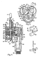
- the numeral 10 generally designates the improved orbital weld head tool of the invention.
- the tool 10 includes a mandrel 12 and workpiece feature engaging element 14 at the extreme projecting end thereof.
- the element 14 illustrated is for engagement of the interior wall of a steam generator tube.
- Equivalent feature engaging ends may be supplied, for example, in the form of an outwardly expanding, multi-fingered nozzle dam insert groove engaging element or a collet retainer for gripping a projecting workpiece feature such as a stud.
- the weld tip 16 is mounted on a conductive shoe 20 and, together with sheath member 18, is mounted for orbital rotation about the axis of mandrel 12 and reciprocation in a path parallel to said axis toward and away from a workpiece engaged by element 14.
- the tip 16, sheath member 18 and shoe 20 are all mounted in a insulative carriage 22 which surrounds mandrel 12 and moves back and forth and around it within the tool housing 46.
- a drive flange 24, belt pulley 26 and drive belt 28 provide relative rotation of the unit through ball bearing assembly 30.
- the ball bearing assembly 30 is conductive with a conductive lubricant and is as described in the aforementioned U.S. Patent Application Serial No. 028,997.
- An annular conductive bearing cup or body 32 is connected to a flexible gas and power supply hose 34 and reciprocates with carriage 22. Gas is communicated through longitudinal openings 36 and annular groove 37 in drive flange 24 from hose 34 to openings 38 in conductive shoe 20 and thence along weld tip 16 in concentric conduit 19.
- a hollow insulator 40 with a central opening is appropriately sealed by O-rings 42 to prevent gas leakage along mandrel 12.
- a nut 44 holds the mandrel in place in the end of body or housing 46.
- a top 48 is secured to body 46 by means of cap screws 50.
- a mounting plate 52 is provided to attach the tool 10 to a manipulator arm 54 of the type used for steam generator repairs in nuclear steam supply system maintenance to reduce worker exposure to radiation.
- the motors 62 and 64 are mounted for reciprocation with carriage 22.
- the motor 62 is the drive motor which has a drive pulley or pinion 66 for driving belt 28 to create rotation of the carriage.
- the motor 64 is the arc voltage control motor which reciprocates the carriage 22 and attendant structure, including portion 60 of tool 10, in response to the voltage of the arc as sensed by a conventional controller, not shown.
- the welding system used with the tool 10 is, typically, a three component system consisting of two "Centaur Model 75" welding power supplies and an arc voltage controller manufactured by DIMETRICS, Inc.
- Arc voltage sensing is accomplished by the controller which causes the drive motor 64 to advance and close the gap between the tungsten weld tip 16 and the workpiece engaged by electrically isolated mandrel 12 and element 14, or to retract and open the gap.
- This arc control technique is conventional to those skilled in the art.
- a stationary ball nut 70 under a ball nut cover 72, drives carriage 22 by means of ball and screw assembly 74.
- the ball and screw assembly is a "THOMSON Saginaw #5669420" and is conventional in the power transmission art.
- the motors 62 and 64 used in tool 10 may, typically, be those known as “T.R.W. Model A-1230".
- Reciprocation of the carriage 22 and attendant structure is sensed by limit switches such as switch 76, a "Grayhill #39-101".
- Rotation control is effected by limit switches of the type seen at 80 which engage a portion of rotating carriage 22.
- Switch 80 may be a "Micro Switch #311SX4-T”.
- An "Amphenol" connector 82 connects conductors from the switches to the welding controller and power supply apparatus (not shown).
Landscapes
- Engineering & Computer Science (AREA)
- Physics & Mathematics (AREA)
- Plasma & Fusion (AREA)
- Mechanical Engineering (AREA)
- Arc Welding In General (AREA)
- Pressure Welding/Diffusion-Bonding (AREA)
- Butt Welding And Welding Of Specific Article (AREA)
Applications Claiming Priority (2)
| Application Number | Priority Date | Filing Date | Title |
|---|---|---|---|
| US205399 | 1980-11-10 | ||
| US07/205,399 US4841118A (en) | 1987-03-23 | 1988-06-09 | Orbital weld head tool |
Publications (2)
| Publication Number | Publication Date |
|---|---|
| EP0345530A2 true EP0345530A2 (fr) | 1989-12-13 |
| EP0345530A3 EP0345530A3 (fr) | 1990-08-22 |
Family
ID=22762030
Family Applications (1)
| Application Number | Title | Priority Date | Filing Date |
|---|---|---|---|
| EP89109328A Withdrawn EP0345530A3 (fr) | 1988-06-09 | 1989-05-24 | Outil de tête pour le soudage orbital |
Country Status (4)
| Country | Link |
|---|---|
| US (1) | US4841118A (fr) |
| EP (1) | EP0345530A3 (fr) |
| JP (1) | JPH0225279A (fr) |
| KR (1) | KR900000153A (fr) |
Families Citing this family (9)
| Publication number | Priority date | Publication date | Assignee | Title |
|---|---|---|---|---|
| US5710403A (en) * | 1996-10-15 | 1998-01-20 | Jusionis; Vytautas John | Orbital weldhead with integral cooling |
| US20100013345A1 (en) * | 2006-06-26 | 2010-01-21 | Battelle Energy Alliance, Llc | Bi-metal coil |
| JP5582790B2 (ja) * | 2010-01-15 | 2014-09-03 | 三菱重工業株式会社 | 原子力施設で使用される溶接装置、先端工具案内装置および溶接方法 |
| US9969025B2 (en) | 2011-11-18 | 2018-05-15 | Lincoln Global, Inc. | System for mounting a tractor unit on a guide track |
| US9527153B2 (en) | 2013-03-14 | 2016-12-27 | Lincoln Global, Inc. | Camera and wire feed solution for orbital welder system |
| US9770775B2 (en) | 2013-11-11 | 2017-09-26 | Lincoln Global, Inc. | Orbital welding torch systems and methods with lead/lag angle stop |
| US9731385B2 (en) | 2013-11-12 | 2017-08-15 | Lincoln Global, Inc. | Orbital welder with wire height adjustment assembly |
| US9517524B2 (en) | 2013-11-12 | 2016-12-13 | Lincoln Global, Inc. | Welding wire spool support |
| EP3424635B1 (fr) * | 2017-07-05 | 2022-08-31 | Institute for Plasma Research | Procédé amélioré de fabrication d'une grille d'accélérateur activement refroidie par soudure à pénétration complète |
Family Cites Families (7)
| Publication number | Priority date | Publication date | Assignee | Title |
|---|---|---|---|---|
| GB1437787A (en) * | 1973-01-25 | 1976-06-03 | Clarke Chapman Ltd | Welding app'ratus |
| US3946191A (en) * | 1974-09-26 | 1976-03-23 | General Atomic Company | Welding apparatus |
| US3975616A (en) * | 1974-11-13 | 1976-08-17 | The Lincoln Electric Company | Control circuit for automatic electric arc-welder |
| US4262187A (en) * | 1978-08-24 | 1981-04-14 | Combustion Engineering, Inc. | System for plugging tubes by welding |
| US4359621A (en) * | 1980-07-14 | 1982-11-16 | Westinghouse Electric Corp. | Method for continuously welding a plurality of tubes disposed in multiple rows to a tube sheet |
| US4476367A (en) * | 1982-11-29 | 1984-10-09 | Gasparas Kazlauskas | Front face tube to tube sheet welding apparatus |
| SE441249B (sv) * | 1984-02-24 | 1985-09-23 | Esab Ab | Anordning for invendig svetsning av ett hornforband mellan ett forsta och ett andra ror |
-
1988
- 1988-06-09 US US07/205,399 patent/US4841118A/en not_active Expired - Fee Related
-
1989
- 1989-05-24 EP EP89109328A patent/EP0345530A3/fr not_active Withdrawn
- 1989-06-07 JP JP1143177A patent/JPH0225279A/ja active Pending
- 1989-06-08 KR KR1019890007838A patent/KR900000153A/ko not_active Ceased
Also Published As
| Publication number | Publication date |
|---|---|
| EP0345530A3 (fr) | 1990-08-22 |
| JPH0225279A (ja) | 1990-01-26 |
| US4841118A (en) | 1989-06-20 |
| KR900000153A (ko) | 1990-01-30 |
Similar Documents
| Publication | Publication Date | Title |
|---|---|---|
| EP1454698B1 (fr) | Appareil de changement automatique d'une extrémité d'outil de robot | |
| US4841118A (en) | Orbital weld head tool | |
| US5298710A (en) | Large bore welding apparatus | |
| EP0062996B1 (fr) | Tête de soudage orbitale à cassette | |
| US4527039A (en) | Method and apparatus for inner lining metallic bearing lugs | |
| GB1564180A (en) | Machines for welding abutting pipe pieces | |
| GB1576119A (en) | Orbital welding torch for the butt welding of tubes | |
| EP0173749A1 (fr) | Appareil perforateur ayant recours a un usinage par decharge electrique | |
| US4593849A (en) | Rotary welding device | |
| JPS6051950B2 (ja) | 自動溶接装置 | |
| US4791270A (en) | Gas tungsten arc welding machine with infinite rotating welding head and torch tilt | |
| CN116352226A (zh) | 手持式内壁全位置焊接氩弧堆焊机 | |
| US3594534A (en) | Welding apparatus | |
| EP0318639B1 (fr) | Outil d'usinage par étincelles | |
| US3632959A (en) | Exchangeable cartridge unit for automatic welders | |
| CA1049623A (fr) | Materiel pour souder un tube sur une plaque a tubes | |
| US6433307B1 (en) | Device for welding cylindrical workpieces | |
| US4804817A (en) | Bearing connector for rotary tool | |
| US4147920A (en) | Welding torch and supporting apparatus | |
| EP0295363B1 (fr) | Chalumeau rotatif | |
| RU2774713C1 (ru) | Автоматическое мобильное ротационное наплавочное устройство | |
| US3688071A (en) | Welding head with detachable power handle | |
| KR0126070B1 (ko) | 동관 자동용접장치 | |
| CN119457318A (zh) | 用于小直径螺纹孔内壁全位置增材修复的tig焊枪 | |
| JPH0421675Y2 (fr) |
Legal Events
| Date | Code | Title | Description |
|---|---|---|---|
| PUAI | Public reference made under article 153(3) epc to a published international application that has entered the european phase |
Free format text: ORIGINAL CODE: 0009012 |
|
| AK | Designated contracting states |
Kind code of ref document: A2 Designated state(s): BE ES FR SE |
|
| PUAL | Search report despatched |
Free format text: ORIGINAL CODE: 0009013 |
|
| STAA | Information on the status of an ep patent application or granted ep patent |
Free format text: STATUS: THE APPLICATION HAS BEEN WITHDRAWN |
|
| AK | Designated contracting states |
Kind code of ref document: A3 Designated state(s): BE ES FR SE |
|
| 18W | Application withdrawn |
Withdrawal date: 19900802 |