EP0345535A2 - Procédé de fabrication d'une tige de guidage trempée pour un guide linéaire - Google Patents
Procédé de fabrication d'une tige de guidage trempée pour un guide linéaire Download PDFInfo
- Publication number
- EP0345535A2 EP0345535A2 EP89109358A EP89109358A EP0345535A2 EP 0345535 A2 EP0345535 A2 EP 0345535A2 EP 89109358 A EP89109358 A EP 89109358A EP 89109358 A EP89109358 A EP 89109358A EP 0345535 A2 EP0345535 A2 EP 0345535A2
- Authority
- EP
- European Patent Office
- Prior art keywords
- guide shaft
- guide
- hardened
- shaft
- max
- Prior art date
- Legal status (The legal status is an assumption and is not a legal conclusion. Google has not performed a legal analysis and makes no representation as to the accuracy of the status listed.)
- Granted
Links
Images


Classifications
-
- F—MECHANICAL ENGINEERING; LIGHTING; HEATING; WEAPONS; BLASTING
- F16—ENGINEERING ELEMENTS AND UNITS; GENERAL MEASURES FOR PRODUCING AND MAINTAINING EFFECTIVE FUNCTIONING OF MACHINES OR INSTALLATIONS; THERMAL INSULATION IN GENERAL
- F16C—SHAFTS; FLEXIBLE SHAFTS; ELEMENTS OR CRANKSHAFT MECHANISMS; ROTARY BODIES OTHER THAN GEARING ELEMENTS; BEARINGS
- F16C29/00—Bearings for parts moving only linearly
- F16C29/005—Guide rails or tracks for a linear bearing, i.e. adapted for movement of a carriage or bearing body there along
-
- F—MECHANICAL ENGINEERING; LIGHTING; HEATING; WEAPONS; BLASTING
- F16—ENGINEERING ELEMENTS AND UNITS; GENERAL MEASURES FOR PRODUCING AND MAINTAINING EFFECTIVE FUNCTIONING OF MACHINES OR INSTALLATIONS; THERMAL INSULATION IN GENERAL
- F16C—SHAFTS; FLEXIBLE SHAFTS; ELEMENTS OR CRANKSHAFT MECHANISMS; ROTARY BODIES OTHER THAN GEARING ELEMENTS; BEARINGS
- F16C33/00—Parts of bearings; Special methods for making bearings or parts thereof
- F16C33/30—Parts of ball or roller bearings
- F16C33/58—Raceways; Race rings
- F16C33/64—Special methods of manufacture
Definitions
- the invention relates to a method for producing a hardened guide shaft for a linear guide, in particular for a linear guide with a guide slide provided with ball bushings, and a guide shaft produced thereafter.
- Linear guides are used to perform linear movements in many areas, such as in mechanical engineering, handling technology, fixture construction and precision engineering.
- Linear guides can be used, for example, as building blocks for grippers, robots, sliding tables, holders, measuring tools and the like.
- the core of the linear guide form one or two guide shafts, on which or on which a guide carriage is arranged, which is displaceable along the shaft or shafts. In reverse, however, the guide carriage can also remain stationary and the one or the two shafts are displaced.
- So-called ball bushings or linear ball bearings with a plurality of ball revolutions are generally arranged in the guide carriage for low-friction displacement and a high load capacity.
- the relative movement between the guide shaft and the guide slide arranged thereon can be achieved in various ways.
- Ball screws are known for this purpose, a spindle running parallel to the guide shaft and a spindle nut being arranged in the guide carriage. If the spindle is driven, the guide carriage moves accordingly.
- the present invention is therefore based on the object of creating a linear guide or a guide shaft for a linear guide which can be used very universally and by means of which a linear guide with a small size and high load capacity can be achieved.
- this object is achieved in that a toothing is introduced into a shaft over a partial circumferential area, after which the shaft is hardened with the teeth and then - as is known per se - is straightened and ground.
- a necessary part for the displacement between a guide shaft and a guide slide is now integrated in the guide shaft itself, namely a toothing.
- the counter member which is generally a pinion will arrange in the carriage.
- Other components - in addition to the usual drive device, such as a drive motor - are no longer necessary.
- the guide shaft thus performs a double function, which means that additional components can be omitted and at the same time a size reduction is achieved.
- the toothing can be a straight or a helical toothing.
- a very important further advantage of the invention is that in this way the drive base or guide shaft is supported and fastened at the same time, e.g. can be screwed. This creates a geometrically defined and vibration-free guideway that can withstand very high loads.
- any number of guide shafts can be arranged one behind the other, it being only necessary to ensure a smooth transition of the toothed section. In this way, practically linear guides of any length can be strung together. If a linear guide is designed with only one guide shaft, an anti-rotation lock, such as e.g. by grooving, molding or flattening the guide shaft.
- a sufficient hardness of the shaft which is particularly necessary for guide carriages with ball bushings, can be achieved in various ways.
- the shaft is inductively hardened with a round inductor, the magnetic flux being controlled in such a way that the magnetic flux in the region of the teeth is lower than in the rest of the region.
- the problems to be expected are surprisingly avoided.
- heat is supplied to a lesser extent in this area, but this is sufficient to bring the toothed area of the guide shaft to the desired hardness without disadvantageous overheating occurring.
- the toothing can advantageously be tough and thus better withstand jerky loads.
- the guide shaft to be hardened is at least approximately untwisted is pushed through the round inductor, and that the round inductor is provided in the non-toothed region of the guide shaft with the magnetic flux increasing parts or changes.
- the magnetic flux can be controlled in the desired manner by their corresponding arrangement and thus influence the hardness of the teeth in a targeted manner.
- inductively hardenable carbon steels with the following composition can be used: Carbon: 0.5 - 0.6% Silicon: 0.15 - 0.35% Manganese: 0.4 - 0.7% Phosphorus: Max. 0.025% Sulfur: Max. 0.035%. Such steels are listed in DIN 1712.
- rustproof and acid-resistant hardenable martensitic steels can be used for this.
- a possible material composition for this can have the following alloy components: Carbon: 0.85 - 0.95% Silicon: Max. 1 % Manganese: Max. 1 % Chrome: 17-19% Molybdenum: 0.9 - 1.3% Vanadium: 0.07 - 0.12% Phosphorus: Max. 0.045% Sulfur: Max. 0.030%.
- Rolling bearing steels, including stainless steel if necessary, are also possible for this purpose.
- the guide shaft can be subjected to a heat treatment before inductive hardening.
- the core and transition area of the guide shaft can be tempered in order to increase the core strength, which enables the shaft to be subjected to very high strength.
- the teeth of the toothing can be introduced before or after the tempering process, after which the inductive hardening process takes place. As a result of the previous remuneration, the core cross-section is significantly increased in its yield strength and strength.
- the arrangement of the toothed area of the guide shaft when installed in a linear guide can be any, which represents a further advantage of the invention.
- the drive device can thus always be optimally adapted to the existing conditions.
- an arrangement of the teeth on the top or on the side has the advantage that the guide shaft can be supported on the underside for high loads.
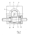
- the linear guide has a guide shaft 1, which is surrounded by a guide slide 2.
- a ball bushing 3 with a total of four ball revolutions 4 arranged around the circumference is arranged in the interior of the guide carriage 2.
- a sliding guide or a sliding bearing can of course also be provided for this.
- Solid or, of course, hollow shafts can be used as guide shafts, since the type and design of the guide shaft is fundamentally arbitrary for the invention.
- the guide shaft 1 is provided with transverse teeth 5 on approximately one fifth of its circumferential area.
- the width and the height of the teeth depend on the application.
- the size of the peripheral area in which the toothing is introduced into the guide shaft 1 is of course also dependent on the distance between the ball revolutions 4, since the toothing can only extend in the intermediate space.
- a pinion 6 is also fixed on a drive shaft 7.
- the drive shaft 7 is supported in ball bearings 8 and 9.
- a drive motor 10 (see FIG. 4) will be connected to the guide shaft 7 on one side and at the same time flanged to the guide carriage 2 on this side.
- the drive shaft 7 can of course also end in the guide carriage 2. However, if it is brought out on the opposite side, as in the exemplary embodiment shown in FIG. 1, a drive connection to a second guide shaft can be achieved, whereby a linear guide with two guide shafts 1 arranged at a distance from one another is achieved.
- FIG. 2 shows a principle representation of a linear guide similar to that in FIG. 1.
- the toothing 5 lies on the top of the guide shaft 1 or the guide shaft 1 is installed so that the teeth are on the top.
- the drive connection can take place in the same way as shown in FIG. 1, in which case only the ends of the drive shaft 7 protruding from the guide carriage 2 are shown.
- the advantage of this configuration is that the guide shaft 1 can be supported on the underside on a bearing block or a bearing rail 11 and can thus be supported. It is only necessary to provide a ball bushing 3 in the usual way, which is provided with a slot 12 on the underside.
- a third embodiment is shown, in which case the guide shaft 1 is installed so that the toothing 5 is arranged laterally and cooperates with a drive shaft 7 on which the pinion 6 is arranged, which has a vertical longitudinal axis.
- the guide shaft can also be supported on a bearing rail 11 in this way.
- the drive motor 10 for the drive is flanged on the top of the guide carriage 2 in this case.
- linear guides can be arranged in any manner and, in particular, can also be assembled in a modular manner.
- a such an embodiment is shown as an example in FIG. 4.
- each of the guide shafts 1A and 21A is provided with a toothing 5, a drive motor 10 in each case providing drive.
- the two guide shafts 1B and 21B have no separate drive and thus also no toothing 5.
- these two guide shafts can also each be driven by the same drive motor.
- the combined linear guide shown which enables movements in two axial directions, is stored in bearing 13.
- the guide carriages 2A, 2B and 22A and 22B are identical and also have connecting parts at the same locations (not shown). In this way, the guide carriages can be connected to one another as desired, which results in almost any possible combination.
- the guide shaft 5 can be manufactured in the following way:
- the transverse toothing 5 is e.g. ground in.
- the shaft can be tempered in the usual way beforehand, for this purpose it is heated, then quenched and finally tempered again until the desired tempering is achieved. This method is general prior art, which is why it is not explained in more detail here.
- the induction hardening process takes place in a round inductor through which the guide shaft to be hardened is pushed through without rotation.
- To control the magnetic flux are arranged over the circumference of the circular inductor laminations, which are shifted or arranged so that a higher magnetic flux and thus a higher temperature is generated in areas without teeth.
- the inductive hardening process itself is also generally known, which is why it is not described in detail here.
- Inductive surface hardening is a process in which a higher temperature is generated in a surface zone of the workpiece that is limited in depth and a local hardening is achieved by quenching the heated areas on the workpiece. Depending on the frequency, hardening depths of several millimeters can be generated.
- An induction system essentially consists of a frequency generator and a working device. In the frequency generator, the frequency of the supply network is converted into a single-phase alternating current of a higher frequency. The working device itself represents the actual inductor, which has to pick up the workpiece to be heated and has to carry out all the necessary movements.
- either the guide shaft is pushed through the inductor or the inductor is guided along the guide shaft.
- a steady movement of the inductor towards the stationary workpiece or vice versa enables a glow zone to be progressively created on the guide shaft.
- the water jet from a moving quench shower then continuously performs the hardening process.
- the hardening depths are adapted to the respective diameter range and also take into account, among other things, the surface pressures to be absorbed, for example, by linear linear ball bearings with different loads on the linear guide shaft wear or be exercised.
Landscapes
- Engineering & Computer Science (AREA)
- General Engineering & Computer Science (AREA)
- Mechanical Engineering (AREA)
- Manufacturing & Machinery (AREA)
- Heat Treatment Of Articles (AREA)
- Bearings For Parts Moving Linearly (AREA)
Applications Claiming Priority (2)
| Application Number | Priority Date | Filing Date | Title |
|---|---|---|---|
| DE3819279 | 1988-06-07 | ||
| DE3819279A DE3819279A1 (de) | 1988-06-07 | 1988-06-07 | Verfahren zur herstellung einer gehaerteten fuehrungswelle fuer eine linearfuehrung |
Publications (3)
| Publication Number | Publication Date |
|---|---|
| EP0345535A2 true EP0345535A2 (fr) | 1989-12-13 |
| EP0345535A3 EP0345535A3 (en) | 1990-11-28 |
| EP0345535B1 EP0345535B1 (fr) | 1993-08-11 |
Family
ID=6355996
Family Applications (1)
| Application Number | Title | Priority Date | Filing Date |
|---|---|---|---|
| EP89109358A Expired - Lifetime EP0345535B1 (fr) | 1988-06-07 | 1989-05-24 | Procédé de fabrication d'une tige de guidage trempée pour un guide linéaire |
Country Status (4)
| Country | Link |
|---|---|
| EP (1) | EP0345535B1 (fr) |
| CA (1) | CA1328986C (fr) |
| DE (2) | DE3819279A1 (fr) |
| ES (1) | ES2043950T3 (fr) |
Cited By (1)
| Publication number | Priority date | Publication date | Assignee | Title |
|---|---|---|---|---|
| WO2019094045A1 (fr) * | 2017-11-13 | 2019-05-16 | Hewlett-Packard Development Company, L.P. | Guides linéaires avec compensation thermique |
Families Citing this family (1)
| Publication number | Priority date | Publication date | Assignee | Title |
|---|---|---|---|---|
| CN108247304A (zh) * | 2018-01-12 | 2018-07-06 | 中国航发哈尔滨东安发动机有限公司 | 提升内花键热处理后齿向精度的方法 |
Family Cites Families (5)
| Publication number | Priority date | Publication date | Assignee | Title |
|---|---|---|---|---|
| DE1211674B (de) * | 1961-03-24 | 1966-03-03 | Siemens Ag | Vorrichtung zum Haerten von Zahnstangen |
| GB1036725A (en) * | 1962-05-05 | 1966-07-20 | Delapena & Sons Ltd | Improvements in or relating to induction heating |
| DD144794A1 (de) * | 1979-07-10 | 1980-11-05 | Waldemar Rohde | Gleichzeitiges induktionshaerten mehrerer haertezonen unterschiedlicher form |
| DE3212338C2 (de) * | 1981-04-03 | 1983-02-24 | M.A.N. Maschinenfabrik Augsburg-Nürnberg AG, 8900 Augsburg | Verfahren zur Herstellung von hochbelastbaren Maschinenteilen, insbesondere Brennkraftmaschinenteilen |
| GB2136529B (en) * | 1983-03-11 | 1986-04-09 | Cam Systems Limited | Linear actuator |
-
1988
- 1988-06-07 DE DE3819279A patent/DE3819279A1/de not_active Withdrawn
-
1989
- 1989-05-24 ES ES89109358T patent/ES2043950T3/es not_active Expired - Lifetime
- 1989-05-24 DE DE8989109358T patent/DE58905224D1/de not_active Expired - Fee Related
- 1989-05-24 EP EP89109358A patent/EP0345535B1/fr not_active Expired - Lifetime
- 1989-05-26 CA CA000600874A patent/CA1328986C/fr not_active Expired - Fee Related
Cited By (1)
| Publication number | Priority date | Publication date | Assignee | Title |
|---|---|---|---|---|
| WO2019094045A1 (fr) * | 2017-11-13 | 2019-05-16 | Hewlett-Packard Development Company, L.P. | Guides linéaires avec compensation thermique |
Also Published As
| Publication number | Publication date |
|---|---|
| CA1328986C (fr) | 1994-05-03 |
| ES2043950T3 (es) | 1994-01-01 |
| DE58905224D1 (de) | 1993-09-16 |
| EP0345535A3 (en) | 1990-11-28 |
| EP0345535B1 (fr) | 1993-08-11 |
| DE3819279A1 (de) | 1989-12-14 |
Similar Documents
| Publication | Publication Date | Title |
|---|---|---|
| DE602004012164T2 (de) | Horizontale fräsbohrmaschine mit mobiler säule | |
| DE112006001723B4 (de) | Rollführungsvorrichtung und Verfahren zum Herstellen derselben | |
| DE3688289T2 (de) | Beweglicher tisch. | |
| EP0218878B1 (fr) | Robot industriel du type à pont roulant | |
| DE2341046A1 (de) | Linearbewegungskugellager oder linearkugelfuehrung | |
| EP1286794B2 (fr) | Machine de laminage a froid | |
| EP3807023B1 (fr) | Machine de laminage à froid et procédé de génération d'un profil au niveau d'une pièce | |
| EP0345536B1 (fr) | Guide linéaire | |
| DE102008041952B4 (de) | Zahnstange | |
| DE8504018U1 (de) | Gleitgruppe für Arbeitsmaschinen | |
| EP0345535B1 (fr) | Procédé de fabrication d'une tige de guidage trempée pour un guide linéaire | |
| DE3004965C2 (fr) | ||
| DE10317318A1 (de) | Maschine zur Bearbeitung von Werkstücken, insbesondere von Kurbel- und Nockenwellen, mit mindestens einem Innen-Rundfräswerkzeug | |
| DE2218713A1 (de) | Keilnut-Fräsmaschine | |
| DE763225C (de) | Rollenlager | |
| EP1285722B1 (fr) | Perceuse radiale | |
| DE4037965C2 (de) | Verfahren zum Herstellen einer Lagerung eines Drehtisches | |
| DE3109198A1 (de) | Maschine zum fraesen von nuten in innenbohrungen von werkstuecken | |
| DE3224282A1 (de) | Linearkugellagereinheit | |
| DE102011002019A1 (de) | Verfahren zur Herstellung einer gehärteten Verzahnung | |
| AT514504B1 (de) | Zahnstange warm umgeformt mit Gewindenut | |
| DE871914C (de) | Einrichtung zur stufenweisen, insbesondere feinstufigen Regelung groesserer elektrischer Leistungen | |
| EP1171640A2 (fr) | Procede et dispositif pour durcir des surfaces de vilebrequin ou d'arbre a cames | |
| DE8624943U1 (de) | Teleskopartig ausfahrbare Handhabungs- oder Transporteinrichtung | |
| DE102018102095B3 (de) | Verfahren zum Herstellen von Funktionsflächen, insbesondere Verzahnungen, und nach diesem Verfahren hergestellte Funktionsflächen |
Legal Events
| Date | Code | Title | Description |
|---|---|---|---|
| PUAI | Public reference made under article 153(3) epc to a published international application that has entered the european phase |
Free format text: ORIGINAL CODE: 0009012 |
|
| AK | Designated contracting states |
Kind code of ref document: A2 Designated state(s): DE ES FR GB IT NL SE |
|
| PUAL | Search report despatched |
Free format text: ORIGINAL CODE: 0009013 |
|
| AK | Designated contracting states |
Kind code of ref document: A3 Designated state(s): DE ES FR GB IT NL SE |
|
| 17P | Request for examination filed |
Effective date: 19901112 |
|
| 17Q | First examination report despatched |
Effective date: 19920127 |
|
| GRAA | (expected) grant |
Free format text: ORIGINAL CODE: 0009210 |
|
| AK | Designated contracting states |
Kind code of ref document: B1 Designated state(s): DE ES FR GB IT NL SE |
|
| PG25 | Lapsed in a contracting state [announced via postgrant information from national office to epo] |
Ref country code: IT Free format text: LAPSE BECAUSE OF FAILURE TO SUBMIT A TRANSLATION OF THE DESCRIPTION OR TO PAY THE FEE WITHIN THE PRE;WARNING: LAPSES OF ITALIAN PATENTS WITH EFFECTIVE DATE BEFORE 2007 MAY HAVE OCCURRED AT ANY TIME BEFORE 2007. THE CORRECT EFFECTIVE DATE MAY BE DIFFERENT FROM THE ONE RECORDED.SCRIBED TIME-LIMIT Effective date: 19930811 |
|
| REF | Corresponds to: |
Ref document number: 58905224 Country of ref document: DE Date of ref document: 19930916 |
|
| GBT | Gb: translation of ep patent filed (gb section 77(6)(a)/1977) |
Effective date: 19931011 |
|
| ET | Fr: translation filed | ||
| REG | Reference to a national code |
Ref country code: ES Ref legal event code: FG2A Ref document number: 2043950 Country of ref document: ES Kind code of ref document: T3 |
|
| PLBE | No opposition filed within time limit |
Free format text: ORIGINAL CODE: 0009261 |
|
| STAA | Information on the status of an ep patent application or granted ep patent |
Free format text: STATUS: NO OPPOSITION FILED WITHIN TIME LIMIT |
|
| 26N | No opposition filed | ||
| EAL | Se: european patent in force in sweden |
Ref document number: 89109358.5 |
|
| REG | Reference to a national code |
Ref country code: GB Ref legal event code: 732E |
|
| REG | Reference to a national code |
Ref country code: FR Ref legal event code: TP |
|
| PGFP | Annual fee paid to national office [announced via postgrant information from national office to epo] |
Ref country code: GB Payment date: 20000509 Year of fee payment: 12 |
|
| PGFP | Annual fee paid to national office [announced via postgrant information from national office to epo] |
Ref country code: SE Payment date: 20000516 Year of fee payment: 12 |
|
| REG | Reference to a national code |
Ref country code: ES Ref legal event code: PC2A |
|
| PGFP | Annual fee paid to national office [announced via postgrant information from national office to epo] |
Ref country code: ES Payment date: 20000524 Year of fee payment: 12 Ref country code: FR Payment date: 20000524 Year of fee payment: 12 Ref country code: NL Payment date: 20000524 Year of fee payment: 12 |
|
| PGFP | Annual fee paid to national office [announced via postgrant information from national office to epo] |
Ref country code: DE Payment date: 20000527 Year of fee payment: 12 |
|
| PG25 | Lapsed in a contracting state [announced via postgrant information from national office to epo] |
Ref country code: GB Free format text: LAPSE BECAUSE OF NON-PAYMENT OF DUE FEES Effective date: 20010524 |
|
| PG25 | Lapsed in a contracting state [announced via postgrant information from national office to epo] |
Ref country code: ES Free format text: LAPSE BECAUSE OF NON-PAYMENT OF DUE FEES Effective date: 20010525 Ref country code: SE Free format text: LAPSE BECAUSE OF NON-PAYMENT OF DUE FEES Effective date: 20010525 |
|
| PG25 | Lapsed in a contracting state [announced via postgrant information from national office to epo] |
Ref country code: NL Free format text: LAPSE BECAUSE OF NON-PAYMENT OF DUE FEES Effective date: 20011201 |
|
| GBPC | Gb: european patent ceased through non-payment of renewal fee |
Effective date: 20010524 |
|
| PG25 | Lapsed in a contracting state [announced via postgrant information from national office to epo] |
Ref country code: FR Free format text: LAPSE BECAUSE OF NON-PAYMENT OF DUE FEES Effective date: 20020131 |
|
| NLV4 | Nl: lapsed or anulled due to non-payment of the annual fee |
Effective date: 20011201 |
|
| PG25 | Lapsed in a contracting state [announced via postgrant information from national office to epo] |
Ref country code: DE Free format text: LAPSE BECAUSE OF NON-PAYMENT OF DUE FEES Effective date: 20020301 |
|
| REG | Reference to a national code |
Ref country code: ES Ref legal event code: FD2A Effective date: 20030303 |