EP0345557A2 - Méthode et appareil pour régler le compactage lors de l'extrusion de parties composées de particules lignocellulosiques et liants - Google Patents
Méthode et appareil pour régler le compactage lors de l'extrusion de parties composées de particules lignocellulosiques et liants Download PDFInfo
- Publication number
- EP0345557A2 EP0345557A2 EP89109483A EP89109483A EP0345557A2 EP 0345557 A2 EP0345557 A2 EP 0345557A2 EP 89109483 A EP89109483 A EP 89109483A EP 89109483 A EP89109483 A EP 89109483A EP 0345557 A2 EP0345557 A2 EP 0345557A2
- Authority
- EP
- European Patent Office
- Prior art keywords
- pressure
- strands
- heating
- walls
- pressing
- Prior art date
- Legal status (The legal status is an assumption and is not a legal conclusion. Google has not performed a legal analysis and makes no representation as to the accuracy of the status listed.)
- Granted
Links
- 238000001125 extrusion Methods 0.000 title claims abstract description 23
- 238000000034 method Methods 0.000 title claims abstract description 15
- 239000000853 adhesive Substances 0.000 title 1
- 230000001070 adhesive effect Effects 0.000 title 1
- 238000005056 compaction Methods 0.000 title 1
- 239000002245 particle Substances 0.000 title 1
- 238000005192 partition Methods 0.000 claims abstract description 50
- 238000010438 heat treatment Methods 0.000 claims abstract description 49
- 238000007906 compression Methods 0.000 claims abstract description 16
- 230000006835 compression Effects 0.000 claims abstract description 15
- 238000001816 cooling Methods 0.000 claims abstract description 8
- 238000000465 moulding Methods 0.000 claims abstract description 8
- 239000011230 binding agent Substances 0.000 claims abstract description 7
- 239000007788 liquid Substances 0.000 claims abstract description 4
- 230000002093 peripheral effect Effects 0.000 claims 1
- 235000015927 pasta Nutrition 0.000 description 2
- 230000002411 adverse Effects 0.000 description 1
- 238000010276 construction Methods 0.000 description 1
- 230000007423 decrease Effects 0.000 description 1
- 239000003292 glue Substances 0.000 description 1
- 230000004048 modification Effects 0.000 description 1
- 238000012986 modification Methods 0.000 description 1
- 229920002379 silicone rubber Polymers 0.000 description 1
- 239000004945 silicone rubber Substances 0.000 description 1
- 239000007787 solid Substances 0.000 description 1
- 239000002023 wood Substances 0.000 description 1
Images


Classifications
-
- B—PERFORMING OPERATIONS; TRANSPORTING
- B30—PRESSES
- B30B—PRESSES IN GENERAL
- B30B11/00—Presses specially adapted for forming shaped articles from material in particulate or plastic state, e.g. briquetting presses, tabletting presses
- B30B11/22—Extrusion presses; Dies therefor
- B30B11/26—Extrusion presses; Dies therefor using press rams
-
- B—PERFORMING OPERATIONS; TRANSPORTING
- B27—WORKING OR PRESERVING WOOD OR SIMILAR MATERIAL; NAILING OR STAPLING MACHINES IN GENERAL
- B27N—MANUFACTURE BY DRY PROCESSES OF ARTICLES, WITH OR WITHOUT ORGANIC BINDING AGENTS, MADE FROM PARTICLES OR FIBRES CONSISTING OF WOOD OR OTHER LIGNOCELLULOSIC OR LIKE ORGANIC MATERIAL
- B27N3/00—Manufacture of substantially flat articles, e.g. boards, from particles or fibres
- B27N3/08—Moulding or pressing
- B27N3/28—Moulding or pressing characterised by using extrusion presses
-
- B—PERFORMING OPERATIONS; TRANSPORTING
- B30—PRESSES
- B30B—PRESSES IN GENERAL
- B30B11/00—Presses specially adapted for forming shaped articles from material in particulate or plastic state, e.g. briquetting presses, tabletting presses
- B30B11/22—Extrusion presses; Dies therefor
- B30B11/224—Extrusion chambers
Definitions
- the invention relates to a method and a device for controlling the compression during extrusion and extrusion tube pressing of small parts, in particular small plant parts, with binders, in which the filling and pressing chamber, and the cooling and molding channel, and the curing channel are divided longitudinally by partition walls are and form at least two or more filling and pressing rooms, optionally cooling and molding channels and curing channels.
- the output is correspondingly greater depending on the number of strands produced with such a device.
- the compression is known to be controlled by moving partitions and / or moving mandrels in extrusion molding.
- the invention has for its object strands of small parts, in particular small plant parts, with binders, independently or largely independent of their profile and wall thickness with a precisely controllable compression of greatest uniformity and - compared to the main application - with an increased by at least two or more times To generate output.
- the invention is based on the knowledge that non-longitudinally movable partitions, which protrude through the filling and pressing space and through the curing channel and form the side surfaces of the strands, at least in a direction transverse to the pressing direction, the same adjustable and controllable contact pressure on the outer surfaces the strands must exercise like the outer walls of the curing channel; but at least in the part of the curing channel in which the strands do not yet have sufficient dimensional stability due to insufficient binding of the binder of the small parts and want to swell.
- the invention therefore teaches to design the partitions in the filling and pressing space in such a way that their side walls abutting the forming strand fulfill the same geometric condition as the side walls of the filling and pressing space. If the filling and pressing space is shaped accordingly, the partitions narrow in a wedge shape from the end of the filling die and the hardening channel towards the end of the filling and pressing space. Each individual filling and pressing space formed by the partition walls thus fulfills the geometric conditions mentioned.
- the partition walls in relation to the frictional forces between them and the strands, perform the same function as the outer walls of the curing duct opposite them.
- the same, adjustable, variable and reproducible with each press stroke friction force is generated on the respective strand, as with the opposing outer walls of the curing channel set by clamping elements.
- the invention provides that the dividing walls consist of at least several, the friction on the Forming strands, and the heat required for curing to transfer into the strands to form walls.
- the partitions produce the same friction on the strands as the outer walls of the hardening duct, based on the time in the pressing cycle and the location in the length of the hardening duct, the strands of the same quality are produced as a single strand in a device without partitions.
- the walls of the partition walls are designed as cylinder bottoms with an intermediate pressure space.
- a temperature-resistant elastic element in which the printing surface of the printing medium is located, is installed pressure-tight between the walls, vulcanized or glued.
- the liquid heating medium can be used as the pressure medium generating the friction between the strands and the partition walls.
- the same specific pressure can be generated on the strands in the length of the curing channel as with the tensioning elements of the curing channel over its outer walls.
- the clamping elements in the length of the hardening channel are expediently dimensioned so that the size determining the frictional force - in hydraulic cylinders the pressure of the Medium, in the case of proportional magnets the tension is the same, even if the specific pressure on the strand is adapted to the length of the curing channel in accordance with its degree of setting and internal dimensional stability.
- the pressure spaces associated with the clamping elements are to be subdivided in accordance with the dimension and the position of the clamping elements in the length of the curing channel. If the pressure areas of the partition walls are the same in size, the pressure of the heating and pressure medium is adjusted according to the position of the associated clamping elements. If the printing areas are adjusted in size, the same pressure is applied to them.
- a closed circuit of the heating and pressure medium with a circulating pump must be used.
- a heat exchanger or a heater is provided, which heats the medium. If heat exchangers are used, the heat source that heats the curing duct can of course also be used for heating.
- an expansion tank is provided in the closed circuit, which compensates for changes in volume of the heating and pressure medium.
- This expansion tank is also designed according to the invention as a pressure generator, the power source of which is a hydraulic cylinder in the case of proportional magnetic clamping elements.
- the power source of the expansion tank for pressure in the closed circuit is to be translated in such a way that the quantity determining the power of the power source is identical to the power of the associated clamping elements; at Proportional magnets are the tension, in hydraulic cylinders the pressure.
- the partition walls are each formed with a plurality of pressure and heating rooms, the pressure and heating rooms lying in the same length in the curing channel of all the partition walls are to be designed as a closed circuit.
- the number of pressure and heating rooms in each partition determines the number of closed circuits with the associated elements.
- the specific pressure of the partition walls on the strands is kept the same as the pressure in the tensioning elements of the curing channel, although the force determining the power sources in is the same size for all power sources.
- the walls of the curing channel can be created by tensioning elements, as well as by closed pressure and heating circuits, which generate frictional forces on the strands.
- the partitions are also rigid up to the length from which the outer walls are set with clamping elements.
- the partitions are only leaned against the strands in such a way that the heat of the pressure and heating medium can be transferred into the strands without major gap losses.
- strands with different cross sections are produced at the same time with a device, it has proven to be advantageous not only to provide the walls of the partition walls placed on the strands by the pressure and heating medium, but also to provide a backup transversely to the pressing direction.
- Part of the walls is expediently designed to be longitudinally and transversely stable over the length of the curing channel, and the other part is only designed to be longitudinally stable — that is, it can be set transversely to the pressing direction by the pressure and heating medium. This ensures that the strands in the curing channel cannot deviate significantly from the pressing direction.
- extrusion tube presses with standing or moving and / or expandable mandrels are used.
- the pressure of the pressure and heating medium is only adapted to the degree of setting and the internal dimensional stability of the strands in the length of the curing channel.
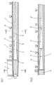
- Fig. 1 an extrusion device is shown in longitudinal section with a partially broken partition.
- the filling and pressing space 01 in which the small parts come from the filling shaft 02 , is closed by a closing element 04 during the pressing stroke of the pressing die 03 .
- the invention also includes filling and pressing rooms without closing elements 03 .
- the curing duct 05 with the clamping elements 06 connects to the filling and pressing chamber 01 .
- the partition 07 protrudes through the filling and pressing chamber 01 and curing channel 05 .
- the hardening duct Up to the beginning 08 of the hardening duct, it is rigid and provided in the hardening duct 05 with a pressure and heating chamber 09 , which is delimited by an elastic element 10 , which connects the walls 11 of the partition in a pressure-tight manner.
- the cross section 12 of the pressure and heating chamber 09 is formed in one piece in this example and adapted to the degree of hardening of the binder of the strand and its internal dimensional stability in the hardening channel 05 .
- Fig. 2 shows a longitudinal section through a curing channel 13 , which adjoins a filling and pressing chamber 14 .
- the partition 16 is divided into several pressure and heating rooms 17, 17 ', 17' lying in the length of the curing channel .
- the heating rooms 17 and 17 ' are of equal size in cross section and are different according to their position in the length of the curing channel 13 with different, the degree of curing channel 13 those, the degree of hardening of the strand and its internal dimensional stability, with correspondingly large pressures of the heating and pressure medium.
- the setting has already progressed so far and the internal dimensional stability of the strand is so great that the walls 18 of the partition wall 16 only have to be adjusted in such a way that the heat of the heating and pressure medium can be transferred without major gap losses.
- the cross sections of the pressure and heating rooms 17, 17 ' which can optionally also be designed as several pressure and heating rooms, are of different sizes, the pressure and heating rooms can be combined to form a closed circuit and subjected to the same pressure.
- the specific contact force on the strands is determined in such a way that it corresponds to the tensioning elements 19 belonging to the length of the hardening duct 13 .
- Fig. 3 shows a cross section on the line I - I through the filling and pressing chamber 20 of a three-strand extrusion device.
- the filling and pressing chamber 20 is closed by a closing slide 21 during the pressing stroke and separated from the inlet shafts 22 .
- the dividing walls 23 are rigid in the area of the filling and pressing space 20 and are not movably fastened to the boundary wall 24 therein.
- FIG. 4 shows a cross section through a hardening channel in which a rectangular strand 25 , a square strand 26 and a round strand 27 are hardened.
- the profiles of the strands 25, 26, 27 are adapted to the outer walls 28, 29, 30, 31 , the outer walls 28, 29, 30 being set against the strands 25, 26, 27 by tensioning elements 32 .
- the walls 33, 34, 35, 36 of the partitions 37, 38 are connected to one another by elastic elements 39, 40 .
- the pressure and heating medium circulates in the cavities 41, 42 .
- the compression of the strands 25, 26, 27 by means of the ram of the extrusion press is controlled by the pressure of the pressure and heating medium in the cavities 41, 42 of their surfaces and the force of the tensioning elements 32 .
- the forces acting on the strands are gem in the length of the curing channel, the degree of curing and in time in the pressing cycle of the desired compression. adapted to the main application.
- the outer walls 28, 29, 30, 31 can be heated, for example, by a liquid medium via the bores 43 .
- FIG. 5 shows a partial cross section through a hardening channel in which pencil halves are hardened from, for example, wood shavings.
- a rigid partition 44 is arranged next to an adjustable partition 45 , which results in a simpler construction.
- FIG. 6 shows a partial cross section through a curing channel in which wooden strands, for example pasta made from pasta, are cured.
- Partition 46 made in four adjustable walls 48 , which are connected to one another in a pressure-tight manner by elastic, temperature-resistant elements 47 , for example made of silicone rubber.
- the heating and the generation of the friction pressure on the strands 49 is carried out by the heating and pressure medium in the cavity 50 .
- the mandrels 51 which create the cavity of the strands 49 can be designed to be standing, moving or widening. From a corresponding size, the mandrels 51 are also to be heated.
- Fig. 7 shows a partial longitudinal section through an extrusion device.
- the filling and pressing chamber 52 the walls 53 of which run parallel here, is followed by a molding and cooling channel 54 with widening cross sections.
- the first rigid part 55 of the hardening duct 56 is likewise widened in a wedge shape.
- the adjoining part 57 of the curing channel can be designed as described.
Landscapes
- Engineering & Computer Science (AREA)
- Life Sciences & Earth Sciences (AREA)
- Mechanical Engineering (AREA)
- Manufacturing & Machinery (AREA)
- Wood Science & Technology (AREA)
- Forests & Forestry (AREA)
- Dry Formation Of Fiberboard And The Like (AREA)
- Moulding By Coating Moulds (AREA)
- Extrusion Moulding Of Plastics Or The Like (AREA)
Priority Applications (1)
| Application Number | Priority Date | Filing Date | Title |
|---|---|---|---|
| AT89109483T ATE104201T1 (de) | 1988-06-07 | 1989-05-26 | Verfahren und vorrichtung zur steuerung der verdichtung beim strang- und strangrohrpressen von kleinteilen, insbesondere aus pflanzlichen kleinteilen, mit bindemitteln. |
Applications Claiming Priority (2)
| Application Number | Priority Date | Filing Date | Title |
|---|---|---|---|
| DE3819382 | 1988-06-07 | ||
| DE19883819382 DE3819382A1 (de) | 1988-04-26 | 1988-06-07 | Verfahren und vorrichtung zur steuerung der verdichtung beim strang- u. strangrohrpressen von kleinteilen, insbes. aus pflanzl. kleinteilen, mit bindemitteln |
Publications (3)
| Publication Number | Publication Date |
|---|---|
| EP0345557A2 true EP0345557A2 (fr) | 1989-12-13 |
| EP0345557A3 EP0345557A3 (fr) | 1991-04-10 |
| EP0345557B1 EP0345557B1 (fr) | 1994-04-13 |
Family
ID=6356053
Family Applications (1)
| Application Number | Title | Priority Date | Filing Date |
|---|---|---|---|
| EP89109483A Expired - Lifetime EP0345557B1 (fr) | 1988-06-07 | 1989-05-26 | Méthode et appareil pour régler le compactage lors de l'extrusion de parties composées de particules lignocellulosiques et liants |
Country Status (3)
| Country | Link |
|---|---|
| EP (1) | EP0345557B1 (fr) |
| AT (1) | ATE104201T1 (fr) |
| DE (1) | DE58907432D1 (fr) |
Family Cites Families (2)
| Publication number | Priority date | Publication date | Assignee | Title |
|---|---|---|---|---|
| DE7525585U (de) * | 1975-08-12 | 1977-09-08 | Heggenstaller, Anton, 8891 Unterbernbach | Vorrichtung zum aushaerten stranggepresster koerper |
| DE3814082A1 (de) * | 1988-04-26 | 1989-11-09 | Karl Schedlbauer | Verfahren und vorrichtung zum steuern der verdichtung beim strangpressen von kleinteilen, insbesondere holzkleinteilen, mit bindemitteln |
-
1989
- 1989-05-26 AT AT89109483T patent/ATE104201T1/de not_active IP Right Cessation
- 1989-05-26 DE DE58907432T patent/DE58907432D1/de not_active Expired - Fee Related
- 1989-05-26 EP EP89109483A patent/EP0345557B1/fr not_active Expired - Lifetime
Also Published As
| Publication number | Publication date |
|---|---|
| ATE104201T1 (de) | 1994-04-15 |
| EP0345557A3 (fr) | 1991-04-10 |
| EP0345557B1 (fr) | 1994-04-13 |
| DE58907432D1 (de) | 1994-05-19 |
Similar Documents
| Publication | Publication Date | Title |
|---|---|---|
| DE3016926C2 (de) | Vorrichtung zum Aushärten stranggepreßter Körper | |
| DE69016210T2 (de) | Verfahren und vorrichtung zur verdichtung eines holzmusters. | |
| DE4234002A1 (de) | Verfahren und Vorrichtung zum Herstellen eines Faserverbundbauteils | |
| DE10354554A1 (de) | Vorrichtung zum Richten eines Rohres | |
| DE2535989C3 (de) | Vorrichtung zum Ausharten stranggepreßter Körper | |
| EP3368261A2 (fr) | Système de noyau, utilisation du système de noyau dans la fabrication d'un élément composite renforcé par fibres et procédé de fabrication d'un élément composite renforcé par fibres | |
| DE2461066A1 (de) | Schliesseinheit fuer eine spritzgussmaschine oder spritzpresse | |
| EP1066138B1 (fr) | Procede et dispositif permettant de fabriquer un materiau profile | |
| DE1258587B (de) | Verfahren und Vorrichtung zum Zusammendruecken zweier relativ zueinander bewegbarer Druckelemente | |
| EP0345557B1 (fr) | Méthode et appareil pour régler le compactage lors de l'extrusion de parties composées de particules lignocellulosiques et liants | |
| DE10245284A1 (de) | Verfahren und Vorrichtung zum Strang- und Strangrohrpressen von Kleinteilen, insbesondere Holzkleinteilen, z.B. für Palettenklötze | |
| DE3819382A1 (de) | Verfahren und vorrichtung zur steuerung der verdichtung beim strang- u. strangrohrpressen von kleinteilen, insbes. aus pflanzl. kleinteilen, mit bindemitteln | |
| EP0339497B1 (fr) | Procédé et dispositif pour extruder des tiges ou pour extruder des tubes | |
| DE3906107A1 (de) | Quadratische presse | |
| EP0339495A2 (fr) | Procédé et dispositif pour extruder des profils, en particulier pour extruder des tubes à partir d'un mélange de copeaux végétaux et de liants | |
| EP1198331B1 (fr) | Procede pour extruder des petites pieces vegetales | |
| DE3814099A1 (de) | Verfahren und vorrichtung zum strang- und stranrohrpressen von kleinteilen, insbesondere holzkleinteilen, mit bindemitteln | |
| DE19830542A1 (de) | Verfahren und Vorrichtung zur Leistungssteigerung, zur Verbesserung der Biegefestigkeit, der Steuerung der Verdichtung und zur Längsorientierung der Kleinteile beim Strang- und Strangrohrpressen von flächigen Kleinteilen | |
| DE3507293C2 (de) | Verfahren zur Festigkeitssteigerung von einwandigen rohrförmigen Bauteilen, sowie Vorrichtung zur Durchführung dieses Verfahrens | |
| AT522063B1 (de) | Druckpresse zum Herstellen eines Laminatbauteiles sowie Verfahren zum Pressen eines Laminatbauteiles | |
| DE3814082A1 (de) | Verfahren und vorrichtung zum steuern der verdichtung beim strangpressen von kleinteilen, insbesondere holzkleinteilen, mit bindemitteln | |
| DE10043030A1 (de) | Kurztaktpresse | |
| DE10316119A1 (de) | Verfahren und Vorrichtung zum Aushärten von Strängen aus Kleinteilen mit Bindemitteln nach einer Strangpresse | |
| DE10245285A1 (de) | Verfahren und Vorrichtung zur Verringerung des Pressdruckes und zur Steuerung der Verdichtung beim Strang- und Strangrohrpressen | |
| DE4443270C2 (de) | Verfahren zur Herstellung von Formteilen für Kaminrohre oder dergleichen und Presse zur Durchführung des Verfahrens |
Legal Events
| Date | Code | Title | Description |
|---|---|---|---|
| PUAI | Public reference made under article 153(3) epc to a published international application that has entered the european phase |
Free format text: ORIGINAL CODE: 0009012 |
|
| AK | Designated contracting states |
Kind code of ref document: A2 Designated state(s): AT BE CH DE ES FR GB GR IT LI LU NL SE |
|
| PUAL | Search report despatched |
Free format text: ORIGINAL CODE: 0009013 |
|
| PUAF | Information related to the publication of a search report (a3 document) modified or deleted |
Free format text: ORIGINAL CODE: 0009199SEPU |
|
| PUAL | Search report despatched |
Free format text: ORIGINAL CODE: 0009013 |
|
| AK | Designated contracting states |
Kind code of ref document: A3 Designated state(s): AT BE CH DE ES FR GB GR IT LI LU NL SE |
|
| D17D | Deferred search report published (deleted) | ||
| AK | Designated contracting states |
Kind code of ref document: A3 Designated state(s): AT BE CH DE ES FR GB GR IT LI LU NL SE |
|
| 17P | Request for examination filed |
Effective date: 19911009 |
|
| 17Q | First examination report despatched |
Effective date: 19921103 |
|
| GRAA | (expected) grant |
Free format text: ORIGINAL CODE: 0009210 |
|
| AK | Designated contracting states |
Kind code of ref document: B1 Designated state(s): AT BE CH DE ES FR GB GR IT LI LU NL SE |
|
| PG25 | Lapsed in a contracting state [announced via postgrant information from national office to epo] |
Ref country code: NL Effective date: 19940413 Ref country code: GR Free format text: LAPSE BECAUSE OF FAILURE TO SUBMIT A TRANSLATION OF THE DESCRIPTION OR TO PAY THE FEE WITHIN THE PRESCRIBED TIME-LIMIT Effective date: 19940413 Ref country code: ES Free format text: THE PATENT HAS BEEN ANNULLED BY A DECISION OF A NATIONAL AUTHORITY Effective date: 19940413 |
|
| REF | Corresponds to: |
Ref document number: 104201 Country of ref document: AT Date of ref document: 19940415 Kind code of ref document: T |
|
| RAP2 | Party data changed (patent owner data changed or rights of a patent transferred) |
Owner name: SCHEDLBAUER, KARL |
|
| PGFP | Annual fee paid to national office [announced via postgrant information from national office to epo] |
Ref country code: GB Payment date: 19940519 Year of fee payment: 6 |
|
| REF | Corresponds to: |
Ref document number: 58907432 Country of ref document: DE Date of ref document: 19940519 |
|
| PG25 | Lapsed in a contracting state [announced via postgrant information from national office to epo] |
Ref country code: AT Effective date: 19940526 |
|
| ITTA | It: last paid annual fee | ||
| PG25 | Lapsed in a contracting state [announced via postgrant information from national office to epo] |
Ref country code: LU Free format text: LAPSE BECAUSE OF NON-PAYMENT OF DUE FEES Effective date: 19940531 Ref country code: LI Effective date: 19940531 Ref country code: CH Effective date: 19940531 |
|
| GBT | Gb: translation of ep patent filed (gb section 77(6)(a)/1977) |
Effective date: 19940519 |
|
| ITF | It: translation for a ep patent filed | ||
| ET | Fr: translation filed | ||
| NLV1 | Nl: lapsed or annulled due to failure to fulfill the requirements of art. 29p and 29m of the patents act | ||
| EAL | Se: european patent in force in sweden |
Ref document number: 89109483.1 |
|
| REG | Reference to a national code |
Ref country code: CH Ref legal event code: PL |
|
| PLBE | No opposition filed within time limit |
Free format text: ORIGINAL CODE: 0009261 |
|
| STAA | Information on the status of an ep patent application or granted ep patent |
Free format text: STATUS: NO OPPOSITION FILED WITHIN TIME LIMIT |
|
| 26N | No opposition filed | ||
| PGFP | Annual fee paid to national office [announced via postgrant information from national office to epo] |
Ref country code: FR Payment date: 19950517 Year of fee payment: 7 |
|
| PGFP | Annual fee paid to national office [announced via postgrant information from national office to epo] |
Ref country code: SE Payment date: 19950523 Year of fee payment: 7 |
|
| PG25 | Lapsed in a contracting state [announced via postgrant information from national office to epo] |
Ref country code: GB Effective date: 19950526 |
|
| PGFP | Annual fee paid to national office [announced via postgrant information from national office to epo] |
Ref country code: DE Payment date: 19950601 Year of fee payment: 7 |
|
| PGFP | Annual fee paid to national office [announced via postgrant information from national office to epo] |
Ref country code: BE Payment date: 19950609 Year of fee payment: 7 |
|
| GBPC | Gb: european patent ceased through non-payment of renewal fee |
Effective date: 19950526 |
|
| PG25 | Lapsed in a contracting state [announced via postgrant information from national office to epo] |
Ref country code: SE Effective date: 19960527 |
|
| PG25 | Lapsed in a contracting state [announced via postgrant information from national office to epo] |
Ref country code: BE Effective date: 19960531 |
|
| BERE | Be: lapsed |
Owner name: SCHEDLBAUER KARL Effective date: 19960531 |
|
| PG25 | Lapsed in a contracting state [announced via postgrant information from national office to epo] |
Ref country code: FR Effective date: 19970131 |
|
| PG25 | Lapsed in a contracting state [announced via postgrant information from national office to epo] |
Ref country code: DE Effective date: 19970201 |
|
| EUG | Se: european patent has lapsed |
Ref document number: 89109483.1 |
|
| REG | Reference to a national code |
Ref country code: FR Ref legal event code: ST |
|
| PG25 | Lapsed in a contracting state [announced via postgrant information from national office to epo] |
Ref country code: IT Free format text: LAPSE BECAUSE OF NON-PAYMENT OF DUE FEES;WARNING: LAPSES OF ITALIAN PATENTS WITH EFFECTIVE DATE BEFORE 2007 MAY HAVE OCCURRED AT ANY TIME BEFORE 2007. THE CORRECT EFFECTIVE DATE MAY BE DIFFERENT FROM THE ONE RECORDED. Effective date: 20050526 |