EP0345561A2 - Dispositif téléscopique ainsi que procédé pour sa fabrication - Google Patents
Dispositif téléscopique ainsi que procédé pour sa fabrication Download PDFInfo
- Publication number
- EP0345561A2 EP0345561A2 EP89109512A EP89109512A EP0345561A2 EP 0345561 A2 EP0345561 A2 EP 0345561A2 EP 89109512 A EP89109512 A EP 89109512A EP 89109512 A EP89109512 A EP 89109512A EP 0345561 A2 EP0345561 A2 EP 0345561A2
- Authority
- EP
- European Patent Office
- Prior art keywords
- piston
- slide ring
- ring
- shoulders
- ptfe
- Prior art date
- Legal status (The legal status is an assumption and is not a legal conclusion. Google has not performed a legal analysis and makes no representation as to the accuracy of the status listed.)
- Withdrawn
Links
Images

Classifications
-
- F—MECHANICAL ENGINEERING; LIGHTING; HEATING; WEAPONS; BLASTING
- F16—ENGINEERING ELEMENTS AND UNITS; GENERAL MEASURES FOR PRODUCING AND MAINTAINING EFFECTIVE FUNCTIONING OF MACHINES OR INSTALLATIONS; THERMAL INSULATION IN GENERAL
- F16J—PISTONS; CYLINDERS; SEALINGS
- F16J15/00—Sealings
- F16J15/16—Sealings between relatively-moving surfaces
- F16J15/32—Sealings between relatively-moving surfaces with elastic sealings, e.g. O-rings
-
- F—MECHANICAL ENGINEERING; LIGHTING; HEATING; WEAPONS; BLASTING
- F16—ENGINEERING ELEMENTS AND UNITS; GENERAL MEASURES FOR PRODUCING AND MAINTAINING EFFECTIVE FUNCTIONING OF MACHINES OR INSTALLATIONS; THERMAL INSULATION IN GENERAL
- F16F—SPRINGS; SHOCK-ABSORBERS; MEANS FOR DAMPING VIBRATION
- F16F9/00—Springs, vibration-dampers, shock-absorbers, or similarly-constructed movement-dampers using a fluid or the equivalent as damping medium
- F16F9/32—Details
- F16F9/3207—Constructional features
- F16F9/3214—Constructional features of pistons
-
- F—MECHANICAL ENGINEERING; LIGHTING; HEATING; WEAPONS; BLASTING
- F16—ENGINEERING ELEMENTS AND UNITS; GENERAL MEASURES FOR PRODUCING AND MAINTAINING EFFECTIVE FUNCTIONING OF MACHINES OR INSTALLATIONS; THERMAL INSULATION IN GENERAL
- F16J—PISTONS; CYLINDERS; SEALINGS
- F16J1/00—Pistons; Trunk pistons; Plungers
- F16J1/02—Bearing surfaces
-
- F—MECHANICAL ENGINEERING; LIGHTING; HEATING; WEAPONS; BLASTING
- F05—INDEXING SCHEMES RELATING TO ENGINES OR PUMPS IN VARIOUS SUBCLASSES OF CLASSES F01-F04
- F05C—INDEXING SCHEME RELATING TO MATERIALS, MATERIAL PROPERTIES OR MATERIAL CHARACTERISTICS FOR MACHINES, ENGINES OR PUMPS OTHER THAN NON-POSITIVE-DISPLACEMENT MACHINES OR ENGINES
- F05C2225/00—Synthetic polymers, e.g. plastics; Rubber
- F05C2225/04—PTFE [PolyTetraFluorEthylene]
Definitions
- the invention relates to a telescopic device, in particular a shock absorber, with a cylinder tube and a piston axially displaceable therein, on the circumferential surface of which a sliding ring made of a PTFE material is arranged, which bears against shoulders to prevent axial movement and comes into contact with the inner wall of the cylinder tube stands.
- the invention further relates to a method for producing a telescopic device, in which a slide ring is formed from PTFE and placed around the piston in contact with shoulders.
- Devices consisting of a cylinder tube and a piston are used in various forms in hydraulics and pneumatics.
- a telescopic cylinder with a piston rod attached to the piston and protruding from the cylinder tube, such devices are used in particular as dampers or as hydraulically or pneumatically operated pressure cylinders.
- the pistons of such telescopic cylinders are often provided on their peripheral surfaces with slide rings, by means of which the piston can be supported on the inner wall of the cylinder tube.
- the slide rings also have a sealing function.
- PTFE Polytetrafluoroethylene - abbreviated PTFE - has proven to be a particularly suitable material for such sliding rings, since it is very chemically stable and also has low sliding values with only a very low stick-slip effect.
- PTFE materials are not only to be understood as those which consist of pure PTFE, but also modified PTFE which contains various admixtures, such as in particular carbon or metals. The admixtures can be above 50%, especially with metals. Nevertheless, a modified PTFE material is also used in such cases.
- the piston has a circumferential, wide annular groove on its circumferential surface, into which a finite strip of PTFE material is inserted. Its thickness is dimensioned in relation to the depth of the annular groove so that the slide ring formed from the strip protrudes over the circumferential surface of the piston. The end faces overlap in a step-like manner at the joint.
- the object of the invention is to design the combination of piston and slide ring in a device of the type mentioned at the outset in such a way that, despite substantially lower production costs, the seal and sliding conditions remain constant over the circumference are guaranteed, and to provide a method for producing this device.
- the slide ring is endless and includes the piston with radial shrinkage. Because of its endless design, the device according to the invention is characterized by sealing and sliding conditions which remain constant over the circumference. The radially inward shrink tension also ensures a firm hold of the slide ring.
- the shoulders against which the slide ring bears in order to prevent axial movement are formed by at least one ring-shaped projection which the slide ring surrounds in a form-fitting manner.
- This embodiment has the advantage in particular when the piston is made from sintered metal that the piston does not require any machining post-processing, since the projection can already be provided during the shaping of the piston. This is not possible, for example, in the case of ring grooves in which sliding rings are inserted. Accordingly, the manufacturing cost is low.
- the projection is designed as a cylindrical piston section and the slide ring has a U-shape with inwardly directed edge webs.
- This embodiment has proven to be particularly simple in terms of production technology.
- the thickness of the slide ring can be adapted to the respective conditions. A thickness of 0.5 to 1 mm has proven itself for dampers. It should the annular projection should protrude at least 0.8 mm.
- the shoulders can also be formed as part of a groove into which the slide ring is fitted.
- This embodiment is also characterized by low manufacturing costs because the slide ring is relatively easy to manufacture.
- the slide ring in this embodiment has a particularly good hold on the piston and thus ensures tightness even in difficult applications.
- the circumference of the slide ring can be determined so precisely that even manufacturing tolerances of the cylinder tube and / or the groove in the piston can be compensated.
- the method according to the invention is characterized in that an endless slide ring is formed, the inside diameter of which is at least in a partial area smaller than the associated contact ring surface on the piston, that the slide ring is then pulled axially onto the piston with simultaneous plastic widening until it has the intended axial Has reached the end position, and that it is then compressed radially inwards.
- the slide ring should be machined from a blank previously cut from a PTFE tube.
- the memory effect inherent in the PTFE material is used.
- the slide ring is produced in an endless form, in such a way that its inside diameter is smaller than that of the associated contact ring surface on the piston.
- the slide ring is then stretched over the piston by means of a calibration tool in such a way that it over the edge webs delimiting the groove or over the annular projection can be pushed over.
- the slide ring is compressed radially, for example by means of a press ring.
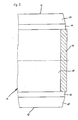
- Figure (1) shows an axial section of a piston (1) which is intended for a telescopic cylinder and is provided there for an axially displaceable bearing ring in a cylinder tube. It has flat front and back sides (2, 3) and a cylindrical peripheral surface (4). In the middle it has a through hole (5) extending in the axial direction, into which the end of a piston rod is inserted and which can be fastened with the piston (1).
- the peripheral surface (4) is stepped in such a way that a cylindrical projection (6) results which extends over the entire peripheral surface (4).
- a sliding ring (7) is placed over this projection, which in the cross section shown has a U shape with on both end faces has inner webs (8, 9).
- the edge webs (8, 9) lie on the end faces of the projection (6) and hold the slide ring (7) axially immovably on the projection (6).
- the slide ring (6) is made of a PTFE material with 25% carbon. Of course, other materials may also have been added to the PTFE material. It is initially made so that it has a radial undersize, i.e. H. its diameter is initially smaller than that of the corresponding sections of the peripheral surface (4). To slip on, the slide ring (7) is widened accordingly using a calibration tool so that it can be pushed over the projection. After being slipped on, the slide ring (7) is compressed again with a press ring. This compression initiates a memory effect of the PTFE material, so that the slide ring (7) tends to shrink back to its original shape, and in this way it lies against the circumferential surface (4 ) at. This gives the slide ring (7) a firm hold on the piston (1). It is characterized by high dimensional stability, low friction values, resistance to chemical influences and temperature resistance.
- Figure (2) shows an axial section of a piston (11) which is intended for a telescopic cylinder and is provided there for axially displaceable mounting in a cylinder tube. It has flat front and rear sides (12, 13) to which each inclined truncated cone surface (14, 15) connects. These merge into edge webs (16, 17) which delimit a flat and wide groove (18).
- the slide ring (19) is made as an endless ring. He initially has a radial undersize, i.e. its inside diameter is initially less than the inside diameter of the groove (18). So that the slide ring (19) can be pushed over the edge webs (16, 17), it is expanded using a calibration tool. If it is then in the groove (18), it is compressed again with a press ring, i.e. compressed inside. A memory effect of the PTFE material is initiated by this compression, so that the slide ring (19) endeavors to shrink back into its original shape. The result of this is that it rests against the wall of the groove (18) with a radially inward bias. This gives the slide ring (19) a firm hold on the piston (11).
Landscapes
- Engineering & Computer Science (AREA)
- General Engineering & Computer Science (AREA)
- Mechanical Engineering (AREA)
- Chemical & Material Sciences (AREA)
- Combustion & Propulsion (AREA)
- Pistons, Piston Rings, And Cylinders (AREA)
- Fluid-Damping Devices (AREA)
Applications Claiming Priority (4)
| Application Number | Priority Date | Filing Date | Title |
|---|---|---|---|
| DE8807324U | 1988-06-04 | ||
| DE8807324U DE8807324U1 (de) | 1988-06-04 | 1988-06-04 | Vorrichtung, insbesondere Teleskopzylinder |
| DE8814123U DE8814123U1 (de) | 1988-11-11 | 1988-11-11 | Teleskopierende Vorrichtung |
| DE8814123U | 1988-11-11 |
Publications (2)
| Publication Number | Publication Date |
|---|---|
| EP0345561A2 true EP0345561A2 (fr) | 1989-12-13 |
| EP0345561A3 EP0345561A3 (fr) | 1990-09-19 |
Family
ID=25953135
Family Applications (1)
| Application Number | Title | Priority Date | Filing Date |
|---|---|---|---|
| EP19890109512 Withdrawn EP0345561A3 (fr) | 1988-06-04 | 1989-05-26 | Dispositif téléscopique ainsi que procédé pour sa fabrication |
Country Status (1)
| Country | Link |
|---|---|
| EP (1) | EP0345561A3 (fr) |
Cited By (8)
| Publication number | Priority date | Publication date | Assignee | Title |
|---|---|---|---|---|
| EP0486402A1 (fr) * | 1990-11-15 | 1992-05-20 | Compagnie Plastic Omnium | Piston composite et son procédé de réalisation |
| DE4410996C1 (de) * | 1994-03-30 | 1995-06-01 | Fichtel & Sachs Ag | Schwingungsdämpfer |
| DE19707633C1 (de) * | 1997-02-26 | 1998-07-09 | Mannesmann Sachs Ag | Dichtung zwischen zwei axialen Bauteilen |
| WO2000022317A1 (fr) * | 1998-10-14 | 2000-04-20 | Gkn Sinter Metals Gmbh | Piston avec nervures d'appui pour ensemble piston-cylindre, en particulier piston amortisseur |
| WO2000022318A1 (fr) * | 1998-10-14 | 2000-04-20 | Gkn Sinter Metals Gmbh | Piston a effet d'etancheite dependant de la pression pour ensemble piston-cylindre, en particulier piston amortisseur |
| WO2000022319A1 (fr) * | 1998-10-14 | 2000-04-20 | Gkn Sinter Metals Gmbh | Piston pour ensemble piston-cylindre, en particulier piston amortisseur |
| US6928923B2 (en) | 2001-02-21 | 2005-08-16 | Gkn Sinter Metals Gmbh | Piston with supporting connector elements for a piston-cylinder arrangement, in particular a shock absorber piston |
| DE102007036017A1 (de) * | 2007-07-30 | 2009-02-19 | Gkn Sinter Metals Holding Gmbh | Kolben für eine Kolben-Zylinder-Anordnung und Herstellungsverfahren |
Family Cites Families (8)
| Publication number | Priority date | Publication date | Assignee | Title |
|---|---|---|---|---|
| FR995019A (fr) * | 1949-07-15 | 1951-11-26 | Perfectionnements aux amortisseurs de suspension hydrauliques à action directe | |
| GB756460A (en) * | 1953-11-12 | 1956-09-05 | Boulton Aircraft Ltd | Improvements in or relating to sealing rings for use between relatively movable members |
| DE1860858U (de) * | 1960-10-19 | 1962-10-25 | Auto Union Gmbh | Stossdaempfer. |
| FR1375013A (fr) * | 1963-04-18 | 1964-10-16 | Procédé d'utilisation de matrice plastique par le revêtement des pistons et des cylindres ainsi que pour la réalisation de segments | |
| JPS6088222A (ja) * | 1983-10-21 | 1985-05-18 | Daido Metal Kogyo Kk | 複合摺動体 |
| DE3429474A1 (de) * | 1984-08-10 | 1986-02-20 | Fichtel & Sachs Ag, 8720 Schweinfurt | Kolben mit einem kolbenring fuer schwingungsdaempfer oder federbeine |
| DE8807324U1 (de) * | 1988-06-04 | 1988-08-18 | Fietz, Manfred, 51399 Burscheid | Vorrichtung, insbesondere Teleskopzylinder |
| DE8814123U1 (de) * | 1988-11-11 | 1988-12-29 | Fietz, Manfred, 5093 Burscheid | Teleskopierende Vorrichtung |
-
1989
- 1989-05-26 EP EP19890109512 patent/EP0345561A3/fr not_active Withdrawn
Cited By (15)
| Publication number | Priority date | Publication date | Assignee | Title |
|---|---|---|---|---|
| EP0486402A1 (fr) * | 1990-11-15 | 1992-05-20 | Compagnie Plastic Omnium | Piston composite et son procédé de réalisation |
| FR2669392A1 (fr) * | 1990-11-15 | 1992-05-22 | Plastic Omnium Cie | Piston et son procede de realisation. |
| DE4410996C1 (de) * | 1994-03-30 | 1995-06-01 | Fichtel & Sachs Ag | Schwingungsdämpfer |
| US5615756A (en) * | 1994-03-30 | 1997-04-01 | Fichtel & Sachs Ag | Shock absorber for a motor vehicle, which shock absorber has a piston valve |
| DE19707633C1 (de) * | 1997-02-26 | 1998-07-09 | Mannesmann Sachs Ag | Dichtung zwischen zwei axialen Bauteilen |
| FR2761443A1 (fr) | 1997-02-26 | 1998-10-02 | Mannesmann Sachs Ag | Joint entre deux composants axialement mobiles l'un par rapport a l'autre |
| WO2000022317A1 (fr) * | 1998-10-14 | 2000-04-20 | Gkn Sinter Metals Gmbh | Piston avec nervures d'appui pour ensemble piston-cylindre, en particulier piston amortisseur |
| WO2000022318A1 (fr) * | 1998-10-14 | 2000-04-20 | Gkn Sinter Metals Gmbh | Piston a effet d'etancheite dependant de la pression pour ensemble piston-cylindre, en particulier piston amortisseur |
| WO2000022319A1 (fr) * | 1998-10-14 | 2000-04-20 | Gkn Sinter Metals Gmbh | Piston pour ensemble piston-cylindre, en particulier piston amortisseur |
| US6481336B2 (en) | 1998-10-14 | 2002-11-19 | Gkn Sinter Metals Gmbh | Piston with pressure-dependent sealing effect for a piston-cylinder arrangement, in particular a shock absorber piston |
| US6591948B2 (en) | 1998-10-14 | 2003-07-15 | Gkn Sinter Metals Gmbh | Piston with support webs for a piston-cylinder arrangement, in particular a shock absorber piston |
| US7178237B2 (en) | 1998-10-14 | 2007-02-20 | Gkn Sinter Metals Gmbh | Piston for a piston-cylinder arrangement, in particular a shock absorber piston |
| US6928923B2 (en) | 2001-02-21 | 2005-08-16 | Gkn Sinter Metals Gmbh | Piston with supporting connector elements for a piston-cylinder arrangement, in particular a shock absorber piston |
| DE102007036017A1 (de) * | 2007-07-30 | 2009-02-19 | Gkn Sinter Metals Holding Gmbh | Kolben für eine Kolben-Zylinder-Anordnung und Herstellungsverfahren |
| US8104174B2 (en) | 2007-07-30 | 2012-01-31 | Gkn Sinter Metals Holding Gmbh | Method for producing a piston |
Also Published As
| Publication number | Publication date |
|---|---|
| EP0345561A3 (fr) | 1990-09-19 |
Similar Documents
| Publication | Publication Date | Title |
|---|---|---|
| DE2905867C2 (de) | Dichtungsvorrichtung | |
| DE68904510T2 (de) | Metalldichtung fuer sehr hohen druck. | |
| DE2045528A1 (de) | Verbindungseinrichtung fur Stirnwand und Mantel eines Fluidzyhndergehauses | |
| DE1900113A1 (de) | Pendellager und Verfahren zu seiner Herstellung | |
| DE10135588A1 (de) | Lagerring | |
| DE4032921A1 (de) | Hochleistungsgasdruckfeder | |
| EP0345561A2 (fr) | Dispositif téléscopique ainsi que procédé pour sa fabrication | |
| DE8236692U1 (de) | Dichtungsanordnung zur gelenkigen verbindung von zwei rohrleitungen, insbesondere heissgehenden abgasleitungen | |
| DE19504207C5 (de) | Arbeitszylinder | |
| DE19841830A1 (de) | Reibungsarme Dichtung | |
| EP0380749B1 (fr) | Joint mécanique | |
| DE2951500A1 (de) | Dichtung in einem anpasstueck fuer vorhandene dichtnuten | |
| EP0052689A1 (fr) | Joint d'étanchéité pour tiges ou pistons | |
| EP0446448A1 (fr) | Dispositif d'assemblage pour tuyaux sous pression ou équivalents | |
| DE69611891T2 (de) | Hydraulische Kraftfahrzeug-Kupplungsbetätigung eingliedernd einen Zylinder mit einem metallischen Kolben | |
| DE20221504U1 (de) | Pressfitting für Rohre | |
| EP0117504A2 (fr) | Sortie pour éléments de construction sanitaires tels que lavabos, éviers, bains ou similaires | |
| DE3731177C2 (fr) | ||
| DE102019211385A1 (de) | Schwingungsdämpfer mit einem hydraulischen Endanschlag | |
| DE2227042B2 (de) | Dichtungsanordnung | |
| DE2432181B2 (de) | Dichtungsanordnung | |
| DE2004117A1 (de) | Anordnung an einem Teleskopzylinder | |
| DE1958563B2 (de) | Thermostatisches betaetigungselement | |
| DE4129892A1 (de) | Axialkolbenmaschine mit gleitring | |
| DE19728457B4 (de) | Hydraulisch spannbares Element zum kraftschlüssigen Verbinden eines zylindrischen Bauteils mit einem dazu konzentrisch angeordneten Körper |
Legal Events
| Date | Code | Title | Description |
|---|---|---|---|
| PUAI | Public reference made under article 153(3) epc to a published international application that has entered the european phase |
Free format text: ORIGINAL CODE: 0009012 |
|
| AK | Designated contracting states |
Kind code of ref document: A2 Designated state(s): DE ES FR GB IT SE |
|
| PUAL | Search report despatched |
Free format text: ORIGINAL CODE: 0009013 |
|
| AK | Designated contracting states |
Kind code of ref document: A3 Designated state(s): DE ES FR GB IT SE |
|
| STAA | Information on the status of an ep patent application or granted ep patent |
Free format text: STATUS: THE APPLICATION IS DEEMED TO BE WITHDRAWN |
|
| 18D | Application deemed to be withdrawn |
Effective date: 19910320 |