EP0345604A2 - Sanitäres Ventil - Google Patents
Sanitäres Ventil Download PDFInfo
- Publication number
- EP0345604A2 EP0345604A2 EP89109730A EP89109730A EP0345604A2 EP 0345604 A2 EP0345604 A2 EP 0345604A2 EP 89109730 A EP89109730 A EP 89109730A EP 89109730 A EP89109730 A EP 89109730A EP 0345604 A2 EP0345604 A2 EP 0345604A2
- Authority
- EP
- European Patent Office
- Prior art keywords
- valve
- spindle
- valve body
- movable
- stationary
- Prior art date
- Legal status (The legal status is an assumption and is not a legal conclusion. Google has not performed a legal analysis and makes no representation as to the accuracy of the status listed.)
- Withdrawn
Links
Images


Classifications
-
- F—MECHANICAL ENGINEERING; LIGHTING; HEATING; WEAPONS; BLASTING
- F16—ENGINEERING ELEMENTS AND UNITS; GENERAL MEASURES FOR PRODUCING AND MAINTAINING EFFECTIVE FUNCTIONING OF MACHINES OR INSTALLATIONS; THERMAL INSULATION IN GENERAL
- F16K—VALVES; TAPS; COCKS; ACTUATING-FLOATS; DEVICES FOR VENTING OR AERATING
- F16K11/00—Multiple-way valves, e.g. mixing valves; Pipe fittings incorporating such valves
- F16K11/10—Multiple-way valves, e.g. mixing valves; Pipe fittings incorporating such valves with two or more closure members not moving as a unit
-
- F—MECHANICAL ENGINEERING; LIGHTING; HEATING; WEAPONS; BLASTING
- F16—ENGINEERING ELEMENTS AND UNITS; GENERAL MEASURES FOR PRODUCING AND MAINTAINING EFFECTIVE FUNCTIONING OF MACHINES OR INSTALLATIONS; THERMAL INSULATION IN GENERAL
- F16K—VALVES; TAPS; COCKS; ACTUATING-FLOATS; DEVICES FOR VENTING OR AERATING
- F16K3/00—Gate valves or sliding valves, i.e. cut-off apparatus with closing members having a sliding movement along the seat for opening and closing
- F16K3/02—Gate valves or sliding valves, i.e. cut-off apparatus with closing members having a sliding movement along the seat for opening and closing with flat sealing faces; Packings therefor
- F16K3/04—Gate valves or sliding valves, i.e. cut-off apparatus with closing members having a sliding movement along the seat for opening and closing with flat sealing faces; Packings therefor with pivoted closure members
- F16K3/06—Gate valves or sliding valves, i.e. cut-off apparatus with closing members having a sliding movement along the seat for opening and closing with flat sealing faces; Packings therefor with pivoted closure members in the form of closure plates arranged between supply and discharge passages
- F16K3/08—Gate valves or sliding valves, i.e. cut-off apparatus with closing members having a sliding movement along the seat for opening and closing with flat sealing faces; Packings therefor with pivoted closure members in the form of closure plates arranged between supply and discharge passages with circular plates rotatable around their centres
-
- Y—GENERAL TAGGING OF NEW TECHNOLOGICAL DEVELOPMENTS; GENERAL TAGGING OF CROSS-SECTIONAL TECHNOLOGIES SPANNING OVER SEVERAL SECTIONS OF THE IPC; TECHNICAL SUBJECTS COVERED BY FORMER USPC CROSS-REFERENCE ART COLLECTIONS [XRACs] AND DIGESTS
- Y10—TECHNICAL SUBJECTS COVERED BY FORMER USPC
- Y10T—TECHNICAL SUBJECTS COVERED BY FORMER US CLASSIFICATION
- Y10T137/00—Fluid handling
- Y10T137/5109—Convertible
- Y10T137/5196—Unit orientable in a single location between plural positions
-
- Y—GENERAL TAGGING OF NEW TECHNOLOGICAL DEVELOPMENTS; GENERAL TAGGING OF CROSS-SECTIONAL TECHNOLOGIES SPANNING OVER SEVERAL SECTIONS OF THE IPC; TECHNICAL SUBJECTS COVERED BY FORMER USPC CROSS-REFERENCE ART COLLECTIONS [XRACs] AND DIGESTS
- Y10—TECHNICAL SUBJECTS COVERED BY FORMER USPC
- Y10T—TECHNICAL SUBJECTS COVERED BY FORMER US CLASSIFICATION
- Y10T137/00—Fluid handling
- Y10T137/7504—Removable valve head and seat unit
- Y10T137/7613—Threaded into valve casing
-
- Y—GENERAL TAGGING OF NEW TECHNOLOGICAL DEVELOPMENTS; GENERAL TAGGING OF CROSS-SECTIONAL TECHNOLOGIES SPANNING OVER SEVERAL SECTIONS OF THE IPC; TECHNICAL SUBJECTS COVERED BY FORMER USPC CROSS-REFERENCE ART COLLECTIONS [XRACs] AND DIGESTS
- Y10—TECHNICAL SUBJECTS COVERED BY FORMER USPC
- Y10T—TECHNICAL SUBJECTS COVERED BY FORMER US CLASSIFICATION
- Y10T137/00—Fluid handling
- Y10T137/8593—Systems
- Y10T137/86493—Multi-way valve unit
- Y10T137/86718—Dividing into parallel flow paths with recombining
- Y10T137/86743—Rotary
Definitions
- This invention relates primarily to a fluid control valve for a faucet.
- Such faucets typically use replaceable valve cartridges. These cartridges usually have ceramic disks for sealing and are of the non-rise type. In faucets of this type, separate valve units are often used for the hot and cold water supply, with the outlets of each valve unit being connected to a common discharge spout.
- Non-rise ceramic disk cartridge valve units are well known. See e.g . U.S. Patent 4,651,770. As indicated in that patent, a problem common to valves of this type is the need for an inexpensive and easy means for converting the valve from clockwise (e.g., cold water) operation to counterclockwise (e.g., hot water) operation at the time of installation (so as to avoid the need for manufacturing and inventorying two different valves). The prior art has sought to solve this problem using a number of different approaches, none of which has both the simplicity and all the advantages of the present invention.
- valves of this type Another problem associated with valves of this type is that the spindle in some valves is not held in a precise and secure manner. This has been found to occur where a groove for a retaining clip is machined into the spindle. If the groove is not machined at a precise location, there can be undesired play (with increased wear on the ceramic parts).
- valves of this type are the creation of turbulence in the water (with resulting noise and wear) as the water passes through the valve body, the fact that some valves of this type begin to require greater levels of torque to turn the valve spindle as the valve ages, and the fact that where reverse pressure occurs the bottom seal can sometimes be drawn out of the bottom of the valve body.
- turbulence in the water (with resulting noise and wear) as the water passes through the valve body
- some valves of this type begin to require greater levels of torque to turn the valve spindle as the valve ages
- the bottom seal can sometimes be drawn out of the bottom of the valve body.
- the present invention provides a fluid control valve comprising a valve body having an axial bore an open lower inlet end, and an outlet; a stationary valve element and a movable valve element both positioned in the valve body for regulating fluid flow through the valve in response to rotation of the movable element over the stationary element; a rotatable spindle sealed within an upper end of the axial bore of the valve body, the spindle having one end extending outside of the valve body and the other end connected to a drive member, the spindle also having a radially extending projection positionable in the valve body; a groove structure formed on an uper side of the movable valve element the groove structure being capable of receiving the drive member in two positions which are more than 10 o but less than 170 o rotationally disposed with respect to each other; and a stop wall formed on the valve body to limit the rotation of the spindle by contact with the spindle projection; the valve being constructed and arranged so that contact between the drive member and the movable valve element in response
- a ring-like grooveless type retaining member e.g. a push nut
- a ring-like grooveless type retaining member may be positioned on the spindle outside the valve body to restrict downward movement of the spindle, the ring having on its inner periphery at least one tooth which projects upward at an angle relative to the plane of the outer portion of the ring.
- the stationary valve element is in the form of a disk and the disk has a bottom peripheral groove.
- a gasket is positioned so that one portion of it is held on the peripheral groove and another portion of it extends radially outward under the valve body.
- the groove means permits easy right/left conversion on site, without the need for any additional parts.
- the retaining member/stop combination provides for secure retention and holds the stem in place during conversions.
- the seal at the bottom of the valve is better retained since it is sandwiched both between the bottom disk and the valve body, and between the valve body and housing. Further, the thinning of the radial portion reduces the tendency of the valve to bind over time. Flow is smoother due to contours on the disks.
- the present invention provides a valve of the above kind which is readily convertible to either right or left hand operation; which can be manufactured with few parts and thus at reduced costs; which can be assembled in a precise and secure manner and which better retains the bottom seal; which can be produced in a cartridge unit and which minimizes binding of the valve disks; and in which water can be directed through the valve housing without unacceptable levels of turbulence and noise.
- the cartridge valve assembly generally 10 is shown in conjunction with a threaded faucet housing 11.
- the housing 11 has the usual bottom water inlet 12, side water outlet 13, and valve cartridge receiving cavity 15.
- the direction arrows in Fig. 1 illustrate the pathway of water through the cartridge valve from the inlet 12, up through the valve to side openings 41 and out into cavity 15 between the valve 10 and the faucet housin g11. The water will then be directed out of the faucet housing through the outlet 13.
- a brass valve body 17 has a bore 18 for receiving a brass valve stem 19 or spindle and the usual handle knob 20 is placed on a splined upper/outer end 21.
- a Groove 22 in the stem 19 receives an o-ring type seal 23.
- the stem 19 is securely held in the valve body 17 by means of a metal washer 25 and a metal grooveless type retaining member (e.g. push nut 26) which has the angled teeth portions 27 for engaging the stem 19 in a manner that the push nut can be forced onto the stem and towards the valve body 17 but cannot be easily taken off (because of the angled teeth portions 27).
- the bottom of the stem will not pass entirely through bore 18 due to the abutment of flange portion 29 engaging shoulder 24.
- downward movement of the stem can be blocked both by push nut 26 and wedge shaped ledges 58 which catch under flange 29 in some (but not all) rotational positions.
- a bar like driving member 28 extends down from the stem and provides engagement with a movable ceramic valve element 30. This engagement is afforded by one (or the other) of the grooves 34.
- the movable valve element 30 as well as the stationary ceramic valve element 31 are housed in a skirt portion 39 of valve body 17.
- the stationary element is held in a stationary manner by the projections 46 and 47 engaging internal slots 52 and 53 in the skirt 39 (see Fig. 4).
- the valve body 17 is threaded to the faucet housing 11 by the complementary threads 33.
- a seal 36 is positioned between the valve body 17 and the faucet housing 11.
- the stationary valve element 31 has a reduced diameter portion 32 for receiving a gasket 44 which is substantially L-shaped in cross section.
- This gasket has a radially extending section 45A which is positioned between the end of the skirt 39 and the faucet housing 11 so as to captively hold it in this position and minimize the likelihood of ring 44 being forced back into the inlet line in the event of negative pressure.
- Gasket portion 45B is vertical and is sandwiched between the lower disk and the valve body. Cut-away or thinned portion 45C in the gasket reduces the axial load on the disks and reduces binding problems.
- the movable valve element 30 is provided with two side-by-side arc-like relief portions 59 and 60.
- the control of water through the valve cartridge is controlled by the orientation of these relief areas with the wedge shaped openings 54 and 55 in the stationary valve element 31.
- the relief areas extend completely through the side and bottom of the movable valve element 30. This provides a pathway for the water not only from the bottom of the movable element but also laterally.
- curved configuration surfaces 38 are provided at the top of the two relief areas 59 and 60. This surface directs the water in a smooth and continuous manner through the movable valve member and thus substantially reduces turbulence which is caused by other configurations.
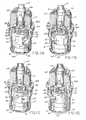
- Figs. 11A-11D illustrate that the valve cartridge can be used for both a right-hand or left-hand operation.
- Figs. 11A and 11B show its usage in right-hand operation (e.g. for a cold water line) wherein a clockwise motion is employed to open and a counterclockwise motion to close.
- Figs. 11C and 11D represent its operation in a left-hand manner (e.g. for a hot water line) wherein a counterclockwise motion is employed to open and a clockwise motion to close.
- Fig. 11A the valve cartridge is shown in a closed position with respect to fluid flow. It will be noted that the relief area 59 is positioned over a solid portion of the stationary element 31 with the inlets 54 and 55 blocked. Counter-clockwise rotation is prevented by bar 28 abutting against one side of stop wedges 58. To effect an opening of the valve, the stem 19 is rotated in a clockwise manner as indicated by the directional arrow in Fig. 11A. It should be noted in this connection that bar 28 has been placed in the slot 34 of the movable valve element 30 with the ends of the projection designated for reference purposes by 28a and 28b.
- a 90 o rotation is the most that can be effected for the stem and the projection 28 as the rotation is limited by the other side of opposing wedges 58. (See Fig. 7 for the positioning of stops 58).
- the 90 o rotation will move the relief area 59 over the opening 54 in the stationary valve member 31.
- relief area 60 is aligned with inlet 55. The valve is thus in the full open position. Note that during this particular movement, the valve was moved in a clockwise manner to effect the opening. To close the valve, a counterclockwise motion would be imparted as indicated by the direction arrow in Fig. 11B, thereby bringing the valve back to the position shown in Fig. 11A.
- Fig. 11C the projection 28 is now placed in the slot 35 rather than the slot 34.
- the valve is closed as indicated by the relief portion 59 being out of orientation with either of the openings 54 or 55.
- a counterclockwise motion must be imparted to the valve stem 19 as indicated by the direction arrow in Fig. 11C.
- the relief area 59 will also be moved in a counterclockwise motion to be orientated over the opening 55 while the relief area 60 is brought into communication with the opening 54.
- the end portion 28b of the projection 28 will be moved to a position indicated in broken lines in Fig. 11D and the end portion 28a will be moved to that shown also in Fig. 11D.
- a counterclockwise motion opens the valve with a clockwise motion closes it as indicated by the directional arrow in Fig. 11D.
- the stem 19 can be easily and securely mounted in the valve body 17 without having to machine a groove in the valve stem and use the usual C-type clip. All that is required in this instance is to move the valve stem 19 upwardly into the valve body 17 as suggested in Fig. 10. This upward motion is contined until the flange 29 contacts the internal shoulder 24 (see Fig. 2). The washer 25 is then placed down over the shank portion of the valve stem 19 with the push nut 26 being forced over the outer surface thereof. As indicated earlier, the push nut 26 is designed so that it can be pushed downwardly to the desired extent but cannot be moved in the upward direction. This feature not only avoids having to machine a groove for attachment purposes but also aboids having to compensate for tolerances between the groove and the flange 29 contacting the valve body for purposes of effecting a tight engagement.
- valve assembly resides in the manner of the water passage through the movable valve element. This is effected by the curved wall surface 38 in the movable valve element 30. Tapered inlets in holes 54 and 55 as well as curved surface 71 further smooth out the flow and reduce noise.
- the invention provides an improved valve. While the preferred embodiment has been described above, it is readily apparent to those skilled in the art that a number of modifications and changes may be made without departing from the spirit and scope of the invention. For example, while a faucet has been shown, the valve can be used with other types of fluid valves. Also, the specific materials mention are not the only materials which can be used. All such and other modifications within the spirit of the invention are meant to be in the scope of the invention.
Landscapes
- Engineering & Computer Science (AREA)
- General Engineering & Computer Science (AREA)
- Mechanical Engineering (AREA)
- Sliding Valves (AREA)
- Multiple-Way Valves (AREA)
- Lift Valve (AREA)
- Mechanically-Actuated Valves (AREA)
- Taps Or Cocks (AREA)
Applications Claiming Priority (2)
| Application Number | Priority Date | Filing Date | Title |
|---|---|---|---|
| US205284 | 1988-06-10 | ||
| US07/205,284 US4821765A (en) | 1988-06-10 | 1988-06-10 | Valve for faucet or the like |
Publications (2)
| Publication Number | Publication Date |
|---|---|
| EP0345604A2 true EP0345604A2 (de) | 1989-12-13 |
| EP0345604A3 EP0345604A3 (de) | 1990-05-30 |
Family
ID=22761579
Family Applications (1)
| Application Number | Title | Priority Date | Filing Date |
|---|---|---|---|
| EP89109730A Withdrawn EP0345604A3 (de) | 1988-06-10 | 1989-05-30 | Sanitäres Ventil |
Country Status (9)
| Country | Link |
|---|---|
| US (1) | US4821765A (de) |
| EP (1) | EP0345604A3 (de) |
| JP (1) | JPH0627554B2 (de) |
| KR (1) | KR900000624A (de) |
| AU (1) | AU628058B2 (de) |
| CA (1) | CA1318650C (de) |
| DE (1) | DE345604T1 (de) |
| ES (1) | ES2013583A4 (de) |
| MX (1) | MX168189B (de) |
Cited By (2)
| Publication number | Priority date | Publication date | Assignee | Title |
|---|---|---|---|---|
| CN102588628A (zh) * | 2011-12-26 | 2012-07-18 | 广州海鸥卫浴用品股份有限公司 | 一种阀芯组件及采用该阀芯组件的阀门 |
| CN101660629B (zh) * | 2008-08-28 | 2012-08-08 | 昆山康勤精密阀芯有限公司 | 控水阀芯的侧向出水导流筒套结构 |
Families Citing this family (59)
| Publication number | Priority date | Publication date | Assignee | Title |
|---|---|---|---|---|
| GB2228985B (en) * | 1989-04-04 | 1993-07-21 | Galatron Srl | 'breech-block' tap for the supply of cold or hot water with ceramic sealing plates |
| US5012833A (en) * | 1989-09-29 | 1991-05-07 | Amtrol Inc. | Freeze-proof hydrant |
| US4971097A (en) * | 1989-09-29 | 1990-11-20 | Amtrol Inc. | Freeze-proof hydrant |
| IT222220Z2 (it) * | 1989-11-08 | 1995-02-01 | Galatron Srl | Coppia di piastrine per controllare l'erogazione di fluido in valvole tipo vitone |
| IT1236011B (it) * | 1989-11-08 | 1992-12-15 | Galatron Srl | Valvola tipo vitone con tenuta a piastrine ceramiche |
| US4973025A (en) * | 1989-12-26 | 1990-11-27 | Kohler Co. | Metering valve |
| US5010917A (en) * | 1990-04-02 | 1991-04-30 | Kohler Co. | Fluid control valve |
| US5042529A (en) * | 1990-12-21 | 1991-08-27 | Wan Tiao Yeh | Structure of water flow regulating device |
| US5174324A (en) * | 1991-01-22 | 1992-12-29 | Amerikam | Ceramic valve |
| USRE35545E (en) * | 1991-01-22 | 1997-07-01 | Amerikam, Inc. | Ceramic valve |
| DE4101836A1 (de) * | 1991-01-23 | 1992-07-30 | Traenkle Anton Kg | Ventiloberteil |
| AU640020B2 (en) * | 1991-05-22 | 1993-08-12 | Wan Tiao Yeh | Structure of water flow regulating device |
| CH685205A5 (de) * | 1992-05-18 | 1995-04-28 | Fides Treuhand Gmbh | Anschlussvorrichtung für eine sanitäre Mischarmatur. |
| US5392805A (en) * | 1993-07-27 | 1995-02-28 | Amerikam, Inc. | Frost-resistant hydrant |
| US5669407A (en) * | 1994-03-24 | 1997-09-23 | Masco Corporation Of Indiana | Compression cartridge for a faucet valve assembly |
| US5398717A (en) * | 1994-04-15 | 1995-03-21 | Kohler Co. | Fluid valve |
| US5531524A (en) * | 1994-09-02 | 1996-07-02 | Kohler Co. | Self-adjusting bearing |
| US5681028A (en) * | 1995-10-23 | 1997-10-28 | Emhart Inc. | Valve assembly |
| US5732734A (en) * | 1995-10-19 | 1998-03-31 | Sterling Plumbing Group, Inc. | Plumbing valve |
| US5692536A (en) * | 1995-11-13 | 1997-12-02 | Masco Corporation Of Indiana | Invertible quarter turn stop |
| US5826788A (en) * | 1996-01-25 | 1998-10-27 | Kohler Co. | Handle assembly for rotatable stem |
| US5904336A (en) * | 1996-04-15 | 1999-05-18 | Emhart Inc. | Valve assembly |
| US5918626A (en) * | 1996-12-30 | 1999-07-06 | Delta Engineering Holdings Limited | Self regulating quarter turn faucet valve with no metal components |
| USD402354S (en) | 1997-10-09 | 1998-12-08 | Delta Engineering Holdings Limited | Flange mask |
| US6293299B1 (en) | 1999-08-05 | 2001-09-25 | Masco Corporation Of Indiana | Temperature and flow limiting device |
| US6286808B1 (en) | 2000-02-25 | 2001-09-11 | Kohler Co. | Gravity flow faucet |
| DE20022320U1 (de) * | 2000-03-08 | 2001-07-26 | ANTON TRÄNKLE GMBH & CO KG, 78098 Triberg | Dichtungseinrichtung für ein Ventiloberteil, insbesondere für Wasserarmaturen |
| US6425571B1 (en) * | 2000-08-09 | 2002-07-30 | Parker-Hannifin Corporation | Valve and method for forming valve |
| US6382229B1 (en) | 2000-12-08 | 2002-05-07 | Emhart Llc | Valve assembly and seal therefor |
| US6732756B2 (en) * | 2001-07-16 | 2004-05-11 | Carl R. Brod | Adapter for valve and manifold assembly |
| KR20040040807A (ko) * | 2002-11-08 | 2004-05-13 | 박숙진 | 스톱밸브용 세라믹 디스크형 개폐카트리지 |
| US6802335B2 (en) * | 2003-01-23 | 2004-10-12 | Masco Corporation Of Indiana | Faucet handle retainer |
| KR100455360B1 (ko) * | 2004-05-07 | 2004-11-09 | 주식회사 한성시스코 | 냉난방배관용 전동밸브 |
| US7134450B2 (en) * | 2005-03-07 | 2006-11-14 | Chung Cheng Faucet Co., Ltd. | Interior structure of water control valve for faucets |
| US7331359B2 (en) * | 2005-04-19 | 2008-02-19 | Kohler Co. | Valve with bi-loading seal |
| CN101646889B (zh) * | 2007-01-31 | 2012-01-11 | 莫恩股份有限公司 | 对安装载荷不敏感的阀芯 |
| US8978700B2 (en) * | 2007-01-31 | 2015-03-17 | Moen Incorporated | Valve cartridge with improved flow rate |
| US20080179559A1 (en) * | 2007-01-31 | 2008-07-31 | Moen Incorporated | Valve cartridge with snap retainer tolerance absorber |
| CN100580295C (zh) * | 2007-02-09 | 2010-01-13 | 陈启岳 | 改进结构的温控水龙头 |
| US8956412B2 (en) * | 2007-06-22 | 2015-02-17 | Axiomed, LLC | Artificial disc |
| CN201507719U (zh) * | 2009-09-17 | 2010-06-16 | 路达(厦门)工业有限公司 | 龙头分体式阀座 |
| US8739818B1 (en) * | 2010-08-02 | 2014-06-03 | Living Trust of John B. Woods and Nola Fae Woods | Control valve with single set of orifices |
| US9303391B2 (en) | 2010-09-16 | 2016-04-05 | Kohler Co. | Faucet mount assembly |
| US10260642B2 (en) * | 2011-04-26 | 2019-04-16 | As Ip Holdco, Llc | Faucet valve cartridge |
| US20120305117A1 (en) * | 2011-06-06 | 2012-12-06 | Tsung-Min Huang | Lead-free valve of faucet and process of manufacturing same |
| US10344461B2 (en) * | 2016-04-17 | 2019-07-09 | Jorge Maercovich | Valve actuation control for flush urinal and toilet apparatus |
| WO2017210568A1 (en) * | 2016-06-02 | 2017-12-07 | Component Hardware Group, Inc. | Valve for a faucet assembly |
| CN106051223B (zh) * | 2016-07-27 | 2018-09-07 | 路达(厦门)工业有限公司 | 混合阀及龙头装置 |
| US10113661B2 (en) | 2016-08-30 | 2018-10-30 | Griswold Controls, Llc | Flow control valve |
| US10753075B2 (en) | 2016-09-26 | 2020-08-25 | Zurn Industries, Llc | Flush valve |
| US10578228B2 (en) | 2016-09-26 | 2020-03-03 | Zurn Industries, Llc | Sensing mechanism for valve operation |
| US10487486B2 (en) | 2017-02-08 | 2019-11-26 | Zurn Industries, Llc | Flush valve with relief valve having axially-translatable valve element |
| US10385978B2 (en) | 2017-10-21 | 2019-08-20 | Hector Hernandez | Cartridge assembly for regulating flows |
| US10900474B2 (en) | 2018-06-28 | 2021-01-26 | Eugene R. Prais | System and method for hand pump faucet |
| ES2863987T3 (es) * | 2018-07-02 | 2021-10-13 | Fluehs Drehtechnik Gmbh | Parte superior de válvula |
| US11897753B2 (en) * | 2018-07-26 | 2024-02-13 | Kagura Feast Corp. | Dispenser and cock |
| USD883444S1 (en) | 2018-12-04 | 2020-05-05 | Zurn Industries, Llc | Flush valve housing |
| US11384851B2 (en) | 2019-10-08 | 2022-07-12 | Hector Hernandez | Cartridge assembly for diverting flow |
| HUE065547T2 (hu) * | 2021-08-18 | 2024-06-28 | Fluehs Drehtechnik Gmbh | Szelep kartus |
Family Cites Families (24)
| Publication number | Priority date | Publication date | Assignee | Title |
|---|---|---|---|---|
| US880127A (en) * | 1906-10-08 | 1908-02-25 | Herbert H Cramer | Turning-plug. |
| US2321157A (en) * | 1942-03-13 | 1943-06-08 | Illinois Tool Works | Fastener device |
| US3389717A (en) * | 1966-07-15 | 1968-06-25 | Kohler Co | Removable valve unit with flow control device |
| US3425660A (en) * | 1966-08-17 | 1969-02-04 | Wallace Murray Corp | Faucet valve |
| US3570810A (en) * | 1969-01-31 | 1971-03-16 | Wallace Murray Corp | Faucet valve |
| CA957241A (en) * | 1971-04-09 | 1974-11-05 | Masco Corporation | Mixing valve |
| US3810602A (en) * | 1972-04-17 | 1974-05-14 | American Standard Inc | Ceramic disk faucet |
| US3780758A (en) * | 1972-11-15 | 1973-12-25 | Wolverine Brass Works Ind Inc | Non-metallic cartridge valve |
| US3807455A (en) * | 1973-03-19 | 1974-04-30 | Elkay Mfg Co | Replaceable cartridge for faucets |
| US3831621A (en) * | 1973-11-19 | 1974-08-27 | Union Brass & Metal Mfg | Rotary slide valve |
| US4005728A (en) * | 1975-08-29 | 1977-02-01 | Globe Valve Corporation | Faucet valve |
| DE2960712D1 (en) * | 1978-01-26 | 1981-11-26 | Ideal Standard Sa | Rotary valve |
| US4314581A (en) * | 1979-10-19 | 1982-02-09 | Streamway Corporation | Rotary valve washerless cartridge |
| US4331176A (en) * | 1980-03-03 | 1982-05-25 | American Standard Inc. | Replaceable cartridge valve assembly |
| IT8022457V0 (it) * | 1980-08-01 | 1980-08-01 | Zucchetti Rubinetteria Spa | Dispositivo di controllo del flusso d'acqua, per rubinetti. |
| DE3107431A1 (de) * | 1981-02-27 | 1982-09-16 | Friedrich Grohe Armaturenfabrik Gmbh & Co, 5870 Hemer | Absperr- und regulierventil |
| DE3207895C2 (de) * | 1982-03-05 | 1983-12-29 | Fa. Otto Flühs, 5880 Lüdenscheid | Ventiloberteil für Sanitärarmaturen |
| DE3309546A1 (de) * | 1983-03-17 | 1984-09-20 | Ideal-Standard Gmbh, 5300 Bonn | Durchgangsventil |
| JPS6150191A (ja) * | 1984-08-20 | 1986-03-12 | 株式会社光電製作所 | 直線化画像表示装置 |
| US4575881A (en) * | 1984-12-28 | 1986-03-18 | Kohler Co. | Perpendicular toilet trip lever assembly |
| GB8508734D0 (en) * | 1985-04-03 | 1985-05-09 | Morgan Matroc Ltd | Replacement headworks for draw-off taps |
| US4651770A (en) * | 1986-03-28 | 1987-03-24 | Speakman Company | Ceramic disc faucet valve |
| JPS61241580A (ja) * | 1986-04-24 | 1986-10-27 | Toto Ltd | 2バルブ式湯水混合栓 |
| US4700736A (en) * | 1987-01-05 | 1987-10-20 | Sheen Guang Yue | Faucet valve |
-
1988
- 1988-06-10 US US07/205,284 patent/US4821765A/en not_active Expired - Lifetime
-
1989
- 1989-05-30 ES ES89109730T patent/ES2013583A4/es active Pending
- 1989-05-30 DE DE198989109730T patent/DE345604T1/de active Pending
- 1989-05-30 EP EP89109730A patent/EP0345604A3/de not_active Withdrawn
- 1989-06-09 MX MX016385A patent/MX168189B/es unknown
- 1989-06-09 CA CA000602336A patent/CA1318650C/en not_active Expired - Fee Related
- 1989-06-09 AU AU36257/89A patent/AU628058B2/en not_active Ceased
- 1989-06-09 KR KR1019890007919A patent/KR900000624A/ko not_active Ceased
- 1989-06-09 JP JP1148175A patent/JPH0627554B2/ja not_active Expired - Lifetime
Cited By (2)
| Publication number | Priority date | Publication date | Assignee | Title |
|---|---|---|---|---|
| CN101660629B (zh) * | 2008-08-28 | 2012-08-08 | 昆山康勤精密阀芯有限公司 | 控水阀芯的侧向出水导流筒套结构 |
| CN102588628A (zh) * | 2011-12-26 | 2012-07-18 | 广州海鸥卫浴用品股份有限公司 | 一种阀芯组件及采用该阀芯组件的阀门 |
Also Published As
| Publication number | Publication date |
|---|---|
| KR900000624A (ko) | 1990-01-30 |
| AU628058B2 (en) | 1992-09-10 |
| AU3625789A (en) | 1989-12-14 |
| JPH0238769A (ja) | 1990-02-08 |
| MX168189B (es) | 1993-05-10 |
| EP0345604A3 (de) | 1990-05-30 |
| CA1318650C (en) | 1993-06-01 |
| JPH0627554B2 (ja) | 1994-04-13 |
| ES2013583A4 (es) | 1990-05-16 |
| DE345604T1 (de) | 1990-08-16 |
| US4821765A (en) | 1989-04-18 |
Similar Documents
| Publication | Publication Date | Title |
|---|---|---|
| EP0345604A2 (de) | Sanitäres Ventil | |
| CA1285258C (en) | Valve assembly | |
| CA2187869C (en) | Fluid cartridge valve | |
| US5010917A (en) | Fluid control valve | |
| US5273255A (en) | Quarter turn tap | |
| US4738277A (en) | Improvement in rotatable taps | |
| EP0432104B1 (de) | Steuereinheit für Warm- und Kaltwassermischventil | |
| US5107884A (en) | Pair of cooperating disks to control the delivery of liquid in so-called screw type valves | |
| US5417242A (en) | Fluid valve | |
| EP0424782A1 (de) | Selbstschliessende Ventilvorrichtung | |
| EP0770804A2 (de) | Drehschieberanordnung | |
| US8459303B2 (en) | Valve cartridge insensitive to installation load | |
| US2200474A (en) | Valve actuating mechanism | |
| GB2031125A (en) | Valve | |
| US6189561B1 (en) | Valve cartridge for lift valve having the closing pressure on the sealing limited | |
| EP0077506A1 (de) | Durchflussregelventil | |
| RU2101594C1 (ru) | Водопроводный смеситель | |
| CN218118708U (zh) | 一种侧进水端出水的混水调温阀芯 | |
| RU2084735C1 (ru) | Сменная головка вентиля | |
| JPH0712787Y2 (ja) | シングルレバー式水栓 | |
| CA1094040A (en) | Faucet valve with dual flow control | |
| JPH0366543B2 (de) | ||
| JPH07332512A (ja) | シングルレバー式水栓 | |
| HK1137500A (en) | Valve cartridge insensitive to installation load | |
| JPH0842723A (ja) | シングルレバー式水栓の可動ディスク弁体の取付構造 |
Legal Events
| Date | Code | Title | Description |
|---|---|---|---|
| PUAI | Public reference made under article 153(3) epc to a published international application that has entered the european phase |
Free format text: ORIGINAL CODE: 0009012 |
|
| AK | Designated contracting states |
Kind code of ref document: A2 Designated state(s): BE DE ES FR GB IT NL |
|
| ITCL | It: translation for ep claims filed |
Representative=s name: SOCIETA' ITALIANA BREVETTI S.P.A. |
|
| PUAL | Search report despatched |
Free format text: ORIGINAL CODE: 0009013 |
|
| TCNL | Nl: translation of patent claims filed | ||
| EL | Fr: translation of claims filed | ||
| AK | Designated contracting states |
Kind code of ref document: A3 Designated state(s): BE DE ES FR GB IT NL |
|
| DET | De: translation of patent claims | ||
| 17P | Request for examination filed |
Effective date: 19900911 |
|
| 17Q | First examination report despatched |
Effective date: 19920601 |
|
| STAA | Information on the status of an ep patent application or granted ep patent |
Free format text: STATUS: THE APPLICATION IS DEEMED TO BE WITHDRAWN |
|
| 18D | Application deemed to be withdrawn |
Effective date: 19931211 |