EP0345868B1 - Dispositif pour distribuer des pièces de monnaie - Google Patents
Dispositif pour distribuer des pièces de monnaie Download PDFInfo
- Publication number
- EP0345868B1 EP0345868B1 EP89201380A EP89201380A EP0345868B1 EP 0345868 B1 EP0345868 B1 EP 0345868B1 EP 89201380 A EP89201380 A EP 89201380A EP 89201380 A EP89201380 A EP 89201380A EP 0345868 B1 EP0345868 B1 EP 0345868B1
- Authority
- EP
- European Patent Office
- Prior art keywords
- rotary disc
- coin
- hopper
- carrier
- central circular
- Prior art date
- Legal status (The legal status is an assumption and is not a legal conclusion. Google has not performed a legal analysis and makes no representation as to the accuracy of the status listed.)
- Expired - Lifetime
Links
Images




Classifications
-
- G—PHYSICS
- G07—CHECKING-DEVICES
- G07D—HANDLING OF COINS OR VALUABLE PAPERS, e.g. TESTING, SORTING BY DENOMINATIONS, COUNTING, DISPENSING, CHANGING OR DEPOSITING
- G07D9/00—Counting coins; Handling of coins not provided for in the other groups of this subclass
- G07D9/008—Feeding coins from bulk
Definitions
- the present invention relates to a coin dispensing apparatus for use in coin exchangers, coin operated gaming machines or the like and more particularly to such a coin dispensing apparatus comprising a hopper for holding a supply of coins or tokens in bulk and a rotary disc for dispensing coins one at a time and in predetermined quantities.
- such a coin dispensing apparatus is known as disclosed in Japanese Patent Application Publication No. 62-45,588 (U.S. Patent Specification No. 4,589,433).
- a known coin dispensing apparatus comprises a hopper for holding a supply of coins in bulk and a rotary disc 3 rotatably disposed at one side within the hopper 1 at an angle to the horizontal.
- the rotary disc 3 has a central circular stage 4 provided at the central portion thereof and a plurality of coin transporting pins 5 arranged in a peripheral portion 3a around the central circular stage 4 such as to receive one coin between two sequential transporting pins 5 spaced apart in the peripheral direction of the rotary disc 3.
- the coin dispensing apparatus further comprises a delivery guide 7 and an outlet chute 6 which are fixed to a stationary frame at an upper delivery portion 3b.
- the delivery guide 7 extends from the outlet chute 13 to an upper periphery 4a of the central stage across the peripheral portion 3a of the rotary disc 3 in the upper delivery portion 3b and has a tunnel passage for passing the transporting pin 5.
- Aforementioned coin dispensing apparatus of prior art has a disadvantage in that the size of the coin transporting pin is limited since a large transporting pin can carry two or more coins at a time so that a coin counting device usually provided at the front of the outlet chute would make a miscount or the inlet of the outlet chute would be jammed with coins and further the dimension of the tunnel passage in the delivery guide must be increased.
- a coin counting device usually provided at the front of the outlet chute would make a miscount or the inlet of the outlet chute would be jammed with coins and further the dimension of the tunnel passage in the delivery guide must be increased.
- the object of the present invention is to improve the function of picking up coins from the bottom portion in a hopper by use of a long transporting pin without miscounting and jamming coins in the upper delivery portion.
- Another object of the present invention is to improve the coin dispensing efficiency by providing unique means for agitating coins in the lower portion of a hopper without miscounting and jamming coins in the upper delivery portion and increasing load for agitating coins.
- a coin dispensing apparatus comprising a hopper for holding a supply of coins or tokens in bulk, a rotary disc rotatably disposed within the hopper and provided with a central circular stage, a plurality of coin transporting pins which are protruded in a peripheral portion around the central circular stage and spaced apart in the peripheral direction of the rotary disc, and a coin delivery guide extended across the peripheral portion of the rotary disc for guiding coins on the peripheral portion to an outlet chute
- a carrier having a plurality of coin transporting pins spaced apart in the circumferential direction is rotatably supported at the rear side of the rotary disc to rotate at an angle to the rotary disc such as to extrude the pins extended through the rotary disc from the surface of the peripheral portion of the rotary disc in a minimum amount at a position of the delivery guide and in a maximum amount at a coin picking up position.
- a coin dispensing apparatus comprising a hopper for holding a supply of coins in bulk, a rotary disc rotatably disposed within the hopper and provided with a central circular stage, a plurality of coin transporting pins which are protruded in a peripheral portion around the central circular stage and spaced apart in the peripheral direction of the rotary disc, and a coin delivery guide extended across the peripheral portion of the rotary disc for guiding coins on the peripheral delivery portion to an outlet chute
- a carrier having a plurality of coin agitating members spaced apart in the circumferential direction is rotatably supported at the rear side of the rotary disc to rotate at an angle to the rotary disc such as to extrude coin agitating members extended through the rotary disc from the surface of the central circular stage of the rotary disc in a minimum amount at a position of the delivery portion and in a maximum amount at a coin picking up position.
- the rotary disc is rotatably disposed at one side within the hopper at an angle to the horizontal.
- the carrier has a plurality of coin transporting pins spaced apart in the circumferential direction and extended through the peripheral portion of the rotary disc and a plurality of coin agitating members spaced apart in the circumferential direction and extended through the central circular stage of the rotary disc.
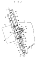
- a hopper 1 is connected to a stationary supporting plate 10 which is fixedly mounted on a conventional supporting stand in a position inclined to the horizontal in a known manner.
- the supporting plate 10 is provided with a rotary disc supporting surface 11 for supporting a rotary disc 3 with a central circular stage 4 and a carrier supporting surface 12 inclined relative to the rotary disc supporting surface 11 for supporting a disc shaped carrier 8.
- a rotating shaft 2 is driven by means of a motor 13 and is extended through a central hole 14 in the supporting plate 10.
- a plurality of rotary disc supporting balls 16 are spaced from each other in the circumferential direction and rotatably retained by means of a retainer ring 15 and then positioned in a circular race 17 formed in the supporting surface 11 on the supporting plate 10.
- a plurality of carrier supporting balls 21 are also spaced from each other in the circumferential direction and rotatably retained by means of a retainer ring 20 and then positioned in a circular race 22 formed in the supporting surface 12 on the supporting plate 10.
- the rotary disc 3 and the carrier 8 are rotatably supported on the rotating shaft 2 at their central holes, respectively.
- the carrier 8 is provided with a plurality of coin transporting pins 5 which are protruded from the surface toward the rotary disc 3 and spaced apart in the circumferential direction.
- the coin transporting pins 5 are respectively inserted in holes 9 which are formed in a peripheral portion 3a of the rotary disc 3 and spaced apart in the circumferential direction by the same space as that between the coin transporting pins.
- a spring 26 is interposed between the rotary disc 3 and the carrier 8 and a spring 25 is interposed between the rotary disc 3 and a washer 27 which is fixed to the top of the rotating shaft 2 by means of a screw 28 to thereby urge the central portions of the rotary disc 3 and the carrier 8 towards the stationary supporting plate 10 by means of springs 26 and 25, respectively to rotatably support the rotary disc 3 and the carrier 8 on the supporting plate through the balls 16 and 21, respectively.
- the rotating shaft 2 is provided with a driving pin 30 which is laterally extended from the shaft, while the rotary disc 3 is provided with a driven pin 31 which is protruded from the under surface of the rotary disc such as to be drivingly engaged with the driving pin 30, whereby the rotary disc 3 is driven by the rotating shaft 2.
- a plurality of screws 32 are threaded in tapped holes in the central circular stage 4 and the rotary disc 3 and extended through bearings 34 at holes 33 formed in the carrier 8 to thereby drivingly connect the carrier 8 to the rotary disc 3.
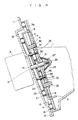
- the carrier 8 is integrally rotated with the rotary disc 3, but in an inclined position in respect to the rotary disc 3. Accordingly, the coin transporting pins 5 extend from the surface of the lower peripheral portion of the rotary disc 3 into the bottom portion of the hopper 1 in a maximum protrusion amount at a coin picking up position which is substantially diametrically opposed to the position of the delivery guide 7 at the upper delivery portion 3b and the protrusion amount of the coin transporting pins subsequently decreases to a protrusion amount corresponding to a thickness of one coin at the front of the outlet chute 6 as the rotary disc 3 is rotated and the coin transporting pins 5 approach to the outlet chute 6 at the upper delivery portion 3b.
- the coin transporting pin 5 When the coin transporting pin 5 reaches to the position of the delivery guide 7 at the upper delivery portion 3b, the coin transporting pin 5 is substantially withdrawn in the hole 9 as shown in Fig. 1.
- the coin transporting pin 5 is again extended from the surface of the peripheral portion 3a of the rotary disc 3 after passing the position of the delivery guide 7 and the extrusion amount of the pin 5 subsequently increases to the maximum amount.
- the present invention is able to effect a high picking up and agitating efficiency by the coin transporting pin 5, without any interference with the delivery guide 7 and the miscounting and jamming of coins at the upper delivery portion, so that the coin dispensing efficiency and the reliability in the operation of the coin dispensing apparatus are remarkably improved.
- the rotary disc 3 is arranged within the hopper 1 at an angle to the horizontal, but the rotary disc 3 may be arranged to rotate in a horizontal position.
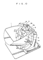
- Fig. 3 shows another embodiment, wherein the coin transporting pin 5 has a large dimension in the radial direction.
- Figs. 4 and 5 show a third embodiment of the present invention.
- a plurality of rod shaped agitating members 35 are secured to the inclined carrier 8 such as to extend through holes 36 and 37 formed in the rotary disc 3 and the central circular stage 4.
- Figs. 6 and 7 show other embodiment which is similar to the embodiment shown in Figs. 4 and 5, wherein the coin agitating members 35 are extended in the radial direction of the central circular stage 4.
- Figs. 8 and 9 show other embodiment of the present invention which is similar to the embodiment shown in Figs. 4 and 5 except of providing the coin transporting pins 5 integrally on the surface of the peripheral portion 3a of the rotary disc 3.
Landscapes
- Physics & Mathematics (AREA)
- General Physics & Mathematics (AREA)
- Feeding Of Articles To Conveyors (AREA)
- Filling Or Emptying Of Bunkers, Hoppers, And Tanks (AREA)
Claims (5)
- Appareil pour distribuer des pièces comprenant une trémie (1) pour contenir des pièces en vrac, une disque rotatif (3) disposé à tourner à l'intérieur de la trémie et prévu avec un palier circulaire central (4), une pluralité de broches de transport de pièce (5) qui dépassent dans une partie périphérique (3a) autour du palier circulaire central (4) et qui sont espacées dans la direction périphérique du disque rotatif (3), un guide pour délivrer les pièces (7) qui se prolonge à travers la partie périphérique du disque rotatif pour guider les pièces sur la partie de déchargement périphérique (3b) vers une goulotte de sortie (8) caractérisé par un support (8) comportant une pluralité de broches de transport de pièce (5) espacées dans la direction circonférentielle, ledit support (8) étant supporté à tourner sur l'extrémité arrière du disque rotatif pour tourner d'un certain angle par rapport au disque rotatif de manière à extruder les broches (5) qui sortent à travers le disque rotatif (3) à partir de la surface de la partie périphérique (3a) du disque rotatif (3) d'une faible valeur à l'emplacement du guide de déchargement (7) et d'une valeur plus importante à une position de prélèvement des pièces.
- Appareil selon la revendication 1, dans lequel le disque rotatif (3) est disposé à tourner sur un côté à l'intérieur de la trémie (1) à un certain angle par rapport à l'horizontale.
- Appareil selon la revendication 1, dans lequel le support (8) est prévu avec une pluralité d'éléments d'agitation (35) espacés dans la direction circonférentielle d'une manière telle à se prolonger à travers le palier circulaire central (4) du disque rotatif (3).
- Appareil pour distribuer des pièces comprenant une trémie (1) pour contenir des pièces en vrac, un disque rotatif (3) disposé à tourner à l'intérieur de la trémie et prévu avec un palier circulaire central (4), une pluralité de broches de transport de pièce (5) qui dépassent dans une partie périphérique (3a) autour du palier circulaire central (4) et qui sont espacées dans la direction périphérique du disque rotatif (3), un guide pour délivrer les pièces (7) qui se prolonge à travers la partie périphérique du disque rotatif pour guider les pièces sur la partie de déchargement périphérique (3b) vers une goulotte de sortie (8), caractérisé par un support (8) comportant une pluralité d'éléments d'agitation de pièce (35) espacés dans la direction circonférentielle, ledit support (8) étant supporté à tourner sur le côté arrière du disque rotatif pour tourner d'un certain angle par rapport au disque rotatif de façon à extruder les éléments d'agitation de pièce (35) qui se prolongent à travers le disque rotatif (3) à partir de la surface du palier circulaire central (4) du disque rotatif (3) d'une valeur minimale à un emplacement de la partie de déchargement et d'une valeur maximale à une position de prélèvement de pièces.
- Appareil selon la revendication 4, dans lequel le disque rotatif (3) est disposé à tourner sur un côté à l'intérieur de la trémie (1) à un certain angle par rapport à l'horizontale.
Priority Applications (1)
| Application Number | Priority Date | Filing Date | Title |
|---|---|---|---|
| AT89201380T ATE93076T1 (de) | 1988-06-04 | 1989-05-31 | Muenzausgabevorrichtung. |
Applications Claiming Priority (4)
| Application Number | Priority Date | Filing Date | Title |
|---|---|---|---|
| JP136665/88 | 1988-06-04 | ||
| JP63136665A JPH0797420B2 (ja) | 1988-06-04 | 1988-06-04 | 硬貨送出装置 |
| JP63327535A JP2578654B2 (ja) | 1988-12-27 | 1988-12-27 | 硬貨送出装置 |
| JP327535/88 | 1988-12-27 |
Publications (3)
| Publication Number | Publication Date |
|---|---|
| EP0345868A2 EP0345868A2 (fr) | 1989-12-13 |
| EP0345868A3 EP0345868A3 (fr) | 1991-01-09 |
| EP0345868B1 true EP0345868B1 (fr) | 1993-08-11 |
Family
ID=26470173
Family Applications (1)
| Application Number | Title | Priority Date | Filing Date |
|---|---|---|---|
| EP89201380A Expired - Lifetime EP0345868B1 (fr) | 1988-06-04 | 1989-05-31 | Dispositif pour distribuer des pièces de monnaie |
Country Status (4)
| Country | Link |
|---|---|
| US (1) | US5000718A (fr) |
| EP (1) | EP0345868B1 (fr) |
| DE (1) | DE68908284T2 (fr) |
| ES (1) | ES2042973T3 (fr) |
Cited By (1)
| Publication number | Priority date | Publication date | Assignee | Title |
|---|---|---|---|---|
| US12567298B2 (en) | 2019-06-28 | 2026-03-03 | Scan Coin Ab | Coin feeding unit, a module comprising said coin feeding unit, and a coin handling machine |
Families Citing this family (17)
| Publication number | Priority date | Publication date | Assignee | Title |
|---|---|---|---|---|
| JPH03104271U (fr) * | 1990-02-13 | 1991-10-29 | ||
| JP2946468B2 (ja) * | 1990-03-13 | 1999-09-06 | 旭精工株式会社 | コイン送出装置 |
| JPH03262092A (ja) * | 1990-03-13 | 1991-11-21 | Asahi Seiko Kk | 循環式コイン供給回収洗浄装置 |
| JPH0644305B2 (ja) * | 1990-06-13 | 1994-06-08 | 旭精工株式会社 | コイン送出装置 |
| JPH0624930Y2 (ja) * | 1990-10-16 | 1994-06-29 | 旭精工株式会社 | コイン送出装置 |
| JPH0528340A (ja) * | 1991-07-19 | 1993-02-05 | Asahi Seiko Kk | コイン送出装置 |
| US5326312A (en) * | 1991-09-13 | 1994-07-05 | Boardwalk Regency Corp. | Coin/token dispensing unit |
| JPH05159126A (ja) * | 1991-12-02 | 1993-06-25 | Asahi Seiko Kk | 硬貨送出装置 |
| US5232399A (en) * | 1992-03-11 | 1993-08-03 | Atoll Technology | Devices for the separation of coins, token and the like |
| JP2573634Y2 (ja) * | 1993-02-05 | 1998-06-04 | 旭精工株式会社 | 硬貨送出装置 |
| ES2119709B1 (es) * | 1996-11-26 | 1999-07-01 | Azkoyen Ind Sa | Devolvedor de monedas para mecanismos de pago. |
| ES2144964B1 (es) * | 1998-07-31 | 2001-02-01 | Azkoyen Medios De Pago Sa | Devolvedor de monedas para maquinas accionadas por monedas. |
| US6739965B2 (en) | 2002-05-14 | 2004-05-25 | Floyd K. String | High speed, high volume coin sorter |
| EP2081160B1 (fr) * | 2004-12-28 | 2013-06-19 | Glory Ltd. | Machine de distribution et de dépôt de monnaie |
| US20060154589A1 (en) * | 2005-01-11 | 2006-07-13 | String Gregory F | High speed coin processing machine |
| TW200905612A (en) * | 2007-05-28 | 2009-02-01 | Asahi Seiko Co Ltd | Coin hopper |
| US8371911B2 (en) | 2008-01-28 | 2013-02-12 | Glory Ltd. | Coin transporting device and coin handling machine |
Family Cites Families (7)
| Publication number | Priority date | Publication date | Assignee | Title |
|---|---|---|---|---|
| SE359669B (fr) * | 1971-05-28 | 1973-09-03 | Scan Coin Ab | |
| US3788334A (en) * | 1971-08-05 | 1974-01-29 | Ncr | Rotary disk coin dispenser with spring tabs |
| US3942544A (en) * | 1973-08-01 | 1976-03-09 | Spiral Step Tool Company | Hopper payout for various coin denominations |
| JPS5572290A (en) * | 1978-11-22 | 1980-05-30 | Omron Tateisi Electronics Co | Coin sending unit |
| ES261942U (es) * | 1981-11-18 | 1982-05-16 | Alvarez Gonzalez Pedro | Pagador rotativo para maquinas recreativas . |
| US4589433A (en) * | 1983-12-07 | 1986-05-20 | Asahi Seiko Kabushiki Kaisha | Coin dispensing apparatus |
| GB8625531D0 (en) * | 1986-10-24 | 1986-11-26 | Coin Controls | Coin dispensing apparatus |
-
1989
- 1989-05-30 US US07/358,836 patent/US5000718A/en not_active Expired - Lifetime
- 1989-05-31 ES ES89201380T patent/ES2042973T3/es not_active Expired - Lifetime
- 1989-05-31 DE DE89201380T patent/DE68908284T2/de not_active Expired - Fee Related
- 1989-05-31 EP EP89201380A patent/EP0345868B1/fr not_active Expired - Lifetime
Cited By (1)
| Publication number | Priority date | Publication date | Assignee | Title |
|---|---|---|---|---|
| US12567298B2 (en) | 2019-06-28 | 2026-03-03 | Scan Coin Ab | Coin feeding unit, a module comprising said coin feeding unit, and a coin handling machine |
Also Published As
| Publication number | Publication date |
|---|---|
| US5000718A (en) | 1991-03-19 |
| EP0345868A2 (fr) | 1989-12-13 |
| ES2042973T3 (es) | 1993-12-16 |
| DE68908284T2 (de) | 1994-02-10 |
| DE68908284D1 (en) | 1993-09-16 |
| EP0345868A3 (fr) | 1991-01-09 |
Similar Documents
| Publication | Publication Date | Title |
|---|---|---|
| US5000718A (en) | Coin dispensing apparatus | |
| EP0461889B1 (fr) | Distributeur de pièces de monnaie | |
| US4589433A (en) | Coin dispensing apparatus | |
| US5098340A (en) | Coin feeder | |
| US4810230A (en) | Coin dispenser | |
| US4036242A (en) | Hopper payout for various coin denominations | |
| US7681708B2 (en) | Apparatus for sorting articles | |
| AU647504B2 (en) | High capacity coin hopper for a gaming machine | |
| EP0526049B1 (fr) | Dispositif d'alimentation de pièces de monnaie | |
| WO1999033030A1 (fr) | Appareil a compter la monnaie et machine de depot de monnaie comprenant cet appareil | |
| US3815730A (en) | Orienting apparatus and method | |
| US6350193B1 (en) | Coin hopper coin feeder mechanism | |
| EP0594902A1 (fr) | Trieur de pièces de monnaie avec un convoyeur vertical | |
| US3612073A (en) | Coin payout mechanism for amusement device | |
| EP0442696B1 (fr) | Appareil de distribution de pièces | |
| US5066262A (en) | Coin dispensing apparatus | |
| JPH0624930Y2 (ja) | コイン送出装置 | |
| JP2504840Y2 (ja) | 硬貨処理機の硬貨搬送装置 | |
| JP3129396B2 (ja) | 直径変更可能な円板体送出装置 | |
| KR930003894Y1 (ko) | 주화 송출 장치 | |
| JPH01306980A (ja) | 硬貨送出装置 | |
| EP0146294B1 (fr) | Appareil distributeur de pièces de monnaie | |
| JPH02173891A (ja) | 硬貨送出装置 | |
| JPH0330931Y2 (fr) | ||
| JPS5880789A (ja) | 自動販売機 |
Legal Events
| Date | Code | Title | Description |
|---|---|---|---|
| PUAI | Public reference made under article 153(3) epc to a published international application that has entered the european phase |
Free format text: ORIGINAL CODE: 0009012 |
|
| AK | Designated contracting states |
Kind code of ref document: A2 Designated state(s): AT DE ES FR GB NL SE |
|
| PUAL | Search report despatched |
Free format text: ORIGINAL CODE: 0009013 |
|
| AK | Designated contracting states |
Kind code of ref document: A3 Designated state(s): AT DE ES FR GB NL SE |
|
| 17P | Request for examination filed |
Effective date: 19901227 |
|
| 17Q | First examination report despatched |
Effective date: 19921218 |
|
| GRAA | (expected) grant |
Free format text: ORIGINAL CODE: 0009210 |
|
| AK | Designated contracting states |
Kind code of ref document: B1 Designated state(s): AT DE ES FR GB NL SE |
|
| REF | Corresponds to: |
Ref document number: 93076 Country of ref document: AT Date of ref document: 19930815 Kind code of ref document: T |
|
| REF | Corresponds to: |
Ref document number: 68908284 Country of ref document: DE Date of ref document: 19930916 |
|
| ET | Fr: translation filed | ||
| REG | Reference to a national code |
Ref country code: ES Ref legal event code: FG2A Ref document number: 2042973 Country of ref document: ES Kind code of ref document: T3 |
|
| PLBE | No opposition filed within time limit |
Free format text: ORIGINAL CODE: 0009261 |
|
| STAA | Information on the status of an ep patent application or granted ep patent |
Free format text: STATUS: NO OPPOSITION FILED WITHIN TIME LIMIT |
|
| 26N | No opposition filed | ||
| EAL | Se: european patent in force in sweden |
Ref document number: 89201380.6 |
|
| EUG | Se: european patent has lapsed | ||
| REG | Reference to a national code |
Ref country code: GB Ref legal event code: IF02 |
|
| PGFP | Annual fee paid to national office [announced via postgrant information from national office to epo] |
Ref country code: SE Payment date: 20060505 Year of fee payment: 18 |
|
| PGFP | Annual fee paid to national office [announced via postgrant information from national office to epo] |
Ref country code: AT Payment date: 20060511 Year of fee payment: 18 |
|
| PGFP | Annual fee paid to national office [announced via postgrant information from national office to epo] |
Ref country code: FR Payment date: 20060515 Year of fee payment: 18 |
|
| PGFP | Annual fee paid to national office [announced via postgrant information from national office to epo] |
Ref country code: NL Payment date: 20060517 Year of fee payment: 18 |
|
| PGFP | Annual fee paid to national office [announced via postgrant information from national office to epo] |
Ref country code: DE Payment date: 20060525 Year of fee payment: 18 |
|
| PGFP | Annual fee paid to national office [announced via postgrant information from national office to epo] |
Ref country code: ES Payment date: 20060526 Year of fee payment: 18 |
|
| PGFP | Annual fee paid to national office [announced via postgrant information from national office to epo] |
Ref country code: GB Payment date: 20060531 Year of fee payment: 18 |
|
| GBPC | Gb: european patent ceased through non-payment of renewal fee |
Effective date: 20070531 |
|
| PG25 | Lapsed in a contracting state [announced via postgrant information from national office to epo] |
Ref country code: NL Free format text: LAPSE BECAUSE OF NON-PAYMENT OF DUE FEES Effective date: 20071201 |
|
| NLV4 | Nl: lapsed or anulled due to non-payment of the annual fee |
Effective date: 20071201 |
|
| EUG | Se: european patent has lapsed | ||
| PG25 | Lapsed in a contracting state [announced via postgrant information from national office to epo] |
Ref country code: AT Free format text: LAPSE BECAUSE OF NON-PAYMENT OF DUE FEES Effective date: 20070531 |
|
| REG | Reference to a national code |
Ref country code: FR Ref legal event code: ST Effective date: 20080131 |
|
| PG25 | Lapsed in a contracting state [announced via postgrant information from national office to epo] |
Ref country code: DE Free format text: LAPSE BECAUSE OF NON-PAYMENT OF DUE FEES Effective date: 20071201 |
|
| PG25 | Lapsed in a contracting state [announced via postgrant information from national office to epo] |
Ref country code: GB Free format text: LAPSE BECAUSE OF NON-PAYMENT OF DUE FEES Effective date: 20070531 |
|
| PG25 | Lapsed in a contracting state [announced via postgrant information from national office to epo] |
Ref country code: SE Free format text: LAPSE BECAUSE OF NON-PAYMENT OF DUE FEES Effective date: 20070601 |
|
| PG25 | Lapsed in a contracting state [announced via postgrant information from national office to epo] |
Ref country code: FR Free format text: LAPSE BECAUSE OF NON-PAYMENT OF DUE FEES Effective date: 20070531 |
|
| REG | Reference to a national code |
Ref country code: ES Ref legal event code: FD2A Effective date: 20070601 |
|
| PG25 | Lapsed in a contracting state [announced via postgrant information from national office to epo] |
Ref country code: ES Free format text: LAPSE BECAUSE OF NON-PAYMENT OF DUE FEES Effective date: 20070601 |