EP0346780A2 - Tendeur de pantalons ou de jupes - Google Patents
Tendeur de pantalons ou de jupes Download PDFInfo
- Publication number
- EP0346780A2 EP0346780A2 EP89110511A EP89110511A EP0346780A2 EP 0346780 A2 EP0346780 A2 EP 0346780A2 EP 89110511 A EP89110511 A EP 89110511A EP 89110511 A EP89110511 A EP 89110511A EP 0346780 A2 EP0346780 A2 EP 0346780A2
- Authority
- EP
- European Patent Office
- Prior art keywords
- skirt
- profile
- tensioner according
- central part
- pants
- Prior art date
- Legal status (The legal status is an assumption and is not a legal conclusion. Google has not performed a legal analysis and makes no representation as to the accuracy of the status listed.)
- Granted
Links
- 239000000725 suspension Substances 0.000 claims abstract description 18
- 239000011435 rock Substances 0.000 claims description 20
- 230000009471 action Effects 0.000 claims description 8
- 230000003014 reinforcing effect Effects 0.000 claims description 5
- 230000002787 reinforcement Effects 0.000 claims description 4
- 230000008878 coupling Effects 0.000 claims description 3
- 238000010168 coupling process Methods 0.000 claims description 3
- 238000005859 coupling reaction Methods 0.000 claims description 3
- 238000002347 injection Methods 0.000 claims description 3
- 239000007924 injection Substances 0.000 claims description 3
- 230000001960 triggered effect Effects 0.000 claims 1
- 238000004519 manufacturing process Methods 0.000 abstract description 6
- 238000005516 engineering process Methods 0.000 abstract description 2
- 230000008901 benefit Effects 0.000 description 5
- 230000006835 compression Effects 0.000 description 5
- 238000007906 compression Methods 0.000 description 5
- 238000010276 construction Methods 0.000 description 3
- 230000002349 favourable effect Effects 0.000 description 2
- 238000003780 insertion Methods 0.000 description 2
- 230000037431 insertion Effects 0.000 description 2
- 239000000463 material Substances 0.000 description 2
- 230000007704 transition Effects 0.000 description 2
- 238000013459 approach Methods 0.000 description 1
- 230000001747 exhibiting effect Effects 0.000 description 1
- 230000001771 impaired effect Effects 0.000 description 1
- 230000006872 improvement Effects 0.000 description 1
- 238000001746 injection moulding Methods 0.000 description 1
- 230000007246 mechanism Effects 0.000 description 1
- 238000000465 moulding Methods 0.000 description 1
- 230000000149 penetrating effect Effects 0.000 description 1
- 230000009467 reduction Effects 0.000 description 1
- 230000007480 spreading Effects 0.000 description 1
Images



Classifications
-
- A—HUMAN NECESSITIES
- A47—FURNITURE; DOMESTIC ARTICLES OR APPLIANCES; COFFEE MILLS; SPICE MILLS; SUCTION CLEANERS IN GENERAL
- A47G—HOUSEHOLD OR TABLE EQUIPMENT
- A47G25/00—Household implements used in connection with wearing apparel; Dress, hat or umbrella holders
- A47G25/62—Trouser or skirt stretchers or tensioners of the hanger type
- A47G25/621—Trouser or skirt stretchers or tensioners of the hanger type for stretching or tensioning trouser leg ends or the trouser skirt waistband comprising gripping members being urged apart
- A47G25/622—Trouser or skirt stretchers or tensioners of the hanger type for stretching or tensioning trouser leg ends or the trouser skirt waistband comprising gripping members being urged apart at least one gripping member comprising an arm urged outwardly by a spring member
- A47G25/624—Trouser or skirt stretchers or tensioners of the hanger type for stretching or tensioning trouser leg ends or the trouser skirt waistband comprising gripping members being urged apart at least one gripping member comprising an arm urged outwardly by a spring member the arms being concurrently movable, e.g. by a rack and pinion mechanism
-
- A—HUMAN NECESSITIES
- A47—FURNITURE; DOMESTIC ARTICLES OR APPLIANCES; COFFEE MILLS; SPICE MILLS; SUCTION CLEANERS IN GENERAL
- A47G—HOUSEHOLD OR TABLE EQUIPMENT
- A47G25/00—Household implements used in connection with wearing apparel; Dress, hat or umbrella holders
- A47G25/14—Clothing hangers, e.g. suit hangers
- A47G25/44—Slidable hangers ; Adjustable hangers
- A47G25/441—Slidable hangers ; Adjustable hangers having adjustable width
- A47G25/445—Slidable hangers ; Adjustable hangers having adjustable width to support trousers or skirts at the waistband or leg ends
- A47G25/446—Slidable hangers ; Adjustable hangers having adjustable width to support trousers or skirts at the waistband or leg ends comprising gripping members being concurrently adjustable, e.g. by a rack and pinion mechanism
-
- A—HUMAN NECESSITIES
- A47—FURNITURE; DOMESTIC ARTICLES OR APPLIANCES; COFFEE MILLS; SPICE MILLS; SUCTION CLEANERS IN GENERAL
- A47G—HOUSEHOLD OR TABLE EQUIPMENT
- A47G25/00—Household implements used in connection with wearing apparel; Dress, hat or umbrella holders
- A47G25/62—Trouser or skirt stretchers or tensioners of the hanger type
- A47G25/621—Trouser or skirt stretchers or tensioners of the hanger type for stretching or tensioning trouser leg ends or the trouser skirt waistband comprising gripping members being urged apart
- A47G25/622—Trouser or skirt stretchers or tensioners of the hanger type for stretching or tensioning trouser leg ends or the trouser skirt waistband comprising gripping members being urged apart at least one gripping member comprising an arm urged outwardly by a spring member
- A47G25/623—Trouser or skirt stretchers or tensioners of the hanger type for stretching or tensioning trouser leg ends or the trouser skirt waistband comprising gripping members being urged apart at least one gripping member comprising an arm urged outwardly by a spring member the hanger being adjustable to garment width
Definitions
- the invention relates to a skirt or trousers tensioner with a central part having a suspension hook and a U-shaped cross section, and two tensioning arms that can be moved in this manner to different spans.
- Skirt or trousers tensioners of the aforementioned construction are made of plastic and mostly serve as one-way hangers. They have the advantage that they can be used for a relatively large span range and are easy to handle.
- the tensioner is inserted with one tension arm into the waistband and the other tension arm is adjusted until it can also be inserted into the waistband.
- the tension arms are either under spring force, which urges them outwards, so that when inserting them into the collar, one tension arm must be pressed inwards. If this tension arm is then released, it is pushed outwards under the action of the spring and in this way tightens the garment on the waistband.
- the tensioning arms are in the middle part via a coupling that allows an opposite movement connected and adjusted by hand to the desired span and then locked.
- the clamping arms can be manufactured relatively easily in a two-part injection molding tool
- the production of the central part requires a comparatively complex tool that has one or two tool parts that mold the outside, a core that molds the U-profile at least in its lower region, and at least two slides must form the channels or guides for the springs and the area of the U-profile closed at the bottom by the abutments.
- these slides also have to travel relatively long demoulding distances.
- the known rock tensioner with springs is installed in such a way that the springs are inserted into the channels or guides from the ends of the middle part and then the tensioning arms are inserted until they engage with their nose behind the abutment.
- the invention has for its object to provide a skirt or trousers tensioner that allows simplified and therefore less expensive production and easy assembly and has improved performance properties.
- the U-profile in its two legs on both sides of the suspension hook each has at least one longitudinal slot extending over the range of movement of a clamping arm, and that each clamping arm has at least one guide lug engaging in the longitudinal slot on opposite sides.
- the inventive design of the tensioner with a U-profile that is preferably open over the entire length enables production in a three-part tool.
- the tool has a core or slide, which molds the inside of the U-profile over its entire length, while the outside of the middle part is formed by a two-part tool, the mold separating seam of which lies on the back of the bracket, for example.
- This two-part tool has ribs on the mutually facing molding surfaces, which form the longitudinal slots in the legs.
- the clamping arms can be pushed in from below, with the legs yielding resiliently until the lugs on the clamping arms snap into the longitudinal slots.
- the tensioner designed according to the invention has the advantage that it has no projections or the like on the outside, which could lead to hooking, etc. during use.
- each leg of the U-profile has two aligned longitudinal slots for each clamping arm, each extending over its range of motion, for two guide lugs arranged at a corresponding distance on the clamping arm.
- the paired arrangement of the longitudinal slots on both legs for one tension arm each results in a longer guide length in the case of a large span range, which in particular prevents the tension arm from tipping out of the U-profile, even with a greater weight of the stretched garment.
- each leg of the U-profile for each tension arm has two staggered and longitudinally overlapping longitudinal slots for two guide lugs provided in a corresponding arrangement on the tension arm . Furthermore, improved guidance of the tensioning arm is achieved in this embodiment.
- the legs of the U-profile are on the inside of each longitudinal slot to their free Have longitudinal edges extending depressions, the width of which corresponds approximately to that of the ribs.
- the height of the ribs advantageously corresponds approximately to the wall thickness of the legs of the U-profile, so that the ribs are flush with the outside of the legs or are somewhat lower.
- projections are formed on the inner sides of the legs of the U-profile near the outer ends, which serve as supports for the clamping arms. These supports can be realized in the injection mold by side slides. This additional support at the ends of the tensioning arms prevents the tensioning arms from tipping out even when the garment is heavy and also counteracts spreading of the legs.
- the measure serves the same purpose that in the laterally open ends of the U-profile a reinforcing profile of the same shape is inserted, in which the tensioning arms are guided, it being advantageously provided that the reinforcing profile is closed on the underside by a web.
- the web of the reinforcement profile preferably serves as a support for at least one of the clamping arms.
- the clamping arms can stand under the action of at least one spring which urges them outward into the position of the largest span, which is arranged in the middle part.
- Each spring can be assigned a spring.
- the tensioning arm in its area lying outside the middle part has approximately the height of the middle part and its upper edge shrinks to a lower height to form a step to the area lying in the middle part, and that the spring is applied supports this stage and the ribs are arranged on the recessed upper edge.
- a type of chamber is formed between this upper edge and the inner edge of the web of the U-profile, in which the spring is accommodated.
- the abutment of the spring - similar to the known tensioners - is formed by a nose-like projection within the U-profile, while the other end of the spring is supported on the step of the tensioning arm formed by the recessed upper edge.
- the spring is an elastic band, the design advantageously being such that an endless elastic band is provided for each tensioning arm, which is hooked on the middle part in the region of its end on the one hand and further inside on the tensioning arm .
- the inventive design of the tensioner allows the use of another known type of guidance of the tensioning arms, in which the tensioning arms are located within the central part arranged at a distance from one another and on the sides facing one another are provided with a toothed rack, and that a meshing clutch pinion is mounted in the center of the middle part between the toothed bars and that a manually releasable locking device is provided for the tensioning arms.
- the locking mechanism is formed on the one hand by a series of projections on the upper side of the upper clamping arm, and on the other hand by a locking lug arranged on the central part and engaging between the projections, it also being expedient if the central part forms the upper side thereof Web of the U-profile has a recess below which the projections pass when the tensioning arms are moved, and that the locking lug is arranged on the outside of the web and engages through the recess inwards.
- a particularly simple and effective locking results from the fact that the locking lug is held in the locking position under spring force and can be released with a handle against the spring force.
- the structurally simple and ergonomically favorable possibility of actuation is particularly advantageous.
- the latching lug is under the action of a leaf spring-like snap spring which latches the latching lug in the one latched position in the latched position, in the other latched position in the unlatched position Location holds.
- This version has the advantage that the latch is positioned in each of the two layers and only by arbitrary Liche actuation of the handle can be moved from one position to the other.
- Another advantageous embodiment is characterized in that the snap spring, the detent and the handle are designed as a one-piece injection-molded part and that the snap spring is mounted above the central part at both ends.
- This design which is economical in terms of production technology and costs, therefore provides a one-piece injection-molded part for all functional components (handle, spring and locking lug), so that the entire skirt and trouser tensioner essentially consists of four parts, namely this injection-molded part and the central part with suspension hooks and the there are two clamping arms.
- a U-shaped bracket is arranged centrally on the web of the middle part, which lies in the plane of the tensioner and in the legs of which the snap spring is mounted, while the suspension hook is arranged on its web, advantageously the handle is arranged on the side of the snap spring opposite the latching lug within the U-shaped bracket.
- the handle and the snap spring are surrounded by their arrangement outside the middle part by the U-shaped bracket, so that the risk that the detent position is released by untimely touching the handle is minimized.
- the handle is designed as a disc that lies within the outline of the bracket, the disc at the same time as Information or advertising media can serve, as is known from so-called vignettes.
- Information or advertising media can serve, as is known from so-called vignettes.
- the necessary technical function of the handle is used for another function.
- the skirt tensioner designed according to the invention also offers the known possibility of use as a clothes hanger or hanger for swimwear, in that a clip similar to a clothes peg is fixed to the skirt tensioner in the area of its ends, into which the item of laundry is suspended.
- this is made possible by the fact that a leg of a clip for receiving laundry or the like can be inserted into the longitudinal slots on the legs of the U-profile.
- the clip is securely held and guided in the U-profile or in the longitudinal slots.
- the clip cannot be tilted or twisted, and it can be easily moved in the longitudinal slots to adjust the distance of the clips to the width of the item of laundry.
- the actuation of the clip against the spring closing it is possible without any problems, since the leg of the clip to be pivoted and the leg of the U-profile turned away from it can be gripped between the fingers and pressed against one another without the other hand having to be used . There are also wide grip areas for the fingers.
- the clip on its one leg has a rib engaging in the longitudinal slots on opposite sides. This ensures absolutely perfect guidance and fixation of the clamp.
- the ribs and the outer surface of the leg of the clip inserted into the U-profile are flush with the outside of the leg of the U-profile on the other side thereof. It is expedient if the outer surface of the leg of the clip inserted into the U-profile lies in one plane with the outside of the leg of the U-profile.
- leg of the clip lying outside the U-profile is provided in the region of its upper end projecting from the central part with flexible deflector surfaces inclined towards the central part. This results in a continuous transition from the outside of the middle part to the projecting leg of the clip, so that this too cannot lead to snagging or the like.
- the design is such that the deflector surfaces are formed by narrow webs resiliently abutting the central part, it being further possible that the resilient webs forming the deflector surfaces simultaneously form the spring urging the clip into the closed position. This means that there are no edges at the transition from the middle section to the web, which could lead to snagging with adjacent hangers or clothes hanging on them.
- Skirt and trousers tensioners of the structure mentioned at the beginning have tensioning elements pointing downwards and outwards at the end of the tensioning arms, optionally with an outside profile, in order in this way to tension skirts, pants or the like on the waistband.
- upwardly curved rock hooks can additionally be provided at the ends of the tensioning arms, which are surrounded by a downwardly curved deflector hook which overlaps them from above at a distance. This in particular reduces the risk of snagging.
- the overlapping deflector hook provides additional protection against slipping out of the skirt loop that is hooked into the skirt hook.
- the invention provides that at the ends of the tensioning arms upwards and inwards pointing approaches are arranged, which have the rock hooks at their free end.
- This version has the great advantage that the rock hooks are not arranged at the outer ends, but offset inwards and upwards. This means that the skirt loops can be hung relatively far inside, even when exhibiting over a wide span. Usually four loops are provided on the skirt waistband, so that optionally two loops with a suitable span between the skirt hooks can be hung properly.
- the design according to the invention can make do with two skirt loops over all spans.
- there is a gentle suspension since the skirt loops are now essentially vertically downwards from both on the part of the tension arms and the skirt on the waistband is not additionally tensioned by means of the tension arms. This is especially important for knitwear to avoid bulging.
- the rock hooks preferably face inwards with their open side, so that this also counteracts the risk of snagging.
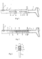
- the skirt or trousers tensioner 1 shown in the drawing consists of a central part 2 with a suspension hook 3 and a tension arm 4 arranged at each end, which has a stepped, downwardly and outwardly inclined profile 5 at its end.
- the central part 2 is formed by a U-profile, which consists of a web 6 forming the back of the bracket and the legs 7, 8 adjoining at the bottom.
- the U-profile is open at the bottom over its entire length and, in the embodiment according to FIGS. 1 to 3, has an inner abutment 9 for a compression spring 10 on both sides of the suspension hook 3, the opposite end of which is located on a step 11 of the Support arm 4 supports.
- a pin 12 is formed on the step 11 of the clamping arm.
- the tensioning arms 4 have a double-T profile, the profile in the outer area of the tensioning arm having approximately the height of the U-profile, while it is lower in the inner area, so that between the lower lying upper edge 13 and the inside of the web 6 of the U-profile, a chamber is formed which receives the compression spring 10.
- two protruding short ribs 14 are present in the area of the recessed upper edge 13 or the I-beam of the tensioning arm 4 there, which engage in two spaced-apart, aligned longitudinal slots 15 in the legs 7, 8 of the U-profile .
- the right-hand ends of the longitudinal slots 15 form an abutment for the ribs 14 acting as stops and thus limit the extension movement of the tension arm 4 under the action of the compression spring 10.
- the ends of the longitudinal slots located on the inside form a stop for the insertion movement of the tension arms 4.
- the ribs 14 can be beveled on their upper side 16, as can be seen in FIG. 3, in order to facilitate the insertion of the tensioning arms from below into the U-profile.
- the same purpose can be arranged on the inside of the legs 7, 8 weak depression 16 '( Figure 1), the width of which corresponds approximately to the width of the ribs 14 and which extends from the lower free longitudinal edge of the legs 7, 8 to the longitudinal slots 15 .
- FIG. 1 A springless design of the rock tensioner 1 is shown in FIG. It in turn has a central part 2 in the form of a U-profile which is open at the bottom and in which the two clamping arms 4 are guided.
- the middle part 2 in turn has a slot 15 in both legs for each clamping arm , but in this case the slots overlap in the middle.
- the maximum stroke of the tensioning arms 4 corresponds to the length of the slot 15, that is, due to the overlap, is greater than in the embodiment according to FIGS. 1 to 3.
- the tensioning arms 4 are arranged one above the other within the middle part 2 with narrower sections and point to the sides facing each other one rack 17 each.
- a pinion 18 is supported, which meshes with both toothed strips 17.
- a lock 19 is provided for fixing the tensioning arms 4 to a position corresponding to a certain waist width. It consists on the one hand of rows of tooth-like projections 20 on the upper side of the tensioning arm 4 shown in the drawing on the left and a locking lug 21 which extends through a recess 22 on the web of the U-section forming the central part 2.
- the locking lug 21 is seated on a resilient web 23, which has a handle 24 in the form of a pressure plate on the side opposite the latching lug 21.
- the latch 21 between the projections 20 can be raised so that the clamping arms can be moved.
- the latch 21 engages automatically between the projections 20 under the action of the spring bar 23.
- the locking lug 21 with the spring bar 23 and the handle 24 can either be in one piece with the middle part 2, in that the spring bar 23 is molded onto the web of the middle part 2.
- these components can also be retrofitted to the central part 2 as a separate part, e.g. B. be clickable.
- the central part can optionally be raised to such an extent that the handle 24 is flush with the top, as shown by broken lines 25 is.
- the spring bar 23 must be fixed in a different way within the middle part 2.
- each tension arm 4 in which slots the tension arms 4 are each guided by a guide lug 28, 29.
- the tensioning arms 4 are prestressed here by a rubber band 30 instead of by a compression spring, as shown in FIGS. 1 to 3, which, for example in the form of an endless loop, on the one hand on lugs 31 in the region of the ends of the middle part 2 and on the other hand accordingly trained projections are suspended on the sections of the clamping arms 4 lying within the central part 2.
- the elastic bands 30 act as the tension arms 4 pushing outward tension springs, against the tensile force of which the tension arms 4 can be moved to smaller waist widths.
- the longitudinal slots 26, 27 are offset at the height of the legs 7, 8 of the U-profile and overlap in the longitudinal direction of the skirt tensioner. In this way, the longitudinal slots can be made much longer, so that a correspondingly larger range of skirt widths is spanned.
- the spring can be arranged, for example, between the slots.
- a bracket 32 is indicated by dash-dotted lines in FIG. 6 in order to be able to use the skirt tensioner also as a laundry hanger.
- the exact design is shown in Figure 7.
- One leg 33 of the clamp 32 is inserted between the legs 7, 8 of the middle part 2 and engages with ribs 34, 35 in one of the longitudinal slots 26, primarily the outer ones. The clip is guided and fixed properly and can be moved along the slot will.
- the outer surface 36 of this leg 33 of the clamp 32 lies in one plane with the outside of the leg 7 of the middle part 2.
- the other leg 37 is mounted at 38 on the leg 33 and between the clamp legs a leg spring 39 wound onto the bearing 38 is effective. The leg 37 can be pressed against the middle part 2 to open the clamp 32.
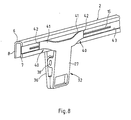
- FIG. 8 shows a modified embodiment of the clamp 32.
- deflector surfaces 40 which are inclined, are arranged on the outer leg 37 of the clamp 32, specifically at the upper end thereof, in both directions and in the direction of the extension of the central part 2 or curved webs 41 are formed, which extend from the end of the leg 37 to the central part 2.
- the webs 41 are injection-molded in one piece with the leg 37 and are designed to be slightly resilient.
- the middle part 2 can have a groove 43 on the outside of the leg 7 of the U-profile, which extends in the direction of the middle part and into which the ends 42 of the webs 41 engage flush.
- This embodiment provides the further possibility of dispensing with the leg spring 39 according to FIG. 7, in that the webs 41 are designed to be resilient in such a way that they urge the leg 37 into the closed position. Pressure on the upper end of the leg 37 opens the clip in a conventional manner.
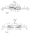
- the tensioning arms 4 are in turn guided in the longitudinal slots 15 of the central part 2 by means of ribs 14.
- the longitudinal slots 15 can extend over the entire length of the central part and the clamping arms 4 are designed to be correspondingly long, so that there is an extremely large span range.
- the clamping arms in turn have toothed strips 17 on the sides facing one another, which mesh with a centrally mounted pinion 18.
- the upper clamping arm 4 is provided in its region lying within the middle part 2 with projections 20 which extend over the adjustment range of the rock tensioner and into which a locking lug 21 of a locking device penetrating a recess in the web 6 of the middle part 2 intervenes.
- the detent 21 is part of a one-piece injection molded part, which further has a leaf spring-like snap spring 44 and a disc-like handle 45.
- a U-shaped bracket 46 is also formed, which receives the suspension hook 3 on its web and also surrounds the leaf spring 44 and the handle 45.
- the ends of the snap spring 44 are supported at 47 in the two legs of the bracket 46.
- the locking lug 21 engages between the projections 20 on the upper clamping arm 4.
- the snap spring 44 jumps into the dot-dash position in which the catch releases the tension arm 4 for adjustment to the span. If the skirt tensioner is adjusted to the skirt width, a slight pressure on the handle 45 downwards is sufficient and the snap spring 44 springs over.
- the disk-shaped handle 45 can additionally serve as an advertising and information carrier.
- an upwardly facing rock hook 48 is also arranged at the ends of the tensioning arms 4, which is spaced from above a deflector hook 49 is overlapped.
- the rock hook 48 and the deflector hook 49 can be formed in alignment with the upper edge of the tensioning arm 4, as shown on the right in FIG. 9, or on an upward extension, as shown in FIG. 9 on the left.
- the exemplary embodiment according to FIG. 10 differs from that of FIG. 9 only in the different design of the tensioning arms.
- upward and inward-facing projections 50 are formed, each of which has the rock hook 51, which is likewise open inward, at its inward-facing ends.
- the downwardly extending lugs 52 are also inclined inwards on the outside.
- the skirt loops are guided from the outside over the attachments 50 and hooked into the skirt hooks 51, the skirt loops running vertically downward and the collar of the suspended skirt not being tensioned or otherwise impaired by the attachments 52.
- a projection 53, 54 is formed in each case on the mutually facing inner sides of the legs of the middle part 2, specifically in the region of the ends.
- the projection 53 serves as a support for the right clamping arm 4, which rests on the projection 53 with its underside, while the projection 54 forms the support for the left, lower clamping arm 4.
- This tension arm lies on the projection with its upper T-beam.
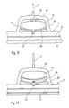
- FIG. 11 shows an embodiment in which the locking is initially designed differently than in Figure 4.
- the locking lug 21 is again formed in one piece with a push button-like handle 24, which is mounted by means of pins 55 in a recess on the central part 2 and through an inserted compression spring is held in the locking position.
- FIG. 11 shows an exploded view of a reinforcing profile 56 which is of the same shape as the U-profile of the middle part 2, that is to say also has a U-shape, but is closed on its underside by a web 57.
- the reinforcement profile 56 is inserted into the laterally open ends of the middle part 2.
- the reinforcement profile can in turn have a projection 54 as a support for the left clamping arm 4, while the right clamping arm rests on the web 57.
- FIG. 12 shows an embodiment modified compared to FIGS. 9 and 10, in which the snap spring 44 acting in two directions is replaced by a leaf spring 58 which only acts on one side and which always urges the catch 21 into the catch position.
- the handle 45 which in turn can serve as an advertising and information carrier, is also in one piece with the leaf spring 58 and the detent 21 and is mounted at 47 in the bracket 46 spanning it.
- the spring action can be supported by a further leaf spring 59, which is integrally formed on the bracket 46 and acts on the handle 45. If necessary, this spring alone is also sufficient and the part 58 merely forms a guide for the handle 45.
- the catch always snaps into the catch position as soon as the handle is released. Adjustment of the clamping arms to larger spans is still possible, since the strip with the projections 20 has a sawtooth-like profile.
Landscapes
- Holders For Apparel And Elements Relating To Apparel (AREA)
Priority Applications (1)
| Application Number | Priority Date | Filing Date | Title |
|---|---|---|---|
| AT89110511T ATE96627T1 (de) | 1988-06-15 | 1989-06-10 | Rock- oder hosenspanner. |
Applications Claiming Priority (4)
| Application Number | Priority Date | Filing Date | Title |
|---|---|---|---|
| DE3820280 | 1988-06-15 | ||
| DE3820280 | 1988-06-15 | ||
| DE3913003 | 1989-04-20 | ||
| DE3913003A DE3913003A1 (de) | 1988-06-15 | 1989-04-20 | Rock- oder hosenspanner |
Publications (3)
| Publication Number | Publication Date |
|---|---|
| EP0346780A2 true EP0346780A2 (fr) | 1989-12-20 |
| EP0346780A3 EP0346780A3 (fr) | 1991-10-23 |
| EP0346780B1 EP0346780B1 (fr) | 1993-11-03 |
Family
ID=25869125
Family Applications (1)
| Application Number | Title | Priority Date | Filing Date |
|---|---|---|---|
| EP89110511A Expired - Lifetime EP0346780B1 (fr) | 1988-06-15 | 1989-06-10 | Tendeur de pantalons ou de jupes |
Country Status (2)
| Country | Link |
|---|---|
| EP (1) | EP0346780B1 (fr) |
| DE (2) | DE3913003A1 (fr) |
Cited By (9)
| Publication number | Priority date | Publication date | Assignee | Title |
|---|---|---|---|---|
| WO1990010408A1 (fr) * | 1989-03-10 | 1990-09-20 | Braitrim (U.K.) Limited | Cintre extensible |
| EP0482509A1 (fr) * | 1990-10-22 | 1992-04-29 | Coronet-Kunststoffwerk GmbH | Tendeur |
| GB2252902A (en) * | 1991-02-25 | 1992-08-26 | Pendy Plastic Prod | Garment hanger |
| EP0578370A1 (fr) * | 1992-07-04 | 1994-01-12 | Mainetti (Uk) Ltd. | Cintre |
| WO1994026155A1 (fr) * | 1993-05-13 | 1994-11-24 | Karner & Co Ab | Cintre |
| GB2291343A (en) * | 1992-06-16 | 1996-01-24 | Mainetti | An expandable garment hanger |
| GB2296859A (en) * | 1995-01-12 | 1996-07-17 | Nick Andrew Lewis | Adjustable garment hanger |
| EP1043251A3 (fr) * | 1998-11-20 | 2001-05-16 | Wolfgang Paulsen | Procédé, dispositif et cintre transporteur pour le transfer automatique de cintres |
| CN108771450A (zh) * | 2018-05-06 | 2018-11-09 | 潘建杰 | 一种裤撑 |
Families Citing this family (4)
| Publication number | Priority date | Publication date | Assignee | Title |
|---|---|---|---|---|
| DE9319408U1 (de) * | 1993-12-17 | 1994-02-24 | Coronet-Kunststoffwerk Gmbh, 64689 Grasellenbach | Spann-Kleiderbügel |
| DE9402100U1 (de) * | 1994-02-08 | 1994-04-14 | Coronet-Kunststoffwerk Gmbh, 64689 Grasellenbach | Kleiderbügel |
| DE9416773U1 (de) * | 1994-07-14 | 1995-11-16 | Mawa - Metallwarenfabrik Wagner Gmbh, 85276 Pfaffenhofen | Kleiderbügel verstellbarer Spannweite |
| DE29607431U1 (de) * | 1996-04-24 | 1996-07-11 | Coronet-Kunststoffwerk Gmbh, 64689 Grasellenbach | Kleiderbügel |
Family Cites Families (5)
| Publication number | Priority date | Publication date | Assignee | Title |
|---|---|---|---|---|
| US2814426A (en) * | 1954-10-12 | 1957-11-26 | Miller Milan | Coat hanger |
| FR1180269A (fr) * | 1957-07-29 | 1959-06-03 | Porte-pantalon | |
| SE306604B (fr) * | 1964-03-03 | 1968-12-02 | S Samuelsson | |
| SE453631B (sv) * | 1985-02-18 | 1988-02-22 | Karner & Co Ab | Kjol- eller byxhengare |
| GB8724851D0 (en) * | 1987-10-23 | 1987-11-25 | Braitrim London Ltd | Expandable garment hanger |
-
1989
- 1989-04-20 DE DE3913003A patent/DE3913003A1/de not_active Withdrawn
- 1989-06-10 EP EP89110511A patent/EP0346780B1/fr not_active Expired - Lifetime
- 1989-06-10 DE DE89110511T patent/DE58906077D1/de not_active Expired - Fee Related
Cited By (14)
| Publication number | Priority date | Publication date | Assignee | Title |
|---|---|---|---|---|
| AU658731B2 (en) * | 1989-03-10 | 1995-04-27 | Braitrim (U.K.) Limited | Expandable garment hanger |
| WO1990010408A1 (fr) * | 1989-03-10 | 1990-09-20 | Braitrim (U.K.) Limited | Cintre extensible |
| AU633059B2 (en) * | 1989-03-10 | 1993-01-21 | Braitrim (U.K.) Limited | Expandable garment hanger |
| EP0482509A1 (fr) * | 1990-10-22 | 1992-04-29 | Coronet-Kunststoffwerk GmbH | Tendeur |
| GB2252902A (en) * | 1991-02-25 | 1992-08-26 | Pendy Plastic Prod | Garment hanger |
| GB2252902B (en) * | 1991-02-25 | 1995-07-12 | Pendy Plastic Prod | Garment hanger |
| GB2291343A (en) * | 1992-06-16 | 1996-01-24 | Mainetti | An expandable garment hanger |
| GB2291343B (en) * | 1992-06-16 | 1996-04-03 | Mainetti | Garment hanger |
| EP0578370A1 (fr) * | 1992-07-04 | 1994-01-12 | Mainetti (Uk) Ltd. | Cintre |
| WO1994026155A1 (fr) * | 1993-05-13 | 1994-11-24 | Karner & Co Ab | Cintre |
| GB2296859A (en) * | 1995-01-12 | 1996-07-17 | Nick Andrew Lewis | Adjustable garment hanger |
| EP1043251A3 (fr) * | 1998-11-20 | 2001-05-16 | Wolfgang Paulsen | Procédé, dispositif et cintre transporteur pour le transfer automatique de cintres |
| CN108771450A (zh) * | 2018-05-06 | 2018-11-09 | 潘建杰 | 一种裤撑 |
| CN108771450B (zh) * | 2018-05-06 | 2023-12-01 | 潘建杰 | 一种裤撑 |
Also Published As
| Publication number | Publication date |
|---|---|
| EP0346780A3 (fr) | 1991-10-23 |
| EP0346780B1 (fr) | 1993-11-03 |
| DE3913003A1 (de) | 1989-12-21 |
| DE58906077D1 (de) | 1993-12-09 |
Similar Documents
| Publication | Publication Date | Title |
|---|---|---|
| EP0346780B1 (fr) | Tendeur de pantalons ou de jupes | |
| DE69210341T2 (de) | Aufhänger | |
| DE2825724B2 (de) | Vorrichtung zur Lagerung und Schaustellung von Warenpäckchen | |
| DE2427106A1 (de) | Behaelter zur aufbewahrung von magnetbandkassetten | |
| EP0106233A2 (fr) | Sangle, en particulier sangle de tension pour meuble | |
| EP0448003A1 (fr) | Dispositif de fixation et/ou de retenue pour voies à rouleaux sur rails de support ou similaires, notamment pour couloirs de roulement | |
| DE1457473B1 (de) | Handgriff für Tragbeutel | |
| DE9209667U1 (de) | Verschluß zur zentralen Ver- und Entriegelung von Schubladen | |
| DE29614006U1 (de) | Verbindung zwischen Rolladenkasten und Fensterrahmen-Schenkel | |
| EP0670135B1 (fr) | Cintre | |
| DE19828718A1 (de) | Rasteinrichtung zum lösbaren Befestigen von Schubkästen, Auszügen, Schüben o. dgl. an einer Führungsschiene | |
| DE4435672A1 (de) | Spann-Kleiderbügel | |
| EP0289714A1 (fr) | Cintre pour vêtements | |
| DE3109561C2 (de) | Wechselbildhalterung | |
| DE8116612U1 (de) | Kleiderbügel in Form eines Rockspanners | |
| CH698346A2 (de) | Schlaufengleiter mit Einfädelschlitz. | |
| EP0482509A1 (fr) | Tendeur | |
| DE1679110C3 (de) | Spanner für Hosen, Röcke und dergleichen mit parallel geführten, rohrförmigen Tragarmen | |
| EP1336363B1 (fr) | Cintre pour vêtements et linge | |
| DE4407990A1 (de) | Tragriemenbefestigung für Kameras | |
| DE1457473C (de) | Handgriff fur Tragbeutel | |
| DE2543857C2 (de) | Kleiderbügel | |
| DE20000078U1 (de) | Vorrichtung zum Auf- und Abhängen von Vorhängen, sowie Vorhanghäkchen für diese Vorrichtung | |
| DE10000100C1 (de) | Vorrichtung zum Auf- und Abhängen von Vorhängen, sowie Vorhanghäkchen für diese Vorrichtung | |
| DE20216373U1 (de) | Wäschebügel, insbesondere für String-Tanga |
Legal Events
| Date | Code | Title | Description |
|---|---|---|---|
| PUAI | Public reference made under article 153(3) epc to a published international application that has entered the european phase |
Free format text: ORIGINAL CODE: 0009012 |
|
| AK | Designated contracting states |
Kind code of ref document: A2 Designated state(s): AT BE CH DE FR GB IT LI NL SE |
|
| ITCL | It: translation for ep claims filed |
Representative=s name: DR. ING. A. RACHELI & C. |
|
| GBC | Gb: translation of claims filed (gb section 78(7)/1977) | ||
| EL | Fr: translation of claims filed | ||
| TCNL | Nl: translation of patent claims filed | ||
| GBC8 | Gb: translation of claims filed (gb section 80(3)/1977) | ||
| PUAL | Search report despatched |
Free format text: ORIGINAL CODE: 0009013 |
|
| AK | Designated contracting states |
Kind code of ref document: A3 Designated state(s): AT BE CH DE FR GB IT LI NL SE |
|
| 17P | Request for examination filed |
Effective date: 19911121 |
|
| 17Q | First examination report despatched |
Effective date: 19920821 |
|
| GRAA | (expected) grant |
Free format text: ORIGINAL CODE: 0009210 |
|
| AK | Designated contracting states |
Kind code of ref document: B1 Designated state(s): AT BE CH DE FR GB IT LI NL SE |
|
| PG25 | Lapsed in a contracting state [announced via postgrant information from national office to epo] |
Ref country code: BE Effective date: 19931103 Ref country code: FR Effective date: 19931103 Ref country code: GB Effective date: 19931103 Ref country code: NL Effective date: 19931103 Ref country code: SE Effective date: 19931103 Ref country code: IT Free format text: LAPSE BECAUSE OF FAILURE TO SUBMIT A TRANSLATION OF THE DESCRIPTION OR TO PAY THE FEE WITHIN THE PRE;WARNING: LAPSES OF ITALIAN PATENTS WITH EFFECTIVE DATE BEFORE 2007 MAY HAVE OCCURRED AT ANY TIME BEFORE 2007. THE CORRECT EFFECTIVE DATE MAY BE DIFFERENT FROM THE ONE RECORDED.SCRIBED TIME-LIMIT Effective date: 19931103 |
|
| REF | Corresponds to: |
Ref document number: 96627 Country of ref document: AT Date of ref document: 19931115 Kind code of ref document: T |
|
| REF | Corresponds to: |
Ref document number: 58906077 Country of ref document: DE Date of ref document: 19931209 |
|
| EN | Fr: translation not filed | ||
| NLV1 | Nl: lapsed or annulled due to failure to fulfill the requirements of art. 29p and 29m of the patents act | ||
| GBV | Gb: ep patent (uk) treated as always having been void in accordance with gb section 77(7)/1977 [no translation filed] |
Effective date: 19931103 |
|
| PGFP | Annual fee paid to national office [announced via postgrant information from national office to epo] |
Ref country code: AT Payment date: 19940614 Year of fee payment: 6 |
|
| PGFP | Annual fee paid to national office [announced via postgrant information from national office to epo] |
Ref country code: DE Payment date: 19940628 Year of fee payment: 6 |
|
| PGFP | Annual fee paid to national office [announced via postgrant information from national office to epo] |
Ref country code: CH Payment date: 19940830 Year of fee payment: 6 |
|
| PLBE | No opposition filed within time limit |
Free format text: ORIGINAL CODE: 0009261 |
|
| STAA | Information on the status of an ep patent application or granted ep patent |
Free format text: STATUS: NO OPPOSITION FILED WITHIN TIME LIMIT |
|
| 26N | No opposition filed | ||
| PG25 | Lapsed in a contracting state [announced via postgrant information from national office to epo] |
Ref country code: AT Effective date: 19950610 |
|
| PG25 | Lapsed in a contracting state [announced via postgrant information from national office to epo] |
Ref country code: LI Effective date: 19950630 Ref country code: CH Effective date: 19950630 |
|
| REG | Reference to a national code |
Ref country code: CH Ref legal event code: PL |
|
| PG25 | Lapsed in a contracting state [announced via postgrant information from national office to epo] |
Ref country code: DE Effective date: 19960301 |