EP0346945A2 - Appareil de remplissage d'un ouvrage encoché - Google Patents
Appareil de remplissage d'un ouvrage encoché Download PDFInfo
- Publication number
- EP0346945A2 EP0346945A2 EP89114684A EP89114684A EP0346945A2 EP 0346945 A2 EP0346945 A2 EP 0346945A2 EP 89114684 A EP89114684 A EP 89114684A EP 89114684 A EP89114684 A EP 89114684A EP 0346945 A2 EP0346945 A2 EP 0346945A2
- Authority
- EP
- European Patent Office
- Prior art keywords
- notches
- block
- filler material
- bottom portion
- glass
- Prior art date
- Legal status (The legal status is an assumption and is not a legal conclusion. Google has not performed a legal analysis and makes no representation as to the accuracy of the status listed.)
- Granted
Links
- 239000011521 glass Substances 0.000 claims abstract description 107
- 239000000463 material Substances 0.000 claims abstract description 57
- 239000000945 filler Substances 0.000 claims abstract description 24
- 230000002463 transducing effect Effects 0.000 claims description 45
- 239000002131 composite material Substances 0.000 claims description 9
- 239000011162 core material Substances 0.000 claims description 6
- 229910001220 stainless steel Inorganic materials 0.000 claims description 4
- 239000010935 stainless steel Substances 0.000 claims description 4
- OKTJSMMVPCPJKN-UHFFFAOYSA-N Carbon Chemical compound [C] OKTJSMMVPCPJKN-UHFFFAOYSA-N 0.000 claims description 3
- 229910002804 graphite Inorganic materials 0.000 claims description 3
- 239000010439 graphite Substances 0.000 claims description 3
- 238000000034 method Methods 0.000 description 45
- 239000000696 magnetic material Substances 0.000 description 17
- 230000008018 melting Effects 0.000 description 9
- 238000002844 melting Methods 0.000 description 9
- 238000004804 winding Methods 0.000 description 9
- 229910000859 α-Fe Inorganic materials 0.000 description 9
- 238000004519 manufacturing process Methods 0.000 description 8
- 238000005520 cutting process Methods 0.000 description 6
- 230000008901 benefit Effects 0.000 description 4
- 230000008569 process Effects 0.000 description 4
- 239000007789 gas Substances 0.000 description 3
- 238000003754 machining Methods 0.000 description 3
- 238000004544 sputter deposition Methods 0.000 description 3
- 230000001154 acute effect Effects 0.000 description 2
- 238000006243 chemical reaction Methods 0.000 description 2
- 239000004519 grease Substances 0.000 description 2
- 230000001771 impaired effect Effects 0.000 description 2
- 230000035699 permeability Effects 0.000 description 2
- 230000001681 protective effect Effects 0.000 description 2
- 230000009467 reduction Effects 0.000 description 2
- 230000000630 rising effect Effects 0.000 description 2
- 125000006850 spacer group Chemical group 0.000 description 2
- 241001465754 Metazoa Species 0.000 description 1
- 229910000831 Steel Inorganic materials 0.000 description 1
- 239000013078 crystal Substances 0.000 description 1
- 238000000151 deposition Methods 0.000 description 1
- 230000008021 deposition Effects 0.000 description 1
- 238000005137 deposition process Methods 0.000 description 1
- 229910003460 diamond Inorganic materials 0.000 description 1
- 239000010432 diamond Substances 0.000 description 1
- 238000009792 diffusion process Methods 0.000 description 1
- 230000000694 effects Effects 0.000 description 1
- 239000012777 electrically insulating material Substances 0.000 description 1
- 238000005429 filling process Methods 0.000 description 1
- 238000000227 grinding Methods 0.000 description 1
- 230000002427 irreversible effect Effects 0.000 description 1
- 238000003801 milling Methods 0.000 description 1
- 239000012299 nitrogen atmosphere Substances 0.000 description 1
- 239000012811 non-conductive material Substances 0.000 description 1
- 230000035515 penetration Effects 0.000 description 1
- 238000005498 polishing Methods 0.000 description 1
- 239000010959 steel Substances 0.000 description 1
Images





Classifications
-
- G—PHYSICS
- G11—INFORMATION STORAGE
- G11B—INFORMATION STORAGE BASED ON RELATIVE MOVEMENT BETWEEN RECORD CARRIER AND TRANSDUCER
- G11B5/00—Recording by magnetisation or demagnetisation of a record carrier; Reproducing by magnetic means; Record carriers therefor
- G11B5/127—Structure or manufacture of heads, e.g. inductive
-
- B—PERFORMING OPERATIONS; TRANSPORTING
- B29—WORKING OF PLASTICS; WORKING OF SUBSTANCES IN A PLASTIC STATE IN GENERAL
- B29C—SHAPING OR JOINING OF PLASTICS; SHAPING OF MATERIAL IN A PLASTIC STATE, NOT OTHERWISE PROVIDED FOR; AFTER-TREATMENT OF THE SHAPED PRODUCTS, e.g. REPAIRING
- B29C70/00—Shaping composites, i.e. plastics material comprising reinforcements, fillers or preformed parts, e.g. inserts
- B29C70/68—Shaping composites, i.e. plastics material comprising reinforcements, fillers or preformed parts, e.g. inserts by incorporating or moulding on preformed parts, e.g. inserts or layers, e.g. foam blocks
- B29C70/74—Moulding material on a relatively small portion of the preformed part, e.g. outsert moulding
- B29C70/745—Filling cavities in the preformed part
-
- B—PERFORMING OPERATIONS; TRANSPORTING
- B29—WORKING OF PLASTICS; WORKING OF SUBSTANCES IN A PLASTIC STATE IN GENERAL
- B29C—SHAPING OR JOINING OF PLASTICS; SHAPING OF MATERIAL IN A PLASTIC STATE, NOT OTHERWISE PROVIDED FOR; AFTER-TREATMENT OF THE SHAPED PRODUCTS, e.g. REPAIRING
- B29C43/00—Compression moulding, i.e. applying external pressure to flow the moulding material; Apparatus therefor
- B29C43/02—Compression moulding, i.e. applying external pressure to flow the moulding material; Apparatus therefor of articles of definite length, i.e. discrete articles
- B29C43/18—Compression moulding, i.e. applying external pressure to flow the moulding material; Apparatus therefor of articles of definite length, i.e. discrete articles incorporating preformed parts or layers, e.g. compression moulding around inserts or for coating articles
-
- G—PHYSICS
- G11—INFORMATION STORAGE
- G11B—INFORMATION STORAGE BASED ON RELATIVE MOVEMENT BETWEEN RECORD CARRIER AND TRANSDUCER
- G11B5/00—Recording by magnetisation or demagnetisation of a record carrier; Reproducing by magnetic means; Record carriers therefor
- G11B5/127—Structure or manufacture of heads, e.g. inductive
- G11B5/187—Structure or manufacture of the surface of the head in physical contact with, or immediately adjacent to the recording medium; Pole pieces; Gap features
-
- G—PHYSICS
- G11—INFORMATION STORAGE
- G11B—INFORMATION STORAGE BASED ON RELATIVE MOVEMENT BETWEEN RECORD CARRIER AND TRANSDUCER
- G11B5/00—Recording by magnetisation or demagnetisation of a record carrier; Reproducing by magnetic means; Record carriers therefor
- G11B5/127—Structure or manufacture of heads, e.g. inductive
- G11B5/187—Structure or manufacture of the surface of the head in physical contact with, or immediately adjacent to the recording medium; Pole pieces; Gap features
- G11B5/193—Structure or manufacture of the surface of the head in physical contact with, or immediately adjacent to the recording medium; Pole pieces; Gap features the pole pieces being ferrite or other magnetic particles
-
- G—PHYSICS
- G11—INFORMATION STORAGE
- G11B—INFORMATION STORAGE BASED ON RELATIVE MOVEMENT BETWEEN RECORD CARRIER AND TRANSDUCER
- G11B5/00—Recording by magnetisation or demagnetisation of a record carrier; Reproducing by magnetic means; Record carriers therefor
- G11B5/127—Structure or manufacture of heads, e.g. inductive
- G11B5/29—Structure or manufacture of unitary devices formed of plural heads for more than one track
- G11B5/295—Manufacture
-
- Y—GENERAL TAGGING OF NEW TECHNOLOGICAL DEVELOPMENTS; GENERAL TAGGING OF CROSS-SECTIONAL TECHNOLOGIES SPANNING OVER SEVERAL SECTIONS OF THE IPC; TECHNICAL SUBJECTS COVERED BY FORMER USPC CROSS-REFERENCE ART COLLECTIONS [XRACs] AND DIGESTS
- Y10—TECHNICAL SUBJECTS COVERED BY FORMER USPC
- Y10T—TECHNICAL SUBJECTS COVERED BY FORMER US CLASSIFICATION
- Y10T29/00—Metal working
- Y10T29/49—Method of mechanical manufacture
- Y10T29/49002—Electrical device making
- Y10T29/4902—Electromagnet, transformer or inductor
- Y10T29/49021—Magnetic recording reproducing transducer [e.g., tape head, core, etc.]
- Y10T29/49032—Fabricating head structure or component thereof
- Y10T29/49048—Machining magnetic material [e.g., grinding, etching, polishing]
-
- Y—GENERAL TAGGING OF NEW TECHNOLOGICAL DEVELOPMENTS; GENERAL TAGGING OF CROSS-SECTIONAL TECHNOLOGIES SPANNING OVER SEVERAL SECTIONS OF THE IPC; TECHNICAL SUBJECTS COVERED BY FORMER USPC CROSS-REFERENCE ART COLLECTIONS [XRACs] AND DIGESTS
- Y10—TECHNICAL SUBJECTS COVERED BY FORMER USPC
- Y10T—TECHNICAL SUBJECTS COVERED BY FORMER US CLASSIFICATION
- Y10T29/00—Metal working
- Y10T29/49—Method of mechanical manufacture
- Y10T29/49002—Electrical device making
- Y10T29/4902—Electromagnet, transformer or inductor
- Y10T29/49021—Magnetic recording reproducing transducer [e.g., tape head, core, etc.]
- Y10T29/49032—Fabricating head structure or component thereof
- Y10T29/49055—Fabricating head structure or component thereof with bond/laminating preformed parts, at least two magnetic
- Y10T29/49057—Using glass bonding material
Definitions
- the invention relates to apparatus for filling notches provided in a notched workpiece, and particularly for filling a notched block of magnetic core material during the manufacture of magnetic transducers for narrow track recording and/or playback and it is particularly useful with respect to transducers made of hard, brittle magnetic materials.
- Magnetic transducers having notched poles to reduce recording track width are well known in the art.
- the notches are generally fitted with a suitable nonmagnetic material, such as glass to avoid chipping and granular pullouts of the magnetic material in the transducing gap area.
- high temperature glasses which have compatible mechanical properties, including wear rate with the magnetic material.
- the melting temperature of high temperature glasses which is generally around 900° C, exceeds a critical temperature at which the permeability and other magnetic characteristics of the magnetic material are impaired. It is a well known undesirable phenomenon that when these glasses are utilized in transducers made of ferrite material at a temperature above their melting point, diffusion of glass into the ferrite takes place. The latter phenomenon is irreversible and therefore transducer efficiency is thereby permanently reduced.
- low temperature glasses are known to have a relatively high lead content and when heated to their melting temperature they may chemically react with the particular magnetic material thereby impairing its magnetic properties.
- an apparatus for filling notches provided in a workpiece with a soft filler material having a viscosity similar to glasses comprising: a bottom portion having a groove for accommodating a workpiece having a notched top surface; and a top portion having a lower surface cooperating with said bottom portion and having at least one discrete location for applying a concentrated pressure to said soft filler material, said lower surface being positioned outside said notches in said workpiece when said workpiece is inserted in said groove, to enhance flow of said soft filler material into said notches when said top portion is assembled with said bottom portion, the filler material being disposed therebetween.
- an apparatus for use in filling notches in a surface of a block of magnetic core material with a soft filler material having a viscosity similar to glasses comprising: a bottom portion having at least one groove for accommodating at least one such block of magnetic transducer core material; and a top portion cooperating with said bottom portion and having a serrated lower surface adapted apply a concentrated pressure to said soft filler material and being positioned outside said notches in said block when said block is inserted in said groove and said top portion is assembled with said bottom portion with said soft filler material disposed therebetween, to enhance flow of said soft filler material into said notches.
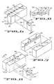
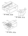
- FIGS 1 to 12 Examples of “prefilling” methods for transducers or “prefilled” transducers respectively are shown in Figures 1 to 12 in the attached drawings. In these transducers the notches are filled with a nonmagnetic material prior to bonding the transducing gap.
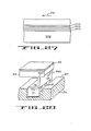
- Figures 13 to 27 show a "postfilling” method or “postfilled” transducers respectively, since the transducing gaps are first bonded and the notches are filled with a suitable nonmagnetic material thereafter.
- a block 10 of magnetic material for example ferrite
- the size of the block is, for example, 3.175 x 1.57 x 7.62 mm.
- a plurality of spaced parallel notches 12 is cut along a longitudinal edge 14 into block 10, intercepting adjacent perpendicular surfaces 16 and 18 thereof.
- Notches 12 are cut in a well known manner, for example utilizing an abrasive wheel (not shown) as it is described for example in the above mentioned patents numbers 3.813,643 and 3,845,550.
- the notches 12 define magnetic poles 20 therebetween having a precise width t in the direction of edge 14 to define a desired transducing gap width, also referred to as track width of the resulting trrans- ducer structure as it will follow from further description.
- a desired transducing gap width also referred to as track width of the resulting trrans- ducer structure as it will follow from further description.
- respective pairs of notches 12 are spaced from each other at a distance greater than t, thereby forming lands 22.
- Lands 22 serve to provide sufficient space for accommodating a cutting tool such as a saw blade utilized for slicing individual transducers from block 10 in a well known manner.
- Figure 2 shows a subsequent method step of glass filling the notches 12 of block 10.
- Figure 2 shows an exploded view of a preferred embodiment of fixture 24 utilized for the process of glass filling the notches 12.
- Fixture 24 is made preferably of graphite and/or stainless steel or other suitable material which withstands temperatures applied thereto during the following manufacturing process.
- Fixture 24 is preferably made by machining, for example utilizing a milling machine and employing machining techniques well known in the art.
- Fixture 24 has a bottom portion 26 and a top portion 31 made to fit over the bottom portion 26 when assembled therwith.
- Portion 26 is provided with a first set of parallel grooves 28 to snuggly accomodate a number of notched blocks 10.
- a second set of parallel grooves 30 is provided to accommodate glass strips 38 preferably made of a high temperature glass, for example number 9025, made by Corning Glass Works.
- a longitudinal recess or step 29 is formed to provide space to accommodate flow of excess glass during the glass filling process as it will follow from further description.
- the top portion 31 of fixture 24 comprises a block 34, having a lower surface 36 provided with a plurality of parallel longitudinal serrations 37.
- a weight 32 preferably in the form of a plate extends over an upper surfce 33 of block 34 opposite the serrated surface 36.
- the weight 32 is evenly distributed over the upper surface 33 of block 34.
- the serrated block 34 is preferably made of graphite and plate 32 of steel. It will be understood that alternatively weight 32 may be applied to block 34 in any other suitable form.
- the top portion 31 of fixture 24 is turned by 180 ° C in Figure 2 to reveal the serrated surface 36 thereof.
- FIG 2A shows an enlarged fragmentary view of a portion of serrations 37 indicated by the line 2A in Figure 2.
- the number and shape of the above described serrations is not critical when utilized in accordance with the method of the invention and that any other suitable shape, size or number of serrations may be utilized. It has been observed that while just one such serration 37 may be sufficient for example when utilizing relatively short strips of glass 38 over a corresponding short block 10, the process is accelerated when a plurality of serrations is utilized.
- one or more notched blocks 10 are inserted into grooves 28 having notches 12 aligned along the stepped side walls 29 and the bottom of grooves 30 to obtain intimate contact with the glass strip 38 when inserted in grooves 30.
- those glass contacting areas of fixture 24 which are made of stainless steel are preferably coated with a high temperature grease, for example type C-102, manufactured by FEL-PRO Incorporated, and baked at about 400 C for about 30 minutes as directed by manufacturer and as well known in the art.
- Glass strips 38 are then inserted into grooves 30 and the bottom portion 26 is thereafter assembled with the top portion 31 in such a way that edges of serrations 37 are in contact with the top surface 41 of glass strips 38, as best shown in the enlarged fragmentary, partially perspective and partially cross sectional view of Figure 3 taken along line 3 of Figure 2.
- the assembled fixture 24 is then placed in an oven, as it is well known in the art, where it is heated above the softening temperature of the glass 38 but below the melting temperature thereof.
- the temperature of the oven is preferably selected at 750 C.
- the present invention facilitates glass flow at a selected relatively low temperature which is over its softening temperature but below its melting temperature, by applying thereto concentrated pressure at discrete locations as it is described below.
- the weight 32 applied to block 34 urges serrations 37 against the softened surface of the glass strips 38.
- the projecting edges of serrations 37 provide discrete locations of concentrated high pressure over the glass surface 41.
- glass flow into the notches 12 is enchanced.
- the notches 12 are thereby filled with the glass while excess glass flows into free areas provided within the fixture 24, such as grooves 29.
- grooves 28 be dimensioned to snugly accommodate blocks 10 therein.
- blocks 10 are removed from fixture 24 and block 1 is lapped to remove excess glass from the surfaces thereof.
- a longitudinal groove 40 is formed in one block 10 in a well known manner for example by machine grinding, in the direction of edge 14 inwardly of surface 18, immediately below and intercepting the glass filled notches 12. Groove 40 serves to provide winding windows as it is well known in the art and will follow from further description.
- Surface 18 is then polished to obtain a flatness necessary for a transducing gap plane as well known.
- a second block 42 corresponding to block 10 is prepared in the above described manner with the exception of groove 40.
- a suitable nonmagnetic transducing gap forming material is then deposited at corresponding gap planes 18 and 46 of respective blocks 10, 42, for example Corning Glass number 9741 utilizing well known vacuum sputtering techniques.
- the combined thicknesses of the sputtered layers correspond to a desired transducing gap length which in the preferred embodiment may range between 0.38 and 5.08 microns.
- Blocks 10, 42 are then assembled as shown in Figures 4 and 5 and held together with corresponding transducing gap surfaces 18, 46 abutting and with the corresponding magnetic poles 20 precisely aligned to avoid mismatch.
- the thusly assembled blocks 10, 42 are held in a suitable holding fixture (not shown) as it is well known in the art, placed in an oven and glass bonded at a temperature approximately 700 C as directed by the manufacturer of the particular glass utilized.
- the bonded blocks 10, 42 are then removed from the holding fixture and subsequently they are sliced into a plurality of individual transducers 50, each having a width w, as indicated by parallel lines 48 in Figure 5.
- the slicing operation is performed for example by a diamond saw blade which passes through the glass filled notches, also referred to as pockets 12 at lines 48.
- the transducing gap width t of each resulting transducer 50 as best shown in Figure 6 is defined between respective laterally extending pockets 12 at opposite sides of the transducing gap defining poles 20.
- the transducer 50 is then lapped at opposite parallel planar surfaces 52, 54 to obtain a transducer width w which has been reduced with respect to width w shown in Figure 5.
- each transducer 50 may be contoured to obtain a desired contour of the transducer-to-magnetic medium surface 56 and a desired gap depth, respectively as it is well known in the art.
- transducing windings (not shown) are wound thereon extending through the winding window 40, in a well known manner.
- Figures 7 and 9 of the attached drawings show method steps for manufacturing alternative prefilled transducers. It will be appreciated that only those steps which differ from the previously described ones will be described in detail to avoid repetition.
- two corresponding blocks 60, 62 of magnetic material similar to previously described blocks 10, 42 of Figure 4 are formed and provided with spaced parallel notches 64, 68 similar to notches 12, 44 in the previously described manner.
- adjacent notches 64, 68 respectively are equidistantly spaced from each other, forming a plurality of corresponding lands 70, 72 between them.
- the thusly formed notches 64, 68 of the corresponding blocks 60, 62 are then filled preferably with a high temperature glass, utilizing the previously described method steps as shown in Figures 2 and 3.
- a longitudinal groove 72 is provided in block 60 inwardly of a transducing gap forming surface 74 in a manner similar to forming groove 40 of Figure 4. It will be understood by those skilled in the art that a second groove (not shown) corresponding to and confronting groove 72 may be provided in block 62, if desired, to obtain additional space for transducing windings.
- blocks 60, 62 are assembled with these respective surfaces 74, 76 abutting as it is shown in Figures 7 and 8.
- each resulting transducer 80 has its transducing gap width m defined by abutting glass pockets 64, 68 on one side and by the lateral surface 84 of the transducer 80 on the other side. Therefore in this embodiment the resulting transducing gap width m may be controlled by the final lapping step at lateral surface 84.
- Figure 10 shows two corresponding blocks 10, 90 of magnetic material.
- Block 10 is prepared in a manner similar to that previously described with reference to Figures 1 to 4, that is, notched, glass filled and provided with a longitudinal groove in accordance with the above disclosed method steps.
- a second block 90 preferably of the same magnetic material as block 10 is prepared, having overall dimensions corresponding to those of block 10, but notches or grooves are not provided therein.
- the corresponding blocks 10, 90 are lapped and polished at confronting surfaces 18, 92 to obtain respective transducing gap planes and subsequently a suitable transducing gap material is deposited thereon as it has been described in the foregoing disclosure.
- the blocks 10, 90 are then assembled and held together with surfaces 18, 92 abutting and subsequently glass bonded as described before.
- the thusly obtained composite block 10, 90 is then sliced through the glass filled notches 12 as indicated by parallel lines 94 in Figure 11 to obtain a plurality of individual transducers 96, in the previously disclosed manner.
- transducing gap width or track width t of transducer 96 is defined between two adjacent glass pockets 12 provided in block 10 as above described with reference to Figure 1, the embodiment of Figures 10 to 12 has the advantage that the confronting magnetic poles 97, 99 of blocks 10, 90 do not need to be precisely aligned at the abutting surfaces 18, 92 to obtain precise alignment of confronting magnetic poles 97, 99 as shown in Figure 12.
- the thusly sliced transducers 96 are then lapped at opposite lateral planar surfaces 98, 100 to reduce the width w of the originally sliced transducer core to a desired transducer width w and they are subsequently contoured to obtain a desired transducer-to-medium surface 102 as well known.
- the transducers manufactured utilizing the prefilling method have their transducing gaps formed after the track width reducing notches have been filled.
- This method has the advantage of not causing possible damage to the glass bonded transducing gaps during the heat-requiring notch filling steps.
- the latter transducers have the disadvantage of a possible misalignment between transducing pole pieces when the confronting notched blocks are not precisely aligned. The latter disadvantage is eliminated by the postfilling method as will now be described below with reference to Figures 13 to 22, respectively.
- Figure 13 shows two corresponding blocks 110, 112 of magnetic material, for example ferrite, which are prepared in a similar manner as previously described with respect to block 80 of Figure 10.
- a longitudinal groove 114 is formed at least in one block 110 as well known to obtain winding windows.
- a layer of suitable nonmagnetic transducing gap forming material, for example glass is provided on smoothly lapped corresponding confronting surfaces 116, 118, for example by a well known deposition process, preferably sputtering.
- Corning Glass number 9741 is utilized which has a bonding temperature of 700 °C.
- the corresponding blocks 110, 112 are then assembled with confronting surfaces 116, 118 abutting as shown in figure 1 and bonded together utilizing known techniques.
- a plurality of spaced parallel notches or grooves 120 is then cut into the resulting bonded blocks 112 inwardly of an upper surface 121 thereof, preferably having a depth varying at a selected chamfer angle A preferably less than 3 degrees, as it is shown by lines 124 in Figure 15.
- the grooves 120 are cut in a well known manner for example by tilting the upper surface 121 with respect to the plane in which the abrasive wheel operates.
- Each pair of adjacent grooves or notches 120 forms a pair of confronting magnetic poles 122 which poles in turn define a transducing gap 126 therebetween.
- the width k of transducing gap 126 is defined by the spacing of adjacent grooves 120.
- Each pair of grooves 120 is spaced from an adjacent pair to form lands 121' providing sufficient space for a cutting tool, such as a saw blade (not shown), which is utilized for slicing individual transducers from the block 113, in accordance with further method steps.
- a cutting tool such as a saw blade (not shown)
- One or more thusly obtained grooved blocks 113 of Figure 15 are inserted into a suitable fixture such as shown at 128 in Figure 16.
- Blocks 113 are inserted therein having grooves 120 facing upwards as shown in Figure 16.
- the preferred embodiment of a fixture 128 shown in Figure 16 is similar to fixture 24 previously described and shown in Figure 2 and is made, preferably, by machining as previously described. To avoid undue repetition of the disclosure only those portions of the fixture 128 and related method steps of filling the grooves 120 which are different from those previously described will be described here with reference to Figure 16.
- the bottom portion 130 of fixture 128 is provided with one or more grooves 132 which are formed to snuggly accommodate one or more grooved blocks 113.
- the latter blocks 113 are inserted in groove 132 between corresponding pressure blocks 134, 135, arranged at each side of block 113 in parallel with the transducing gap plane 116, 118.
- a pressure screw 136 located in the bottom portion 130 of fixture 128 is utilized to apply a suitable pressure on blocks 134, 135 during the glass fillling process to hold the respective blocks 110, 112 together, thereby preventing them from separating due to heat.
- a first pair of confronting grooves 138 is provided in portion 130 to accommodate glass strips 139 which may be of the same type as the previously described glass strip 38 of Figure 2.
- Pressure blocks 134, 135 have longitudinal grooves 133, 137 provided therein along their respective sides which are in contact with the notched blocks 113. The latter grooves are used to accommodate excess glass flow. It will be noted that a front portion of the bottom fixture 130 is broken away for better clarity of representation.
- An upper portion 142 of fixture 128 comprises a block 144 having a serrated lower surface 146 similar to surface 36 of block 34 of Figure 2.
- a plate 148 representing load similar to plate 32 of Figure 2 is arranged on the top surface of 150 of block 144.
- the serrations of surface 146 are provided in a manner previously described with reference to Figures 2 and 2A, while the longitudinal direction of serrations 145 extends in parallel with the longitudinal direction of grooves 120 when blocks 113 are inserted into assembled fixture 128. It is noted that alternative forms of serrations may be utilized in accordance with the foregoing disclosure.
- fixture 128 which are made of stainless steel and will be in contact with glass are preferably coated with a high temperature grease as previously mentioned with respect to fixture 24 of Figure 2.
- a high temperature grease as previously mentioned with respect to fixture 24 of Figure 2.
- one or more notched blocks 113 are inserted into groove 132 of fixture 128 between pressure blocks 134, 135 as previously described.
- the pressure screw 136 is then tightened to apply a necessary pressure on blocks 113 to hold them together during the glass filling step.
- FIG 17 shows a resulting glass filled block 113 following the step of removing excess glass by lapping and polishing the surfaces of block 113.
- the block 113 is then sliced through the glass filled notches 120 as shown by parallel lines 152 to obtain a plurality of individual transducers 154 in a similar manner as above described with reference to Figure 5.
- Each resulting transducer 154 has two corresponding glass filled notches or pockets 156, 158, each extending on one side of the transducing gap 126 and defining a width k thereof as best shown in Figure 18.
- the width w of transducer 154 is then reduced by lapping in a well known manner at opposite lateral surfaces 160, 162 to obtain a final desired width w thereof as shown in Figure 18.
- Each thusly obtained transducer 154 may then be contoured utilizing conventional contouring techniques.
- a top layer is removed from the transducer-to-medium surface 166 to remove a portion of the glass filled chamfered notches 120 thereby reducing the amount of glass material in the transducer-to-magnetic medium interface area.
- Transducers made in accordance with the above-described postfilling method can have their notches filled at relatively low temperature and also have coplanar notches precisely defining the transducing gap width by obtaining zero misalignment between the corresponding pole pieces.
- the alternative transducer shown in Figures 19 and 20 differs from the above described embodiment of Figures 13 to 18, in that the chamfered notches 170 extending across the bonded magnetic blocks 176, 178 are spaced further apart to allow adjacent cutting lines 174 to extend alternatively through the filled notches and therebetween, respectively, as shown in Figure 19.
- the transducer structure 182 has a transducing gap width r which is defined on one side by the glass filled notch 170 and on the other side by the lateral surface 184 of the transducer, opposite to notch 170.
- the transducer 182 obtained by the above described slicing step is then further lapped at opposite lateral surfaces 184, 186 by which step the gap width r may be reduced to a desired resulting width r as shown in Figure 20.
- the transducer 182 may be contoured to remove a layer of material at the transducer-to-recording medium surface 188 thereby reducing the glass content thereof to obtain a resulting surface 188 such as shown in Figure 20.
- FIG. 21 Another postfilled transducer 190 is shown in Figure 21. It differs from the transducer of Figure 20 in that it has a glass filled notch having a uniform depth relative to a flat transducer-to-medium surface 192 extending in parallel therewith. The latter feature allows contouring the surface 192 to obtain a desired transducer contour while the magnetic medium contacting surface of the nonmagnetic material remains substantially the same after the contouring step. It will become apparent from the foregoing that the method of manufacturing the transducer 190 is similar to that described and shown in Figure 19 and 20 with the exception of cutting parallel grooves or notches corresponding to 170 of Figure 19 having a bottom portion extending substantially in parallel with the top surface of bonded magnetic blocks such as blocks 172 of Figure 19.
- Figures 22 to 26 show further alternative post filling method steps related to make multichannel transducers.
- three composite blocks 200, 202, 204 are shown.
- Each composite block has a structure similar to that of block 13 of Figure 14 in that each block defines a transducing gap plane 201, 203, 205, respectively and it has a longitudinal groove 210, 212, 214 respectively formed therein to provide winding windows.
- the respective materials and method steps utilized in making the blocks 200, 202 and 204 are similar to those previously described with reference to block 113.
- the transducing gaps 201, 203 and 205 are preferably made by first sputtering the corresponding surfaces with glass, for example Corning Glass number 9741, and bonding together at approximately 720 C.
- the blocks 200, 202 and 204 are then lapped flat at confronting surfaces 220 and 221 and the latter surfaces are preferably sputtered with glass, for example Corning Glass number 7075 having a bonding temperature approximately 500 C, that is lower than the transducing gap forming glass.
- the thusly prepared blocks 200, 202 and 204 are assembled side-by-side preferably with well known electromagnetic shields and/or spacers 206 and 208 arranged between adjacent blocks to reduce crosstalk between adjacent channels.
- the assembled blocks 200, 202, 204 and shields and spacers are held in a suitable fixture (not shown) and glass bonded together at approximately 500 C in a manner well known in the art.
- the resulting assembly 228 is then removed from the bonding fixture and parallel longitudinal notches, also referred to as slots or grooves 222 are cut therein inwardly of an upper surface 224, at an acute angle C with reference to a longitudinal edge 226 of the assembly 228.
- the notches 222 are spaced to precisely define a transducing gap width d of the resulting multichannel transducer 230, 231 and 232, respectively.
- the depth of grooves 222 is for example 0.254 mm and their width 0.635 mm.
- the transducing gap planes 210, 212, 214 are utilized as a reference.
- the notched assembly 228 shown in Figure 23 is then filled preferably with a high temperature glass as shown by interrupted lines 251 in Figure 23, utilizing the previously described method with reference to Figure 16.
- the assembly 228 is cut across the glass filled notches 222 preferably along lines 207 parallel with the edge 226 of assembly 228, utilizing a slicing technique similar to those previously described.
- the thusly obtained multichannel transducer 230 shown in Figure 24 is then lapped and polished along lateral planes 234, 236 to obtain a desired width w' of the multichannel transducer structure 230.
- the resulting multichannel transducer may then be contoured in a well known manner to obtain a desired transducer-to-medium surface 235 as shown in Figure 24.
- the resulting multichannel transducing assembly 230 has three precisely parallel transducing channels, each provided by a transducing gap 231 to 233 having a width d, respectively, which width is substantially reduced with resect to the transducer width w'. Thereafter respective windings (not shown) are wound around each respective transducer, each winding extending through a winding window 210, 212, 214, respectively, in a known manner.
- Figure 27 shows a magnetic tape 240 having a direction of longitudinal movement indicated by arrow 241, corresponding to a relative movement with respect to the multichannel transducer 230 of Figure 24.
- tape 240 is moving relatively in perpendicular with respect to the gap planes 201, 203, 205 such as known from longitudinal recording
- parallel recording tracks such as shown at 242 to 244 are obtained on tape 240, corresponding to the parallel channels 231 to 233 of assembly 230.
- the direction of tracks 242 to 244 wil extend at a relatively small angle with respect to arrow 241 as well known in the art.
- parallel notches such as shown at 250 in Figure 25 may be provided in a composite block 251 corresponding to block 228 of Figure 23.
- notches 250 are cut in a longitudinal direction perpendicular to the gap planes 210, 212, 214.
- the notches 250 are then filled preferably with a high temperature glass as previously disclosed with reference to the postfilling method.
- the thusly obtained structure 251 is then- sliced along parallel lines 252 extending through the glass pockets 250 perpendicular with respect to the gap planes 210, 212, 214.
- the resulting multichannel transducer 253 shown in Figure 26 has respective transducing gaps" 254 to 256 extending side-by-side and aligned in a direction perpendicular to the above-indicated gap planes.
- a relative longitudinal movement of that tape in the direction of arrow 241 may extend at an angle such as C with respect to a longitudinal edge 257 of the multichannel transducer 253, that is at an angle C + 90 degrees with respect to the transducing gap planes 201, 203, 205, where the measure of angle C may correspond to that shown in Figure 23.
- Figure 28 shows a fragmentary view of the assembled fixture 24, corresponding to that previously described and shown in Figure 3 with the following differences.
- a strip 260 is utilized, instead of strip 38 of Figure 3.
- Strip 260 has one long relatively narrow lateral surface 261 in contact with the notched top surface 16 of block 10 and extending across the notches 12 and the other surface 262 opposite to surface 260 in contact with serrations 37 of fixture 24.
- weight applied to the nonmagnetic material during filling of the notches as well as the number of serrations per contact surface area has been determined empirically for the particular type of the nonmagnetic material utilized.
Landscapes
- Engineering & Computer Science (AREA)
- Manufacturing & Machinery (AREA)
- Mechanical Engineering (AREA)
- Chemical & Material Sciences (AREA)
- Composite Materials (AREA)
- Magnetic Heads (AREA)
Applications Claiming Priority (2)
| Application Number | Priority Date | Filing Date | Title |
|---|---|---|---|
| US06/464,844 US4611259A (en) | 1983-02-08 | 1983-02-08 | Magnetic transducer structure having reduced track width and a method of manufacturing thereof |
| US464844 | 1990-01-16 |
Related Parent Applications (1)
| Application Number | Title | Priority Date | Filing Date |
|---|---|---|---|
| EP84300703.0 Division | 1984-02-03 |
Publications (3)
| Publication Number | Publication Date |
|---|---|
| EP0346945A2 true EP0346945A2 (fr) | 1989-12-20 |
| EP0346945A3 EP0346945A3 (en) | 1990-04-11 |
| EP0346945B1 EP0346945B1 (fr) | 1992-06-24 |
Family
ID=23845474
Family Applications (2)
| Application Number | Title | Priority Date | Filing Date |
|---|---|---|---|
| EP84300703A Expired - Lifetime EP0116451B1 (fr) | 1983-02-08 | 1984-02-03 | Structure de transducteur magnétique à largeur de piste réduite et procédé de fabrication |
| EP89114684A Expired - Lifetime EP0346945B1 (fr) | 1983-02-08 | 1984-02-03 | Appareil de remplissage d'un ouvrage encoché |
Family Applications Before (1)
| Application Number | Title | Priority Date | Filing Date |
|---|---|---|---|
| EP84300703A Expired - Lifetime EP0116451B1 (fr) | 1983-02-08 | 1984-02-03 | Structure de transducteur magnétique à largeur de piste réduite et procédé de fabrication |
Country Status (5)
| Country | Link |
|---|---|
| US (1) | US4611259A (fr) |
| EP (2) | EP0116451B1 (fr) |
| JP (1) | JPS6022719A (fr) |
| KR (1) | KR920002610B1 (fr) |
| DE (1) | DE3484624D1 (fr) |
Families Citing this family (9)
| Publication number | Priority date | Publication date | Assignee | Title |
|---|---|---|---|---|
| DE3583619D1 (de) * | 1984-01-14 | 1991-09-05 | Ngk Insulators Ltd | Magnetkopfkern und herstellungsverfahren. |
| JPH0740334B2 (ja) * | 1984-01-14 | 1995-05-01 | 日本碍子株式会社 | 磁気ヘッド用コア製造用コア前駆体 |
| FR2570862B1 (fr) * | 1984-09-25 | 1986-11-21 | Europ Composants Electron | Procede de fabrication de tetes magnetiques a tres petits entrefers et tetes magnetiques obtenues par un tel procede |
| US4701820A (en) * | 1984-11-08 | 1987-10-20 | Eastman Kodak Company | Slant gap thin-film head having first and second wedge-shaped structures |
| DE3602654C2 (de) * | 1985-01-30 | 1997-11-27 | Mitsubishi Electric Corp | Verfahren zur Bildung einer Verbund-Magnetkopf-Stuktur und Verbund-Magnetkopf-Struktur |
| KR900000627B1 (ko) * | 1985-03-22 | 1990-02-01 | 알프스 덴기 가부시기가이샤 | 복합형 자기헤드 및 그 제조방법 |
| JPH01248122A (ja) * | 1988-03-30 | 1989-10-03 | Agency Of Ind Science & Technol | 位置可変形リレー光学系 |
| JPH0684129A (ja) * | 1992-02-19 | 1994-03-25 | Sony Corp | 磁気ヘッドの製造方法 |
| WO1997008687A1 (fr) * | 1995-08-23 | 1997-03-06 | Hitachi, Ltd. | Tete magnetique et systeme de memoire magnetique faisant appel a cette derniere |
Family Cites Families (15)
| Publication number | Priority date | Publication date | Assignee | Title |
|---|---|---|---|---|
| FR1363031A (fr) * | 1962-07-19 | 1964-06-05 | Ibm | Tête magnétique en ferrite et son procédé de fabrication |
| US3494026A (en) * | 1962-08-13 | 1970-02-10 | Matsushita Electric Industrial Co Ltd | Methods for manufacturing magnetic heads |
| US3215544A (en) * | 1962-10-18 | 1965-11-02 | Libbey Owens Ford Glass Co | Compositions for sealing holes in glass |
| GB1280895A (en) * | 1968-09-25 | 1972-07-05 | Matsushita Electric Industrial Co Ltd | Method of making a magnetic head |
| US3842494A (en) * | 1969-03-11 | 1974-10-22 | Matsushita Electric Industrial Co Ltd | Multichannel magnetic ferrite head and a method for making the same |
| US3813693A (en) * | 1970-08-28 | 1974-05-28 | Ampex | Magnetic head with protective pockets of glass adjacent the corners of the gap |
| US3845550A (en) * | 1972-06-23 | 1974-11-05 | Ampex | Method of manufacturing a magnetic head |
| DE2242549A1 (de) * | 1972-08-30 | 1974-03-07 | Hermann Honer | Raum- oder flaechengebilde aus korkteilchen und verfahren zu seiner herstellung |
| JPS5427132B2 (fr) * | 1974-02-21 | 1979-09-07 | ||
| US4110902A (en) * | 1975-12-22 | 1978-09-05 | Hitachi, Ltd. | Method for manufacturing a magnetic head for video signal |
| JPS52156610A (en) * | 1976-06-22 | 1977-12-27 | Mitsubishi Electric Corp | Core for magnetic head |
| US4143458A (en) * | 1977-06-24 | 1979-03-13 | Applied Magnetics Corporation | Method of making a thin film magnetic head assembly |
| SU714479A1 (ru) * | 1978-06-01 | 1980-02-05 | Организация П/Я В-8466 | Способ изготовлени сердечников магнитной головки |
| JPS5671818A (en) * | 1979-11-12 | 1981-06-15 | Tdk Corp | Manufacture of magnetic head and centrifugal heating furnace used for its manufacture |
| US4279633A (en) * | 1980-03-18 | 1981-07-21 | Matsushita Electric Industrial Co., Ltd. | Method of producing magnetic head |
-
1983
- 1983-02-08 US US06/464,844 patent/US4611259A/en not_active Expired - Lifetime
-
1984
- 1984-02-03 EP EP84300703A patent/EP0116451B1/fr not_active Expired - Lifetime
- 1984-02-03 DE DE8484300703T patent/DE3484624D1/de not_active Expired - Lifetime
- 1984-02-03 EP EP89114684A patent/EP0346945B1/fr not_active Expired - Lifetime
- 1984-02-07 JP JP59020683A patent/JPS6022719A/ja active Pending
- 1984-02-07 KR KR1019840000571A patent/KR920002610B1/ko not_active Expired
Also Published As
| Publication number | Publication date |
|---|---|
| DE3484624D1 (de) | 1991-07-04 |
| EP0346945B1 (fr) | 1992-06-24 |
| JPS6022719A (ja) | 1985-02-05 |
| EP0346945A3 (en) | 1990-04-11 |
| US4611259A (en) | 1986-09-09 |
| EP0116451A2 (fr) | 1984-08-22 |
| EP0116451B1 (fr) | 1991-05-29 |
| EP0116451A3 (en) | 1988-03-16 |
| KR840008863A (ko) | 1984-12-19 |
| KR920002610B1 (ko) | 1992-03-30 |
Similar Documents
| Publication | Publication Date | Title |
|---|---|---|
| EP0115842B1 (fr) | Tête magnétique et procédé pour fabriquer celle-ci | |
| US3402463A (en) | Method of manufacturing pole-piece units for magnetic heads | |
| EP0030625A2 (fr) | Assemblage comportant une tête magnétique à noyau en ferrite | |
| EP0346945B1 (fr) | Appareil de remplissage d'un ouvrage encoché | |
| EP0400966B1 (fr) | Procédé de fabrication d'une tête magnétique | |
| US4774616A (en) | Magnetic head having an integrated recording and playback head and an erasure head | |
| US4115827A (en) | Magnetic transducer for narrow track recording and playback | |
| US3909932A (en) | Method of manufacturing a multitrack magnetic head | |
| US4607305A (en) | Monolithic multichannel multistack magnetic transducer assembly and method of manufacturing thereof | |
| US4732600A (en) | Apparatus for filling notches provided in a workpiece with a soft filler material | |
| EP0062739B1 (fr) | Assemblage de tête magnétique à éléments multiples et son procédé de fabrication | |
| US3845550A (en) | Method of manufacturing a magnetic head | |
| US3751803A (en) | Method of making a magnetic head | |
| US3927470A (en) | Method of making multi track magnetic transducing heads | |
| US4110902A (en) | Method for manufacturing a magnetic head for video signal | |
| US4249301A (en) | Methods for manufacturing magnetic transducing heads | |
| US3557445A (en) | Method of fabricating slant cores | |
| US4366518A (en) | Multi-track head assembly | |
| EP0108152A1 (fr) | Tete magnetique numerique composite a piste etroite | |
| US4649450A (en) | Modular multichannel magnetic head assembly with accurate channel locations | |
| US4170059A (en) | Method of manufacturing a magnetic transducer for narrow track recording and playback | |
| EP0138580B1 (fr) | Tête magnétique d'enregistrement en alliage | |
| US4345367A (en) | Method of manufacturing an extended life multichannel magnetic transducer | |
| DE3485790T2 (de) | Geraet zum fuellen eines eingekerbten werkstueckes. | |
| JP2957319B2 (ja) | 基板材料の製造方法及び磁気ヘッドの製造方法 |
Legal Events
| Date | Code | Title | Description |
|---|---|---|---|
| PUAI | Public reference made under article 153(3) epc to a published international application that has entered the european phase |
Free format text: ORIGINAL CODE: 0009012 |
|
| AC | Divisional application: reference to earlier application |
Ref document number: 116451 Country of ref document: EP |
|
| AK | Designated contracting states |
Kind code of ref document: A2 Designated state(s): CH DE FR GB LI NL |
|
| PUAL | Search report despatched |
Free format text: ORIGINAL CODE: 0009013 |
|
| AK | Designated contracting states |
Kind code of ref document: A3 Designated state(s): CH DE FR GB LI NL |
|
| RHK1 | Main classification (correction) |
Ipc: B29C 43/18 |
|
| 17P | Request for examination filed |
Effective date: 19900531 |
|
| 17Q | First examination report despatched |
Effective date: 19911111 |
|
| RBV | Designated contracting states (corrected) |
Designated state(s): DE FR GB |
|
| GRAA | (expected) grant |
Free format text: ORIGINAL CODE: 0009210 |
|
| AC | Divisional application: reference to earlier application |
Ref document number: 116451 Country of ref document: EP |
|
| AK | Designated contracting states |
Kind code of ref document: B1 Designated state(s): DE FR GB |
|
| REF | Corresponds to: |
Ref document number: 3485790 Country of ref document: DE Date of ref document: 19920730 |
|
| ET | Fr: translation filed | ||
| PLBE | No opposition filed within time limit |
Free format text: ORIGINAL CODE: 0009261 |
|
| STAA | Information on the status of an ep patent application or granted ep patent |
Free format text: STATUS: NO OPPOSITION FILED WITHIN TIME LIMIT |
|
| 26N | No opposition filed | ||
| REG | Reference to a national code |
Ref country code: GB Ref legal event code: 732E |
|
| PGFP | Annual fee paid to national office [announced via postgrant information from national office to epo] |
Ref country code: GB Payment date: 19940126 Year of fee payment: 11 |
|
| PGFP | Annual fee paid to national office [announced via postgrant information from national office to epo] |
Ref country code: DE Payment date: 19940209 Year of fee payment: 11 |
|
| PGFP | Annual fee paid to national office [announced via postgrant information from national office to epo] |
Ref country code: FR Payment date: 19940210 Year of fee payment: 11 |
|
| PG25 | Lapsed in a contracting state [announced via postgrant information from national office to epo] |
Ref country code: GB Effective date: 19950203 |
|
| GBPC | Gb: european patent ceased through non-payment of renewal fee |
Effective date: 19950203 |
|
| PG25 | Lapsed in a contracting state [announced via postgrant information from national office to epo] |
Ref country code: FR Effective date: 19951031 |
|
| PG25 | Lapsed in a contracting state [announced via postgrant information from national office to epo] |
Ref country code: DE Effective date: 19951101 |
|
| REG | Reference to a national code |
Ref country code: FR Ref legal event code: ST |