EP0347132A2 - Wagenaufbau für Schienenfahrzeuge - Google Patents
Wagenaufbau für Schienenfahrzeuge Download PDFInfo
- Publication number
- EP0347132A2 EP0347132A2 EP89305885A EP89305885A EP0347132A2 EP 0347132 A2 EP0347132 A2 EP 0347132A2 EP 89305885 A EP89305885 A EP 89305885A EP 89305885 A EP89305885 A EP 89305885A EP 0347132 A2 EP0347132 A2 EP 0347132A2
- Authority
- EP
- European Patent Office
- Prior art keywords
- car body
- portion near
- bolster
- intermediate post
- rolling stock
- Prior art date
- Legal status (The legal status is an assumption and is not a legal conclusion. Google has not performed a legal analysis and makes no representation as to the accuracy of the status listed.)
- Ceased
Links
Images




Classifications
-
- B—PERFORMING OPERATIONS; TRANSPORTING
- B61—RAILWAYS
- B61D—BODY DETAILS OR KINDS OF RAILWAY VEHICLES
- B61D49/00—Other details
-
- B—PERFORMING OPERATIONS; TRANSPORTING
- B61—RAILWAYS
- B61D—BODY DETAILS OR KINDS OF RAILWAY VEHICLES
- B61D25/00—Window arrangements peculiar to rail vehicles
-
- B—PERFORMING OPERATIONS; TRANSPORTING
- B61—RAILWAYS
- B61D—BODY DETAILS OR KINDS OF RAILWAY VEHICLES
- B61D1/00—Carriages for ordinary railway passenger traffic
-
- B—PERFORMING OPERATIONS; TRANSPORTING
- B61—RAILWAYS
- B61D—BODY DETAILS OR KINDS OF RAILWAY VEHICLES
- B61D17/00—Construction details of vehicle bodies
- B61D17/04—Construction details of vehicle bodies with bodies of metal; with composite, e.g. metal and wood body structures
-
- Y—GENERAL TAGGING OF NEW TECHNOLOGICAL DEVELOPMENTS; GENERAL TAGGING OF CROSS-SECTIONAL TECHNOLOGIES SPANNING OVER SEVERAL SECTIONS OF THE IPC; TECHNICAL SUBJECTS COVERED BY FORMER USPC CROSS-REFERENCE ART COLLECTIONS [XRACs] AND DIGESTS
- Y02—TECHNOLOGIES OR APPLICATIONS FOR MITIGATION OR ADAPTATION AGAINST CLIMATE CHANGE
- Y02T—CLIMATE CHANGE MITIGATION TECHNOLOGIES RELATED TO TRANSPORTATION
- Y02T30/00—Transportation of goods or passengers via railways, e.g. energy recovery or reducing air resistance
Definitions
- This invention relates to a car body for railway rolling stock and more particularly a car body for railway rolling stock which is preferable for one running at a high speed.
- a car body for railway rolling stock is composed of an underframe, a side construction, a roof construction and an end construction as described in pages 15 to 79 and 15 to 80 of a revised edition No.6 (1977) of the Handbook of Mechanical Engineering, for example.
- the underframe, side construction, roof construction and end construction described above are assembled and combined to each other to form a car body.
- a load acting on the car body is supported by the underframe, side construction, roof construction and end construction.
- the side construction is connected at its lower end to the underframe and at its upper end to the roof construction, respectively. Accordingly, the side construction described above may support almost of all the bending load acting against the car body, for example, a vertical load of a self-weight and passengers and a bending load generated by an end load of the car body.
- the car body is manufactured by a large-sized extruded member of aluminum.
- Each of the side construction, underframe and roof construction for constituting the car body is connected by a method wherein a plurality of extruded members are longitudinally guided in a car body and connected to each other through welding process. Accordingly, the number of component parts constituting the car body can be substantially decreased.
- a specification of an outside plate and frame which may act to form the car body is determined in reference to a load acting against the said member.
- a calculation program through a finite element method is utilized to analyze a construction of car body and to calculate a deformation of the car body or its stress and the like. Then, a plate thickness and a shape of the outside plate and a frame member are determined in response to a stress acting on each of the portions in the car body.
- a specification of the above-mentioned outside plate and frame member has been considered as one in which it is standardized as much as possible and its number of types is reduced.
- a structure of each of the portions of the car body is determined in view of a bending stiffness of an entire car body which may substantially influence over a riding comfortable feeling. Further, a specification of each of the portions described above for constructing the car body is also determined in view of the bending stiffness of the entire car body.
- the bending load acting against the car body has been most substantiated in order to assure the bending stiffness of the entire car body.
- the entire car body has been constructed to have a substantial uniform bending stiffness by making a common specification of the outside plate and frame member forming the car body.
- a shearing load at the part where a body bolster for transmitting to truck an entire load of the car body is mounted is quite high.
- the shearing load acting near the body bolster it has not been sufficiently considered.
- such a countermeasure has been provided in which a reinforcing member is partially mounted in order to prevent a buckling of the outside plate and a concentration of stress at the corners of a window frame generated under the shearing load described above. So, the specification of the outside plate and the frame member constructing the car body or the structure of each of the portions of the car body has not been determined sufficiently in view of the shearing load described above.
- a high shearing load acts near the body bolster and a high bending load may act at the central part of the car body.
- the structure of the car body does not sufficiently support the shearing load and the bending load described above and does not make a light weight structure. Accordingly, the car body structure in the prior art is not necessarily an effective structure for improving its light weight formation.
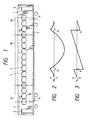
- reference numeral 1 denotes a car body
- reference numeral 2 denotes a side construction constituting both side surfaces of the car body 1.
- the side construction 2 is formed with openings 3 near its both longitudinal ends. Between the openings 3 are arranged several windows 5 partitioned by many intermediate posts 4.
- Reference numeral 6 denotes an underframe constituting a bottom surface of the car body 1.
- the car body 1 is supported by the truck through body bolsters arranged near longitudinal ends of the underframe 6.
- the body bolsters are arranged at positions indicated at A in Fig. 1.
- the body bolsters are used for transmitting a vertical load of the car body 1 to the truck and further transmitting either a drawing force or a braking action generated in the truck to the car body 1.
- a distribution of a bending moment M and a shearing load F in the car body are shown in Figs. 2 and 3.
- the car body 1 is constructed as follows. That is, the shearing stiffness is made larger at a part 1a near the body bolster in the longitudinal direction of the car body 1 than that of the central portion 1b and the bending stiffness is made larger at the central portion 1b than that near a part 1a of the body bolster.
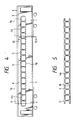
- FIG. 4 to 15 illustrates a practical structure for improving a shearing stiffness of the portion 1a near the body bolster illustrated in Fig. 1, and these structures will be described in detail.
- Reference numeral 7 denotes a wainscot portion constituting a lower part of the windows 5.
- Reference numeral 8 denotes a window head portion constituting an upper part of the windows 5.
- the wainscot portion 7 and the window head portion 8 are formed of aluminum alloy members.
- Reference numeral 4a denotes intermediate post frames for use in partitioning the windows 5 into several units. The intermediate post frames 4a are vertically arranged so as to connect the wainscot portion 7 with the window head portion 8. In this structure, side columns or posts arranged vertically from the window head portion 8 to the wainscot portion 7 are not arranged.
- Reference numeral 9 denotes an upper frame to be fixed to the lower edge portion of the window head portion 8.
- Reference numeral 10 denotes a lower frame to be fixed to an upper edge portion of the wainscot portion 7.
- the upper frame 9 and the lower frame 10 are connected through the intermediate post frames 4a so as to form a ladder-type intermediate post member 11.
- the intermediate post member 11 is made by high strength material, a stainless steel, for example.
- Reference numeral 12 denotes a belt rail arranged at an upper edge part of the wainscot portion 7, and reference numeral 13 denotes a window header arranged at the lower edge of the above-mentioned window head portion 8.
- the intermediate post member 11 is fixed by a method wherein the upper frame 9 is fixed to the window header 13 through blind rivets 14 and the lower frame 10 is fixed to the belt rail 12 through blind rivets 14.
- the blind rivets 14 are mounted in a longitudinal direction of the car body under an appropriate pitch.
- the blind rivets 14 may be used together with bonding material and further in place of the blind rivets, bolts and nuts may be used.
- the upper frame and the lower frame can be made of clad steel in which the same type of material as that of wainscot portion 7 and the window head portion 8, i.e. aluminum material and the same type of material as that of the intermediate post frames 4a, i.e. stainless steel are connected by an explosion press fitting process or the like.
- the upper frame and the lower frame are constructed by clad steel
- the upper frame and the window header as well as the lower frame and the belt rail can be connected by a welding operation. So, a fixing operation of the intermediate post frame to the side construction can easily be performed.
- the intermediate post member 11 may support the vertical load together with the car body 1.
- a shearing load may act at the intermediate post frames 4a of the intermediate post member 11 of the part 1a near the body bolster.
- the intermediate post frames 4a shows a secondary bending load is generated by the above-shearing load. Accordingly, if the intermediate post member 11 is made by a sufficient higher rigidity construction, it is possible to reduce any deformation generated under an action of the shearing load and the bending load against the car body 1.
- the lower frame 10 and the upper frame 9 of the intermediate post member 11 are directly connected to the belt rail 12 and the window header 13 of the side construction 2, and all these members integrally accept the vertical load and the like.
- the portion 1a near the body bolster of the side construction 2 shows an improved rigidity against the shearing force.
- the intermediate post frames 4a are formed of stainless steel, so its allowable stress is increased more than that of other portions. As the allowable stress of the intermediate post frames 4a is increased, a reliability of strength of the car body 1 can be improved.
- a rate of increasing of the rigidity per unit weight of the car body 1 is increased, so that its light weight can be attained.
- a feature of the structure of the present preferred embodiment consists in the fact that an entire length of the intermediate post member in the first preferred embodiment is shortened more than that of the first preferred embodiment.
- Reference numeral 11a denotes intermediate post members to be mounted at the side construction 2 corresponding to the portion 1a near the body bolsters of the side construction 2.
- the intermediate post frame members 11a have a short length in a longitudinal direction of the car body.
- the intermediate post frames 4 other than that where the intermediate post members 11a are mounted are constructed in the same manner as that of the prior art car body.
- the side posts are arranged in a vertical direction from the window head portion 8 to the wainscot portion 7 and the side posts constitute the intermediate post frames 4.
- the intermediate post members 11a are fixed to the window head portions and the wainscot portion of the side construction 2 with the blind rivets in the same manner as that of the first preferred embodiment.
- the portion 1a near the body bolster shows the similar situation as that of the first preferred embodiment.
- the central part 1b of the car body 1 is made of the same aluminum alloy as that of the other portions, its deformation is easily generated as compared with the portion 1a near the body bolster.
- the shearing load is low as shown in Fig. 3, and no problem may occur even if the stiffness of the intermediate post frames 4 is low.
- an arrangement in which the intermediate post members 11a are arranged at the portion 1a near the body bolster enables shearing stiffness of the portion 1a near the body bolster to be improved.
- the intermediate post members 11a are made shorter than that of the previous preferred embodiment, thereby a light weight of the entire car body 1 can be attained.
- a third preferred embodiment of the present invention will be described.
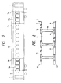
- a plurality of intermediate post frames are made by a single unit in place of the intermediate post members of the first and second preferred embodiments.
- Reference numeral 4b denotes intermediate post frames made of high rigidity material, a stainless steel, for example, and fixed in an interval coinciding with a width of each of the windows 5.
- the intermediate post frames 4b are formed in I-shape and its upper and lower ends are fixed to the belt rail 12 and the window header 13 with blind rivets 14.
- the intermediate post frames 4b are fixed to the side construction 2, thereby a rigidity of the side construction 2 can be improved.
- an improved rigidity of the side construction 2 enables a rigidity of the car body 1 to be improved.
- the intermediate post frames 4b are made by a single unit, its mass production can be performed. So, a productivity can be improved.
- the intermediate post frames 4b are at their upper and lower ends connected to the window head portion 8 and the wainscot portion 7. Accordingly, it is not necessary to use the upper frame 9 and the lower frame 10 as disclosed in the first and second preferred embodiments. With this arrangement, a light weight of the entire car body 1 can be attained.
- Each of the preferred embodiments shown in Figs. 9 to 12 is an example in which a shape of the opening of the window is improved.
- Reference numeral 5a denotes windows in which a vertical size of an opening portion is made shorter than that of the window 5b at the central part 1b of the side construction 2.
- the windows 5a are formed near the portion 1a of the body bolster.
- each of a vertical size Ha of the wainscot portion 7 and a vertical size ha of the window head portion 8 is made shorter than a vertical size of each of the wainscot portion 7 and the window head portion 8 at the central part 1b.
- the car body is effective in reducing a weight of the car body.
- a feature of constitution of the preferred embodiment of the present invention consists in the fact that all the sizes of the vertical portions of the windows are the same and that a width of the intermediate post and window is different to each other.
- Reference numeral 4c denotes an intermediate post frame at the portion la near the body bolster.
- the intermediate post frames 4c are formed such that its horizontal size, i.e. a width Ba is wider than a width Bb of the intermediate post frames 4d at the central part 1b of the car body.
- a difference of a width size between the intermediate post frame 4c and the intermediate post frame 4d is equal to a difference in width size between the window 5c and the window 5d. Accordingly, the window 5c is made shorter than a width size by a difference between the intermediate post frame 4c and the intermediate post frame 4c than that of the window 5d.
- the intermediate post frame 4c can reduce a bending deformation at a secondary location generated by a shearing deformation.
- the structure of the preferred embodiment of the present invention can improve a rigidity of the car body 1 and further provide a light weight of the car body 1. This is effective in view of the reduction of labor and manufacturing time in case of making the car body 1.
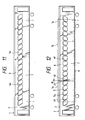
- FIG. 11 A feature of the structure of the preferred embodiment of the present invention consists in the fact that an intermediate post frame is formed to be inclined.
- Reference numeral 4e denotes an intermediate post frame for forming a window 5e.
- the intermediate post frames 4e are formed to be inclined by a certain degree in respect to a vertical axis.
- the side posts mounted in a vertical direction through the window head portion 8 and the wainscot portion 7 at their inside part are vertically arranged in an extended direction of the intermediate post frames 4e or from either an upper end or lower end of each of the intermediate post frames 4e.
- the intermediate post frames 4e are mounted to be inclined, so that the longitudinal direction of the intermediate post frames 4e in respect to the directions of the shearing deformation of the side construction 2 are crossed to each other or made in parallel to each other, or the longitudinal directions of the intermediate post frames 4e in respect to the direction of the shearing deformation of the side construction 2 are crossed to each other and are made similar to a parallel condition. Accordingly, they support a shearing force acting against the side construction 2 as an axial force of the intermediate post frames 4c. Due to this fact, the deformation in respect to the shearing load of the intermediate post frames 4e is reduced. In this way, the installation to be inclined of the intermediate post frames 4e enables a rigidity of the side construction 2 or the entire car body 1 to be improved.
- a feature of the structure of the present preferred embodiment consists in the fact that the intermediate post frames are mounted to be inclined and at the same time an inclining direction of each of the intermediate post frames are made opposite to each other in one car body.
- Reference numeral 4f denotes intermediate post frames each of which is inclined at its upper end toward the end of the car.
- An inclination angle ⁇ of the intermediate post frames 4f shows a higher value at the portion 1a of near the body bolster than that of the central portion 1b of the car body 1.
- An inclination angle ⁇ of the intermediate post frames 4f is gradually increased from the longitudinal central part of the car body 1 to the end of the car body.
- the inclination angle of the intermediate post frames 4f approaches mostly toward a direction of the shearing deformation at the portion 1a near the body bolster.
- the shearing load becomes a tensile axial force in the intermediate post frames 4f
- the buckling strength can be improved.
- the central portion 1b of the car body 1 shows a low inclination angle of the intermediate post frames 4f
- the vertical load acting against the underframe 6 can be transmitted as an axial force in a tension direction from the wainscot portion 7 toward the window head portion 8. In this way, since the load acting against the intermediate post frames 4f can be transmitted as an axial force in a tension direction, this is quite effective in view of its structure.
- FIG. 13 A feature of the structure of the preferred embodiment of the present invention consists in the fact that an area of the outside plate portion is increased without changing an apparent shape of the side construction.
- Reference numeral 7a denotes a at the portion 1a near the body bolster.
- the wainscot portion 7a is constructed such that the outside plate and the upper or lower frame are projected more downwardly than the wainscot portion 7b of the central part 1b of the car body 1.
- the wainscot portion 7a has an enlarged area of the outside plate.
- a height size Ha of the wainscot portion 7a is longer than the height size Hb of the wainscot portion 7b.
- Reference numeral 8a denotes a window head portion at the portion 1a near the body bolster.
- the window head portion 8a is constructed such that the outside plate and the frames are projected more upwardly than the window head portion 8b of the central part 1b of the car body 1.
- the window head portion 8a is made such that its outside plate portion has an enlarged area. Accordingly, a height size ha of the window head portion 8a is longer than the height size hb of the window head portion 8b.
- an upper side of the side construction 2 is partially projected, the cover 2c is arranged at a concave part so as to make a straight apparent shape.
- the area of the outside plate portion of the side construction 2 at the portion 1a near the body bolster can be enlarged, so a rigidity at this portion can be improved and an amount of deformation caused by a shearing load can be reduced.
- a feature of the structure of the preferred embodiment of the present invention consists in the fact that a reinforcement member is mounted at an inner surface of the outside plate in respect to the portion near the body bolster of the side construction.
- reference numeral 7c denotes a wainscot portion of a portion 1a near the body bolster.
- a vertical rib 17 To an inner surface of the outside plate constituting the wainscot portion 7c is connected a vertical rib 17.
- a corrugated plate 16 formed with vertical grooves therein with an arc spot welding.
- Reference numeral 15 denotes a side post which is integral with the intermediate post frame 4.
- Reference numeral 8c denotes a window head portion of the portion 1a near the body bolster.
- the vertical rib 17 To the inner surface of the outside plate constituting the window head portion 8c is connected the vertical rib 17.
- a flat plate 18 with an arc spot welding process To the inner side of the vertical rib 17 is connected a flat plate 18 with an arc spot welding process.
- rigidity of the wainscot portion 7c and window head portion 8c is enforced by the vertical rib 17, corrugated plate 16 and flat plate 18.
- the reinforcement member of the above-mentioned corrugated plate 16 and the flat plate 18 is arranged only at the portion 1a near the body bolster, thereby a light weight of the car body 1 can be attained.
- an effective improvement of the strength of the car body 1 can be attained.
- the above-mentioned corrugated plate 16 may be of a flat plate and even a rod-like reinforcing member can accomplish the improvement of the strength of the unit.
- a rivet bonding having a blind rivets and bonding material may be utilized as its connecting method.
- each of them has been described as one in which the outside plate is of a uniform plate thickness. But this may be used as an outside plate having a thick plate at a portion near the body bolster and further the plate may be uniformly formed one or a combined one of different plate thicknesses. With these, a rigidity of the side construction can be improved.
Landscapes
- Engineering & Computer Science (AREA)
- Mechanical Engineering (AREA)
- Transportation (AREA)
- Life Sciences & Earth Sciences (AREA)
- Wood Science & Technology (AREA)
- Body Structure For Vehicles (AREA)
- Buildings Adapted To Withstand Abnormal External Influences (AREA)
- Rolling Contact Bearings (AREA)
- Laminated Bodies (AREA)
Applications Claiming Priority (2)
| Application Number | Priority Date | Filing Date | Title |
|---|---|---|---|
| JP143730/88 | 1988-06-13 | ||
| JP14373088 | 1988-06-13 |
Publications (2)
| Publication Number | Publication Date |
|---|---|
| EP0347132A2 true EP0347132A2 (de) | 1989-12-20 |
| EP0347132A3 EP0347132A3 (de) | 1991-02-27 |
Family
ID=15345673
Family Applications (1)
| Application Number | Title | Priority Date | Filing Date |
|---|---|---|---|
| EP19890305885 Ceased EP0347132A3 (de) | 1988-06-13 | 1989-06-12 | Wagenaufbau für Schienenfahrzeuge |
Country Status (4)
| Country | Link |
|---|---|
| US (1) | US4995321A (de) |
| EP (1) | EP0347132A3 (de) |
| JP (1) | JPH0741828B2 (de) |
| KR (1) | KR910000457A (de) |
Cited By (2)
| Publication number | Priority date | Publication date | Assignee | Title |
|---|---|---|---|---|
| WO1998039190A1 (de) * | 1997-03-05 | 1998-09-11 | Talbot Gmbh & Co. Kg | Rahmen zum befestigen von flächenelementen |
| WO2014023521A1 (de) * | 2012-08-09 | 2014-02-13 | Siemens Aktiengesellschaft | Fensterprofil für ein schienenfahrzeug |
Families Citing this family (10)
| Publication number | Priority date | Publication date | Assignee | Title |
|---|---|---|---|---|
| DK57797A (da) * | 1997-05-20 | 1998-10-26 | Daimlerchrysler Rail Systems D | Vognkasse |
| US6550397B2 (en) * | 2001-03-27 | 2003-04-22 | Hitachi, Ltd. | Car body |
| JP4947944B2 (ja) * | 2005-09-27 | 2012-06-06 | 東急車輛製造株式会社 | 鉄道車両の構体 |
| JP4662837B2 (ja) * | 2005-10-26 | 2011-03-30 | 東急車輛製造株式会社 | 連節型の鉄道車両の構体 |
| JP2008290477A (ja) * | 2007-05-22 | 2008-12-04 | Nippon Sharyo Seizo Kaisha Ltd | 鉄道車両 |
| JP4516992B2 (ja) * | 2008-07-02 | 2010-08-04 | 日本車輌製造株式会社 | 鉄道車両 |
| JP4594414B2 (ja) * | 2008-07-02 | 2010-12-08 | 日本車輌製造株式会社 | 鉄道車両 |
| JP5502628B2 (ja) * | 2010-07-12 | 2014-05-28 | 川崎重工業株式会社 | 鉄道車両の構体構造 |
| JP6063208B2 (ja) * | 2012-10-24 | 2017-01-18 | 川崎重工業株式会社 | 鉄道車両の側構体 |
| USD757605S1 (en) * | 2012-11-21 | 2016-05-31 | Central Japan Railway Company | Passenger carrying car |
Family Cites Families (12)
| Publication number | Priority date | Publication date | Assignee | Title |
|---|---|---|---|---|
| US2024342A (en) * | 1934-01-12 | 1935-12-17 | American Car & Foundry Co | Railway car construction |
| US2256493A (en) * | 1934-04-13 | 1941-09-23 | Budd Edward G Mfg Co | Rail car front end construction |
| US2244661A (en) * | 1938-06-03 | 1941-06-10 | Pullman Standard Car Mfg Co | Railway car |
| US2595212A (en) * | 1945-01-15 | 1952-04-29 | Budd Co | Vehicle body, especially for rail cars |
| US2504659A (en) * | 1945-03-31 | 1950-04-18 | Budd Co | Body side wall for vehicles, especially railway cars |
| US2619045A (en) * | 1948-07-14 | 1952-11-25 | Budd Co | Body for land vehicles, especially railway cars, and method of its assembly |
| US2646008A (en) * | 1949-05-27 | 1953-07-21 | Budd Co | Vertically extended dead light panel of passenger railway cars |
| FR1359529A (fr) * | 1962-06-02 | 1964-04-24 | Talbot Waggonfab | Caisse de véhicule fermée pour le transport sur route et sur rails des marchandises et des voyageurs |
| DE2707573A1 (de) * | 1977-02-22 | 1978-08-24 | Krupp Gmbh | Fachwerktraeger mit verbessertem kraftfluss |
| JPS5911061U (ja) * | 1982-07-14 | 1984-01-24 | 株式会社新潟鐵工所 | 鉄道車両の側構体構造 |
| JPH078646B2 (ja) * | 1985-04-12 | 1995-02-01 | 株式会社日立製作所 | 鉄道車両用車体構造 |
| JPH0441002Y2 (de) * | 1986-06-30 | 1992-09-25 |
-
1989
- 1989-06-12 EP EP19890305885 patent/EP0347132A3/de not_active Ceased
- 1989-06-12 JP JP1146828A patent/JPH0741828B2/ja not_active Expired - Lifetime
- 1989-06-13 KR KR1019890008101A patent/KR910000457A/ko not_active Withdrawn
- 1989-06-13 US US07/365,439 patent/US4995321A/en not_active Expired - Fee Related
Cited By (2)
| Publication number | Priority date | Publication date | Assignee | Title |
|---|---|---|---|---|
| WO1998039190A1 (de) * | 1997-03-05 | 1998-09-11 | Talbot Gmbh & Co. Kg | Rahmen zum befestigen von flächenelementen |
| WO2014023521A1 (de) * | 2012-08-09 | 2014-02-13 | Siemens Aktiengesellschaft | Fensterprofil für ein schienenfahrzeug |
Also Published As
| Publication number | Publication date |
|---|---|
| KR910000457A (ko) | 1991-01-29 |
| JPH0741828B2 (ja) | 1995-05-10 |
| US4995321A (en) | 1991-02-26 |
| JPH0295971A (ja) | 1990-04-06 |
| EP0347132A3 (de) | 1991-02-27 |
Similar Documents
| Publication | Publication Date | Title |
|---|---|---|
| US5577796A (en) | Structural beam and method of manufacture thereof | |
| US6082811A (en) | Reinforcement for vehicle hollow structural member, having decreasing-thickness end portions | |
| US4966082A (en) | Construction and a manufacturing method of underframe for a rolling stock | |
| US5398989A (en) | Central pillar for the bodywork of a passenger car | |
| EP1462344B1 (de) | Karosserie eines Kraftfahrzeugs mit einem senkrecht orientierten Bauteil | |
| US5560672A (en) | Energy absorbing beam | |
| US6409257B1 (en) | Vehicle side sill structure | |
| EP0347132A2 (de) | Wagenaufbau für Schienenfahrzeuge | |
| US4919473A (en) | Structural shape (beam) especially for ramming protection in side doors and walls of motor-vehicle bodies | |
| US5346276A (en) | Bearing structure for the bodywork of a passenger car | |
| EP0888953B1 (de) | Vorderwagenaufbau eines Kraftfahrzeuges | |
| US20080276831A1 (en) | Car body structure | |
| EP0345962A2 (de) | Kastenaufbau für Schienenfahrzeug und Bauweise dafür | |
| EP0823363B1 (de) | Karosserie-Tragstruktur für ein Fahrzeug | |
| JP2009502641A (ja) | ベース構造体を有する車体と、ベース構造体を補強するための少なくとも1つの補強部材とを有する自動車 | |
| US12491798B2 (en) | Vehicle-seat-supporting structure | |
| US11186317B2 (en) | Vehicle body structure | |
| JP3581258B2 (ja) | 鉄道車両用衝撃吸収台枠構造 | |
| CN214524079U (zh) | 顶盖总成及车辆 | |
| CN102958778B (zh) | 铁道车辆结构体的构造 | |
| JP2821163B2 (ja) | 鉄道車両の屋根構体 | |
| US6394000B1 (en) | Car body | |
| JP3528079B2 (ja) | 鉄道車両の構体構造 | |
| JPH11301476A (ja) | 鉄道車両用衝撃吸収台枠構造 | |
| US20050166538A1 (en) | Construction component with a longitudinally changing cross-section shape |
Legal Events
| Date | Code | Title | Description |
|---|---|---|---|
| PUAI | Public reference made under article 153(3) epc to a published international application that has entered the european phase |
Free format text: ORIGINAL CODE: 0009012 |
|
| AK | Designated contracting states |
Kind code of ref document: A2 Designated state(s): DE FR GB IT |
|
| PUAL | Search report despatched |
Free format text: ORIGINAL CODE: 0009013 |
|
| AK | Designated contracting states |
Kind code of ref document: A3 Designated state(s): DE FR GB IT |
|
| 17P | Request for examination filed |
Effective date: 19910612 |
|
| 17Q | First examination report despatched |
Effective date: 19921013 |
|
| STAA | Information on the status of an ep patent application or granted ep patent |
Free format text: STATUS: THE APPLICATION HAS BEEN REFUSED |
|
| 18R | Application refused |
Effective date: 19940328 |