EP0347324A1 - Transportanlage mit Trageschienen und Zugkabel mit asymmetrischer Ausweiche und Verfahren, um den kleinstmöglichen Abstand zwischen zwei vor der Kreuzung kollisionsgefährdeten Fahrzeugen einer Standseilbahn zu erhöhen - Google Patents
Transportanlage mit Trageschienen und Zugkabel mit asymmetrischer Ausweiche und Verfahren, um den kleinstmöglichen Abstand zwischen zwei vor der Kreuzung kollisionsgefährdeten Fahrzeugen einer Standseilbahn zu erhöhen Download PDFInfo
- Publication number
- EP0347324A1 EP0347324A1 EP89401683A EP89401683A EP0347324A1 EP 0347324 A1 EP0347324 A1 EP 0347324A1 EP 89401683 A EP89401683 A EP 89401683A EP 89401683 A EP89401683 A EP 89401683A EP 0347324 A1 EP0347324 A1 EP 0347324A1
- Authority
- EP
- European Patent Office
- Prior art keywords
- section
- vehicles
- upstream
- length
- downstream
- Prior art date
- Legal status (The legal status is an assumption and is not a legal conclusion. Google has not performed a legal analysis and makes no representation as to the accuracy of the status listed.)
- Ceased
Links
- 238000009434 installation Methods 0.000 title claims abstract description 53
- 238000000034 method Methods 0.000 title claims description 10
- 238000011144 upstream manufacturing Methods 0.000 claims abstract description 70
- 230000001174 ascending effect Effects 0.000 claims description 18
- 230000007423 decrease Effects 0.000 claims description 3
- 210000000056 organ Anatomy 0.000 description 6
- 238000001514 detection method Methods 0.000 description 3
- 230000003247 decreasing effect Effects 0.000 description 2
- 238000006073 displacement reaction Methods 0.000 description 2
- 230000000694 effects Effects 0.000 description 2
Images

Classifications
-
- B—PERFORMING OPERATIONS; TRANSPORTING
- B61—RAILWAYS
- B61B—RAILWAY SYSTEMS; EQUIPMENT THEREFOR NOT OTHERWISE PROVIDED FOR
- B61B9/00—Tramway or funicular systems with rigid track and cable traction
Definitions
- the invention relates to an installation for transporting people or goods comprising two vehicles or trainsets of vehicles traveling back and forth in reverse directions on rails carrying rails between an upstream end station and a downstream end station. , at least one tractor cable forming a loop with two strands moving in opposite directions between the two stations, each vehicle being towed respectively by one of the two strands of this same tractor cable, the carrying tracks defining an upstream section to a single track s extending downstream from the upstream station, a downstream section with a single track extending upstream from the downstream station, and a two-way avoidance section located between the two upstream sections and downstream single track, the two vehicles crossing halfway between the end stations on the avoidance section.
- the avoidance section In such installations, it is desirable for the avoidance section to have the shortest possible length in order to limit the cost price as much as possible. This imperative takes on increased importance in the case of underground funiculars extending in an excavated tunnel, and in the case of modern funiculars in which vehicle speeds reach significant values, in particular greater than 10 m / s.
- the minimum length of the avoidance section is imposed by the safety distance required for detecting slack in the towing cable. and for the automatic braking of the descending vehicle when the ascending vehicle is in the critical position for disengaging the downstream section and enters the avoidance section.
- the descending vehicle is at a sufficient distance to allow it to stop by automatic braking before to collide with the ascending vehicle.
- the avoidance section being placed symmetrically with respect to the crossing point of the vehicles in the installations of the prior art (French patents 2,557,054 or 2,460,821), the descending vehicle is at the upstream entry of the section d avoidance when the ascending vehicle is at the downstream entry of the avoidance section in the critical release position.
- the length of the avoidance section is therefore dimensioned as a function of the critical distance available for the automatic braking of the descending vehicle.
- the safety distance required for braking the descending vehicle depends largely on the cruising speed of the vehicles and increases with this speed. Since this safety distance must necessarily be less than the critical distance available, it is necessary, in the installations of the prior art, either to reduce the speed of the vehicles, or to excessively increase the length of the avoidance section.
- the object of the invention is therefore to reduce the length of the avoidance section compared to the installations of the prior art without reducing the critical distance available for stopping the descending vehicle by automatic braking, that is to say the minimum distance available to avoid a collision with the ascending vehicle in the event of a cable break or its connection to the descending vehicle.
- the object of the invention is also to allow this critical distance to be increased on an existing installation without modifying the length of the avoidance section, and this at a lower cost, and thus thus to make it possible to increase the safety distance necessary for braking. automatic including cable slack detection and therefore vehicle speed.
- the invention provides an installation as mentioned above, characterized in that the length of the upstream section is greater than the length of the downstream section so that the vehicles intersect halfway between the stations on a part upstream of the avoidance section.
- the avoidance section extends from the vehicle crossing point over a greater distance downstream than upstream.
- the crossing point of the vehicles although located in the middle of the line, is not center of symmetry for the avoidance section, nor for the installation. The vehicle crossing point is not in the middle of the avoidance section.
- the invention also provides a method for increasing the minimum critical distance that can separate vehicles with risk of collision before vehicles cross over on the central avoidance section of a funicular installation built for which the two upstream and downstream sections have previously the same length, characterized in that the length of the upstream section is increased and / or that of the downstream section is decreased by a total distance less than the total length of the avoidance section, so that the vehicles do not cross more in the middle of the avoidance section, but on an upstream part of this section.
- the invention relates to a transport installation comprising two vehicles 1 or trainsets of vehicles traveling in opposite directions on load-bearing tracks 2 with rails or the like between two end stations 3, one of which 3a is situated at an altitude lower than l other 3b.
- the carrier tracks 2 are therefore inclined between the downstream end station 3a and the upstream end station 3b. While one 1 ′ of vehicles or trainsets goes down, the other 1 ⁇ goes up.
- the installation also includes at least one towing cable 4 forming a loop with two strands 4 ′, 4 ⁇ moving in opposite directions between the two stations 3a, 3b and associated respectively with each vehicle 1 ′, 1 ⁇ so that each vehicle 1 ′, 1 ⁇ is respectively towed by a strand 4 ′, 4 ⁇ of the same cable 4.
- the cable 4 passes, at least into the upstream station 3b around at least one pulley 5b driving and / or tension.
- the cable 4 forms an endless closed loop between the two stations 3 and passes in each station 3a, 3b on a deflection pulley 5a, 5b of which at least one is driven and connected to a device. motor not shown.
- At least one of the two pulleys 5a, 5b is a tension pulley mounted on a mobile carriage connected to a tensioning device. It is however possible in a known variant to provide only a half-loop in the upper part passing over a deflection pulley upstream motor 5b.
- upstream designates the organs or parts of the installation located at a higher altitude.
- index b designates these organs or parts.
- downstream designates the organs or parts situated at a lower altitude and the index a designates these organs or parts.
- the carrier tracks 2 define an upstream section 2b to a single track extending downstream from the upstream station 3b, a downstream section 2a to a single track extending upstream from the downstream station 3a , and an avoidance section 2c with two lanes 2′c, 2 ⁇ c, located between the two upstream sections 2b and downstream 2a and on which the two vehicles 1 ′, 1 ⁇ intersect.
- Each vehicle 1 ′ or 1 ⁇ travels as well on the climb as on the descent on the same lane 2′c or 2 ⁇ c of the avoidance section 2c.
- the two avoidance tracks 2′c and 2 ⁇ c are similar and symmetrical to each other with respect to the longitudinal median axis of the avoidance section 2c.
- the avoidance section 2c is also symmetrical with respect to a transverse plane 8 passing through the middle of this section 2c and comprises an upstream part 7b and a downstream part 7a which are symmetrical with respect to this plane 8 .
- the avoidance section 2c has a straight portion 9 and two connecting sections 10a, 10b.
- the crossing point 6 is located on the straight portion 9.
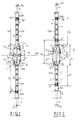
- FIG. 1 represents an installation according to the prior art in which the length la of the downstream section 2a is equal to that lb of the upstream section 2b, so that the avoidance section 2c is strictly centered on the crossing point 6.
- the entire installation, including the avoidance section 2c, is therefore symmetrical with respect to the crossing point 6.
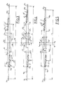
- the vehicles 1 are represented in three distinct positions: a position D ′, D ⁇ at the start of a station, a position E ′, E ⁇ at the start of tracks 2′c, 2 ⁇ c of avoidance section 2c, and a crossing position C ′, C ⁇ on the avoidance section 2c.
- position E ′, E ⁇ vehicles 1 are in the so-called critical position for which the distance between them with risk of collision is the smallest.
- the risk of collision exists but the distance separating the vehicles 1 ′, 1 ⁇ is greater.
- E ′, E ⁇ the risk of collision no longer exists until the vehicles 1 ′, 1 ⁇ leave the avoidance section 2c via symmetrical positions of the positions E ′, E ⁇ .
- safety distance the distance downstream necessary for the detection of the rupture of the cable 4 or of its connection and for the automatic braking of the descending vehicle 1 ′, hereinafter referred to as "safety distance” is less in all cases at the minimum distance dc which can separate the vehicles 1 with risk of collision before crossing, hereinafter referred to as "critical distance”.
- the critical distance dc is determined when the ascending vehicle 1 ⁇ is in position E ⁇ , the most downstream position for which it is just engaged on the avoidance section 2c and can no longer collide, given the spacing lateral x minimum imposed, with a descending vehicle 1 ′ if the latter were to cross the ascending vehicle 1 ⁇ due to an incident such as a break in the cable 4 or its attachment to the vehicle.
- the critical distance dc is that separating the vehicles 1 ′, 1 ⁇ when the ascending vehicle 1 ⁇ is in the entry E ⁇ position on the avoidance section 2c. More specifically, the critical distance dc is that separating the two downstream ends 11a ′, 11a ⁇ of vehicles 1 ′, 1 ⁇ which could collide. However, this critical distance dc is found between the two centers 12 ′, 12 ⁇ of the vehicles 1 ′, 1 ⁇ (FIG. 3). If the critical distance dc is greater than the safety distance, it is clear that no collision is possible before the crossing as long as the automatic braking of the vehicles is active. After the crossing, no collision will be possible either since the highest vehicle will be ascending.
- the entry E ⁇ position on the avoidance section 2c of the ascending vehicle 1 ⁇ is always its critical position.
- the entry position E ′ on the avoidance section 2c is also the critical position of the descending vehicle 1 ′. Indeed, when the ascending vehicle 1 ⁇ is in position E ⁇ , the descending vehicle 1 ′ is in position E ′.
- the critical distance dc corresponds to the engagement length le.
- the critical distance dc is less than the length lc of the avoidance section 2c.
- the length lb of the upstream section 2b is greater than the length la of the downstream section 2a so that the vehicles 1 ′, 1 ⁇ intersect at 6 on an upstream part 7b of the section avoidance 2c.
- the middle 8 of the avoidance section 2c is located downstream at a distance L from the crossing point 6 of the vehicles, that is to say at a distance L from the middle 6 of the installation. The avoidance section 2c therefore extends from the crossing point 6 of the vehicles 1 over a greater distance downstream than upstream.
- the descending vehicle 1 ′ When the ascending vehicle 1 ⁇ enters the track 2 ⁇ c of the avoidance section 2c and is in critical position E ⁇ , the descending vehicle 1 ′ is not yet in the entry position E ′ symmetrical with the position E ⁇ of the ascending vehicle 1 ⁇ , but is in a position more upstream F ′ on the upstream section 2b or slightly engaged on the avoidance section 2c.
- the critical distance dc is then the distance separating the descending vehicle 1 ′ in position F ′ from the ascending vehicle 1 ⁇ in position E ⁇ .
- the minimum critical distance dc which can separate the vehicles 1 with risk of collision before crossing is greater than the engagement length le of the avoidance section 2c, but is less than or equal to twice this length on.
- the critical distance dc is equal to twice the length of engagement le, crossing takes place as far upstream as possible as shown in FIG. 6.
- the critical distance dc and therefore the safety distance required for braking vehicles 1 can be greater in an installation according to the invention.
- the engagement length le and therefore the length lc of the avoidance section 2c can be shorter in an installation according to the invention.
- the avoidance section 2c is arranged asymmetrically with respect to the crossing point 6 of the vehicles 1.
- the crossing point 6 is located between the middle 8 of the avoidance section 2c and the position input E ′ extreme of the descending vehicle 1 ′ for which a collision-free crossing is possible taking into account the minimum lateral deviation x imposed ( Figure 6).
- the difference in length lb-la between the upstream section 2b and the downstream section 2a is such that the crossing of the vehicles 1 takes place as far upstream as possible on the avoidance section 2c, taking into account on the one hand the minimum lateral deviation x imposed by safety standards (Figure 6) between vehicles 1 at crossing 6, and on the other hand possibly - in particular in the case of a downstream driving pulley 5a and a driving pulley upstream deflection 5b of tension - of the extension of the tractor cable 4 by creep between two adjustments of the position of vehicles 1 on the cable 4.
- the most extreme upstream position possible for the crossing point 6 is shown in Figure 6.
- this extreme position of the crossing point 6 shown in FIG. 6 is not used in practice because it is too close to the point of collision.
- a safety factor and possible length variations of the tractor cable 4 must be taken into account (creep, thermal expansion, etc.). Consequently, according to the invention, the difference lb-la is less than the engagement length le which is equal to twice the distance between the center 12 ⁇ of the ascending vehicle 1 ⁇ in the entry position E ⁇ most downstream allowing collisionless crossing taking into account the minimum lateral deviation x and the middle 8 of the avoidance section 2c.
- the difference in length lb-la between the two upstream sections 2b and downstream 2a is of the order of lr-lv where lr is the length of the straight portion 9 of the avoidance section 2c and lv the length of the vehicles 1.
- the upstream end 11b ′, 11b ⁇ of the vehicles 1 ′, 1 ⁇ coincides with the upstream end of the straight portion 9.
- the length lc of the avoidance section 2c and therefore that lr of its straight portion 9 are dimensioned taking into account the characteristics of the connecting sections 10a, 10b so that the safety distance required for the collisionless braking of the descending vehicle 1 ′ is less than the critical distance dc, in particular is less than twice the length of engagement of the avoidance section 2c, taking into account the usual safety factor and possible lengthening of the cable 4 by creep.
- the vehicles 1 can be associated with the tractor cable 4 by disengageable means or of the "policeman's hat” type so that these vehicles 1 can be moved along this cable 4, in particular when the characteristics of this cable 4 are modified, by example in length under the effect of creep. It is possible to associate the vehicles 1 with the cable 4 in a fixed, non-removable manner, for example by caps. In this case the cable 4 is regularly shortened to take account of the creep elongations. However, between two successive adjustments of the length of the cable 4 or of the respective positions of the vehicles 1 relative to the cable 4, the cable 4 lengthens in the direction of the tension pulley 5. Therefore, the crossing point 6 is therefore also moved towards the tensioning pulley 5. This possible displacement must be taken into account when dimensioning the avoidance section 2c.
- the extension of the cable 4 lowers the crossing point 6 and thus decreases the critical distance dc . Otherwise, the crossing point 6 rises during the elongation of the cable 4 which increases the critical distance dc but may pose problems of interference from vehicles 1 at the crossing if the portion of engagement length located there above the initial crossing point 6 is not sufficient.
- the difference in length lb-la between the two upstream sections 2b and downstream 2a is less than the length of engagement of the avoidance section 2c with a value of the order of or greater than the upstream displacement of the crossing point 6 under the effect of the elongation of the cable 4 between two successive adjustments of the length of the cable 4 or of the position of the vehicles 1 relative to the cable 4.
- the invention also relates to a method for increasing the critical distance.
- minimum dc that can separate vehicles 1 with risk of collision before vehicles 1 cross over on the straight portion 9 of the central avoidance section 2c of a funicular installation built for which the two upstream sections 2b and downstream 2a have a single track previously the same length, characterized in that the length of the upstream section 2b is increased and / or that of the downstream section 2a is decreased by a total distance 2L less than the total length lc of the avoidance section 2c, in particular less than the engagement length 1c of this avoidance section 2c, so that the vehicles 1 no longer intersect in the middle 8 of the avoidance section 2c but on an upstream part 7b of this section 2c.
- the distance 2L is of the order of lr-lv where lr is the length of the rectilinear portion 9 of the avoidance section 2c and lv is the length of the vehicles 1.
- the downstream station 3a and the starting position D ⁇ of the vehicles 1 have been reassembled in this station 3a over a distance 2L, thus reducing the length of the downstream section 2a by this same length 2L.
- the method according to the invention is particularly advantageous because it is easier to move the starting position D ′, D ⁇ of a vehicle in a boarding / disembarking station 3 than to modify the geometrical characteristics of the 2c or line avoidance.
- a funicular installation had a central avoidance section 2c arranged symmetrically with a total length lc of 150m, the length lr of its rectilinear portion being 44m.
- the length of each train of vehicles 1 was 30 m, the width of the vehicles was 2.2 m and the two tracks 2′c, 2 ⁇ c of the avoidance section were spaced 2.7 m apart (center distance).
- the radii of curvature of the connecting sections 10a, 10b were 500 m.
- the minimum critical distance dc that can separate vehicles 1 with risk of collision before crossing was 45 m for a safety distance necessary for detecting slack in the cable 4 and stopping the descending vehicle by automatic braking of 39.5 m, the speed of vehicle cruising being 10m / s.
- the starting position of the vehicles 1 at the downstream station 3a has been raised by 15 m, so that the vehicles 1 intersect 7.5 m from the middle 8 of the avoidance section 2c.
- the critical distance dc then increased to 60 m, and the speed of vehicles 1 could be increased up to 12 m / s for a safety distance of 50.5 m.
Landscapes
- Engineering & Computer Science (AREA)
- Transportation (AREA)
- Mechanical Engineering (AREA)
- Train Traffic Observation, Control, And Security (AREA)
- Control Of Position, Course, Altitude, Or Attitude Of Moving Bodies (AREA)
- Operating, Guiding And Securing Of Roll- Type Closing Members (AREA)
- Sealing Devices (AREA)
Applications Claiming Priority (2)
| Application Number | Priority Date | Filing Date | Title |
|---|---|---|---|
| FR8808170A FR2632915B1 (fr) | 1988-06-17 | 1988-06-17 | Installation de transport a voies porteuses a rails et a cable tracteur dont l'evitement est asymetrique et procede pour augmenter la distance critique d'un funiculaire |
| FR8808170 | 1988-06-17 |
Publications (1)
| Publication Number | Publication Date |
|---|---|
| EP0347324A1 true EP0347324A1 (de) | 1989-12-20 |
Family
ID=9367435
Family Applications (1)
| Application Number | Title | Priority Date | Filing Date |
|---|---|---|---|
| EP89401683A Ceased EP0347324A1 (de) | 1988-06-17 | 1989-06-15 | Transportanlage mit Trageschienen und Zugkabel mit asymmetrischer Ausweiche und Verfahren, um den kleinstmöglichen Abstand zwischen zwei vor der Kreuzung kollisionsgefährdeten Fahrzeugen einer Standseilbahn zu erhöhen |
Country Status (4)
| Country | Link |
|---|---|
| EP (1) | EP0347324A1 (de) |
| JP (1) | JPH0295969A (de) |
| FR (1) | FR2632915B1 (de) |
| NO (1) | NO892523L (de) |
Cited By (6)
| Publication number | Priority date | Publication date | Assignee | Title |
|---|---|---|---|---|
| US5611282A (en) * | 1995-09-05 | 1997-03-18 | Alt; John D. | Method and apparatus for operating multiple passenger carrying trams simultaneously in both directions in a single dedicated lane transit system |
| US5676059A (en) * | 1995-09-05 | 1997-10-14 | Alt; John Darby | Tram coordinating method and apparatus |
| EP1193153A1 (de) * | 2000-10-02 | 2002-04-03 | Poma Otis Systemes de Transport, (Société par actions simplifiée) | Anlage zum Bewegen von kabelgezogenen Fahrzeugen |
| EP1176077A3 (de) * | 2000-07-24 | 2002-10-16 | Innova Patent GmbH | Anlage zur Beförderung von Personen |
| FR2943025A1 (fr) * | 2009-03-16 | 2010-09-17 | Pomagalski Sa | Installation de transport a vehicule guide le long d'une unique voie de circulation |
| US20180009448A1 (en) * | 2016-07-11 | 2018-01-11 | Poma | Installation and method of transport by ground cable |
Families Citing this family (2)
| Publication number | Priority date | Publication date | Assignee | Title |
|---|---|---|---|---|
| JP4763505B2 (ja) * | 2006-04-14 | 2011-08-31 | 日本ケーブル株式会社 | 索道装置 |
| CN112660208B (zh) * | 2020-12-24 | 2022-12-20 | 交控科技股份有限公司 | 基于电子地图数据的系统关键参数生成方法及装置 |
Citations (3)
| Publication number | Priority date | Publication date | Assignee | Title |
|---|---|---|---|---|
| FR941934A (fr) * | 1947-02-18 | 1949-01-25 | Cie D Entpr S Electro Mecaniqu | Système de translation de voie d'évitement |
| FR2460821A1 (fr) * | 1979-07-12 | 1981-01-30 | Voest Alpine Ag | Funiculaire |
| FR2557054A1 (fr) * | 1983-12-22 | 1985-06-28 | Skirail Ind | Dispositif de roulement et de guidage d'un funiculaire sur des rails |
-
1988
- 1988-06-17 FR FR8808170A patent/FR2632915B1/fr not_active Expired - Lifetime
-
1989
- 1989-06-15 EP EP89401683A patent/EP0347324A1/de not_active Ceased
- 1989-06-16 NO NO89892523A patent/NO892523L/no unknown
- 1989-06-17 JP JP1153596A patent/JPH0295969A/ja active Pending
Patent Citations (3)
| Publication number | Priority date | Publication date | Assignee | Title |
|---|---|---|---|---|
| FR941934A (fr) * | 1947-02-18 | 1949-01-25 | Cie D Entpr S Electro Mecaniqu | Système de translation de voie d'évitement |
| FR2460821A1 (fr) * | 1979-07-12 | 1981-01-30 | Voest Alpine Ag | Funiculaire |
| FR2557054A1 (fr) * | 1983-12-22 | 1985-06-28 | Skirail Ind | Dispositif de roulement et de guidage d'un funiculaire sur des rails |
Cited By (12)
| Publication number | Priority date | Publication date | Assignee | Title |
|---|---|---|---|---|
| US5611282A (en) * | 1995-09-05 | 1997-03-18 | Alt; John D. | Method and apparatus for operating multiple passenger carrying trams simultaneously in both directions in a single dedicated lane transit system |
| US5676059A (en) * | 1995-09-05 | 1997-10-14 | Alt; John Darby | Tram coordinating method and apparatus |
| EP1176077A3 (de) * | 2000-07-24 | 2002-10-16 | Innova Patent GmbH | Anlage zur Beförderung von Personen |
| EP1193153A1 (de) * | 2000-10-02 | 2002-04-03 | Poma Otis Systemes de Transport, (Société par actions simplifiée) | Anlage zum Bewegen von kabelgezogenen Fahrzeugen |
| FR2814713A1 (fr) * | 2000-10-02 | 2002-04-05 | Poma Otis Systemes De Transp | Installation de deplacement de vehicules tractes par cable |
| FR2943025A1 (fr) * | 2009-03-16 | 2010-09-17 | Pomagalski Sa | Installation de transport a vehicule guide le long d'une unique voie de circulation |
| WO2010106236A1 (fr) * | 2009-03-16 | 2010-09-23 | Pomagalski | Installation de transport a vehicule guide le long d'une unique voie de circulation |
| CN102427985A (zh) * | 2009-03-16 | 2012-04-25 | 波马加尔斯基公司 | 具有沿单个行车道被引导的车辆的交通设备 |
| US8770112B2 (en) | 2009-03-16 | 2014-07-08 | Pomagalski | Transport equipment with a vehicle guided along a single traffic lane |
| US20180009448A1 (en) * | 2016-07-11 | 2018-01-11 | Poma | Installation and method of transport by ground cable |
| FR3053651A1 (fr) * | 2016-07-11 | 2018-01-12 | Poma | Installation et procede de transport par cable terrestre |
| EP3269611A1 (de) * | 2016-07-11 | 2018-01-17 | Poma | Anlage und verfahren zum transport über erdkabel |
Also Published As
| Publication number | Publication date |
|---|---|
| FR2632915A1 (fr) | 1989-12-22 |
| NO892523D0 (no) | 1989-06-16 |
| JPH0295969A (ja) | 1990-04-06 |
| NO892523L (no) | 1989-12-18 |
| FR2632915B1 (fr) | 1990-10-19 |
Similar Documents
| Publication | Publication Date | Title |
|---|---|---|
| EP0491632B1 (de) | Kuppelbare Seilbahn oder kuppelbarer Sessellift mit zwei Kabelschleifen | |
| EP0114129B1 (de) | Vorrichtung zum Regulieren des Abstands von schaltbaren Seilbahnkabinen oder Sesselliften | |
| EP0245163B1 (de) | Auskuppelbare Kabine oder auskuppelbarer Sitz für Kabelbahnen | |
| EP0814992B1 (de) | Seilbahn mit zwei einstiegsstellen | |
| EP3359437B1 (de) | Kabelbeförderungseinrichtung | |
| EP0263035B1 (de) | Schwebebahntransportsystem mit zwei Trage- und Zugkabeln, sowie versetzten Endstationsscheibenrädern | |
| EP1864882B1 (de) | Seilgezogene Transportanlage mit Zusammenstellung der Fahrzeuge vor dem Ein-/Ausstieg und deren Steuerungsverfahren | |
| EP0282418B1 (de) | Seilbahn mit zwei Trag- und Zugseilen sowie zwei vertikal versetzten Umlaufrädern | |
| EP0611220B1 (de) | Transportanlage auf einem Bahnkörper mit mehreren Gleisabschnitten | |
| FR2632915A1 (fr) | Installation de transport a voies porteuses a rails et a cable tracteur dont l'evitement est asymetrique et procede pour augmenter la distance critique d'un funiculaire | |
| EP2990292B1 (de) | Anlage und verfahren zum transport über seilbahn | |
| EP2623388B1 (de) | Station für Sessellift mit hohem Durchsatz und geringem Platzbedarf | |
| EP1193153B1 (de) | Anlage zum Bewegen von kabelgezogenen Fahrzeugen | |
| EP3383718B1 (de) | Flurfreie fördereinrichtung | |
| EP0399919B1 (de) | Abkuppelbare Drahtseilbahn | |
| EP4208380A1 (de) | Transporteinrichtung | |
| FR2933359A1 (fr) | Installation de transport a deux boucles de cable raccordees dans un local intermediaire | |
| FR2731196A1 (fr) | Teleporteur a deux emplacements d'embarquement | |
| FR2774963A1 (fr) | Installation de transport a cable aerien a defilement continu a boucle | |
| CA2036405A1 (fr) | Quai d'embarquement pour systemes de transport semi-continus | |
| EP0700816B1 (de) | Förderanlage mit zwei Schienen | |
| CH689115A5 (fr) | Installation de transport aérien par câbles. | |
| EP0933277A1 (de) | Antriebsmechanismus eines Transportsystems mit Kabeln, der ein Antriebsrad mit doppelter Umschlingung aufweist | |
| FR2985486A1 (fr) | Telepherique doublement pulse | |
| FR2638693A1 (fr) | Telepherique debrayable |
Legal Events
| Date | Code | Title | Description |
|---|---|---|---|
| PUAI | Public reference made under article 153(3) epc to a published international application that has entered the european phase |
Free format text: ORIGINAL CODE: 0009012 |
|
| AK | Designated contracting states |
Kind code of ref document: A1 Designated state(s): CH FR IT LI SE |
|
| 17P | Request for examination filed |
Effective date: 19891026 |
|
| 17Q | First examination report despatched |
Effective date: 19901113 |
|
| STAA | Information on the status of an ep patent application or granted ep patent |
Free format text: STATUS: THE APPLICATION HAS BEEN REFUSED |
|
| 18R | Application refused |
Effective date: 19910829 |