EP0814992B1 - Seilbahn mit zwei einstiegsstellen - Google Patents
Seilbahn mit zwei einstiegsstellen Download PDFInfo
- Publication number
- EP0814992B1 EP0814992B1 EP96908154A EP96908154A EP0814992B1 EP 0814992 B1 EP0814992 B1 EP 0814992B1 EP 96908154 A EP96908154 A EP 96908154A EP 96908154 A EP96908154 A EP 96908154A EP 0814992 B1 EP0814992 B1 EP 0814992B1
- Authority
- EP
- European Patent Office
- Prior art keywords
- chairs
- pickup
- track
- chair
- skiers
- Prior art date
- Legal status (The legal status is an assumption and is not a legal conclusion. Google has not performed a legal analysis and makes no representation as to the accuracy of the status listed.)
- Expired - Lifetime
Links
- 230000001360 synchronised effect Effects 0.000 claims description 3
- 230000033764 rhythmic process Effects 0.000 claims 3
- 230000001133 acceleration Effects 0.000 description 5
- 238000009434 installation Methods 0.000 description 3
- 238000013459 approach Methods 0.000 description 1
- 239000000969 carrier Substances 0.000 description 1
- 238000006073 displacement reaction Methods 0.000 description 1
- 230000000750 progressive effect Effects 0.000 description 1
- 238000011144 upstream manufacturing Methods 0.000 description 1
Images





Classifications
-
- B—PERFORMING OPERATIONS; TRANSPORTING
- B61—RAILWAYS
- B61B—RAILWAY SYSTEMS; EQUIPMENT THEREFOR NOT OTHERWISE PROVIDED FOR
- B61B12/00—Component parts, details or accessories not provided for in groups B61B7/00 - B61B11/00
- B61B12/02—Suspension of the load; Guiding means, e.g. wheels; Attaching traction cables
- B61B12/022—Vehicle receiving and dispatching devices
-
- B—PERFORMING OPERATIONS; TRANSPORTING
- B61—RAILWAYS
- B61B—RAILWAY SYSTEMS; EQUIPMENT THEREFOR NOT OTHERWISE PROVIDED FOR
- B61B1/00—General arrangement of stations, platforms, or sidings; Railway networks; Rail vehicle marshalling systems
- B61B1/02—General arrangement of stations and platforms including protection devices for the passengers
Definitions
- the invention relates to a detachable chairlift according to the preamble of claim 1.
- the invention is described below in its application preferable to a detachable chairlift, and more particularly at a boarding station usually located downstream, but it is clear that it is applicable to other carriers, including cable cars.
- Transport capacity is a key factor in chairlift and it depends on the number of seats in each seat and seat speed and line spacing.
- the development of detachable chairlifts has enabled increase in line speed and therefore speed, while with easy boarding on scrolling seats at reduced speed.
- the speed of seats in stations being weaker, these are closer together than on the line, especially in the boarding area and at high speed the passage of skiers between the two seats close together, to accessing the boarding location is all the more difficult as the size of the seats, two, three, four or more places, is great.
- the present invention aims to allow the realization a chairlift with high transport capacity and boarding safely and this goal is achieved by implementing of the features of claim 1.
- Document US-A-4,050,385 describes a detachable chairlift, of which the seat transfer path is split in two parallel lanes, each with a boarding location.
- the seats are oriented alternately on one and on the other way, in order to increase the flow of the installation.
- the two lanes intersect and the boarding locations are arranged on the outer sections of the tracks.
- Skiers are sit perpendicular to the line and they get on the seats, stationary, rear, without crossing path seats or one of the tracks. Boarding at a reduced stop the speed of the chairlift and, at the crossing of the two tracks, one seats are loaded and the slightest adjustment can cause body accident.
- the document EP-A- 0 306 771 describes a siding of a detachable chairlift, on which the seats are stored short distance from each other.
- the grouping by pairs of seats increases the interval between the rear seat of a pair and the front seat of the next pair.
- This grouping can be controlled by a cadence changer, located at the entrance to the station, to change the deceleration speed of the seats after uncoupling the cable.
- the Cadence Changer can also be placed in the upper station, so that group the seats in pairs as soon as you leave this station, the unequal distribution of seats along the line not being not embarrassing, since these seats are empty.
- the transfer trajectory is split by a bifurcation in an inner and an outer track, each having a boarding location with an access runway.
- a switching device alternately orients the seats on both lanes and the frequency of the seats at a boarding location is thus halved, by to facilitate boarding. It is also conceivable provide three or more channels to reduce again this frequency.
- Access to the boarding location from the outside way poses no difficulty.
- the way interior is however surrounded by the exterior route and the access track to the boarding location interior must cross a path.
- the risk of collision between a seat and a skier, advancing on the access road, is thus significantly reduced and almost equivalent to that of chairlifts conventional, since the two seats of a pair cross at the same time crossing.
- the runway crossing area of access and tracks advantageously coincides with the area of bifurcation of the tracks.
- the locations boarding lanes are arranged so that the access routes to these locations are tangent to a curve of the track and the inner track, in the form of a half-loop, extends in the axis of the line, in the usual way.
- the boarding location of the inner lane is adjacent to the crossing area of the access track and tracks.
- a gate, placed on the access track, advantageously controls the engagement of skiers on this access track.
- the two tracks are, in the crossing zone, both curved towards the boarding location and the seat in front, seen in the direction of travel, in the pair of seats is oriented in the bifurcation on the inner track
- This curve of the tracks allows rapid clearance of the crossing by the seats.
- the forward seat follows the most curved trajectory and so he approaches a skier in delay from behind, without great risk of accident.
- the internal route and the outer track are arranged in the axis of the line, being offset along this axis.
- the front seat is preferably oriented in the bifurcation on the outside track. This seat in front crosses the access track perpendicularly, while the back seat oblique on the inside track in quickly clearing the crossing area.
- Track lengths and seat travel speeds on these tracks are such that the seats have the same cadence as at the end of the tracks the entry, with a possible shift of the order of seats.
- the boarding station can easily be arranged for a landing of skiers, by planning on each lane, before the embarkation location, a landing location.
- the two boarding spaces are arranged one after the other on the same track.
- the seats are grouped in pairs one first time for the passage from the first location boarding and a second time for the passage of the second boarding location, with seat swapping grouped together, so that the seat, which was in front of the pair at the entrance to the first boarding location and which has onboard skiers at this first location, is at the back of the pair at the entrance to the second boarding location.
- Boarding locations are arranged in a curve of the track, so that the access tracks to these locations are tangent to the curve and these two locations boarding passes are substantially at right angles. Gates, synchronized with the scrolling of the seats, control the commitment of the SUT skiers to the access tracks.
- a simplified version, according to the invention has a transfer path split into two lanes parallel, each of which has a location of landing in the form of a ramp.
- a referral device alternately orient the seats on one and on the other track and the two ramps are sloping to allow the clearance for skiers normally passing under the seats and the way. Any risk of collision with a seat is therefore excluded.
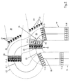
- a chairlift boarding station disengageable includes at the entrance of the station a zone 10 of declutching the seats 11 of a cable 12 and decelerating them seats, which roll on a rail 13 to be transferred towards the exit of the station where they are re-accelerated on a acceleration zone 14 before being re-coupled to the opposite strand of the cable 12.
- the driving and deceleration of the seats 11 uncoupled from the cable 12 is produced by any suitable means, for example by cleats or sets of wheels has pneumatic 33.
- Such detachable chairlifts, on board at low speed are well known and need not be describe in more detail.
- a switch 15, disposed after the area of deceleration 10, allows to selectively orient the seats 11 on an inner track 16 or on an outer track 17.
- the two channels 16,17 are connected by a switch 18 to the area acceleration 14 and the outer track 17 surrounds the track interior 16.
- the transfer trajectory of the seats 11, from a strand of cable 12 to the opposite strand, is thus split by the two tracks 16,17, which each have a rail 13 and associated means of propulsion.
- Inner track 16 is in shape of half-loop, arranged in the axis of the line of the usual way. It has a curved part 20 on which is provided with a boarding location 22, with a access track 23, the axis of which is substantially tangent to the curve 20.
- Seats 11 have six seats, but this number can be different and the access track 23, with six gates 24, allows a front displacement of six skiers 21, represented in the figures by triangles, towards the location boarding area 22.
- the external route 17 is a half-loop distorted with a lateral offset, so as to follow at the start the curvature of the interior track 16 and present a first part 19 curved in the same direction as the track interior 16 towards boarding location 22.
- This first part 19 is followed by a curved part 27 having, substantially in the middle, a boarding location 29, with an access track 30, the axis of which is tangent to the curve 27.
- the access track 30, with six gates 24, allows movement of six skiers 21 from the front to boarding location 29.
- the two access tracks 23 and 30 are parallel and side by side coast, runway 30 of external route 17 directly accessing at the loading location, in the usual way by rear, while runway 23 of interior track 16 crosses the outer lane 17, the crossing zone 25 coinciding with the switch point bifurcation zone 15.
- the boarding location 22 of the inner lane 16 is adjacent to the crossing zone 25 and the gates 24 are arranged just before this crossing zone 25. We limit thus the maximum distance to be crossed by skiers 21 between the gates 24 and the boarding location 22.
- the same gates 24 command crossing the crossing 25 and access to the boarding location 22.
- the gates 24 are arranged obliquely on the track to marry near the curvature of the tracks 16,17 and their opening can be progressive, as the seat passes 11.
- the deceleration device 33 for seats 11 is arranged for decadent the seats 11 and bring them together two by two, to form pairs of close seats, which cross together the crossing zone 25.
- the approximation can be achieved either by stopping a seat 11 at the entrance to the crossing 25 to wait for the next seat, either preferably by modulating the decelerations, so that the two seats 11 are presented together at the entrance to the crossing 25 and cross it at the same time.
- the spacing between the pairs of seats 11 is increased and that skiers can pass more easily between the pairs of seats to access the site boarding 22.
- the decentering is carried out in the upstream station, the seats voids are already grouped in pairs on the line, so to simplify the downstream boarding station.
- the length of the outer track 17 is greater than that of the inner track 16 and if the tracks 16,17 are crossed at the same speed by the seats 11, the difference in length must be determined so as to find at the exit the regular cadence, with a shift in the order of the seats, the interior track seat 16 short passing one or two seats on the outer track 17 long. Cadence can also be restored by different seat speeds 11 on tracks 16,17 or in acceleration zone 14.
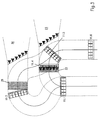
- FIG. 2 The operation of the installation is shown in Figures 2 to 5.
- a pair of seats 11.4 and 11.5, were slowed down and brought closer to zone 10 of deceleration, so as to cross at slow speed and together the crossing and bifurcation zone 25.
- the first seat 11.4 has just crossed the switch 15, which oriented it on the interior route 16 towards the boarding location 22.
- the second seat 11.5 of the pair enters the area of crossing 25 and will be oriented on the outside track 17.
- the access track 23 is closed by the gates 24, which prevent skiers 21 from entering the crossing zone 25 and access boarding location 22 of the lane interior 16.
- the previous seat 11.3 is on the curved part 20 of the outer lane 17, at embarkation location 29, while the previous seat 11.2, which followed the path inner 16 short, is engaged on the acceleration zone 14 and passed the first seat 11.1, which traveled the way long 17.
- seat 11.6, which follows the pair of seats 11.4,11.5, is notably spaced from this pair.
- the seat 11.4 is at boarding location 22 and seat 11.5 commits to the outer track 17.
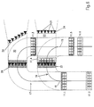
- the following figures 4 and 5 illustrate the progression of the various seats 11, which are oriented alternately on the inner track 16 and the outer track 17 by switch 15, as well as the opening of the gates 24. There is no need to describe this operation in more detail.
- FIG. 6 illustrates another arrangement of the channels 16, 17, in which the outer track 17 is a half-loop, also arranged in the axis and in the extension of the line, being offset from the track half-loop interior 16.
- Access track 23 of interior route 16 is then substantially perpendicular to the external track 17.
- the seat 11.5, which will be oriented on the track exterior 17 is at the front in the pair of seats 11.5,11.6 and the rear seat 11.6 quickly clears the area of crossing by forking to the side on the inner track 16.
- the operation is of course identical to that described above with reference to Figures 2 to 5.
- each channel 16,17 can include a landing location, arranged before the location boarding 22,29, these spaces not being obligatorily in the curves 20.27.
- the arrival station can be substantially identical to the departure station with split tracks. Depending on the flow and the structure of the installation a standard station with a single way may be sufficient, since the landing is more easy than boarding.
- Figure 7 illustrates a simplified disembarkation, in which the seats are alternately steered on two adjacent parallel tracks 32.34, each having a sloping landing ramp 35.36, which puts skiers under seats 11 and lanes 32,34, as indicated by arrows in the figure, without risk of collision.
- the boarding station has a single track 13, in the form of a half-loop extending the line of the usual way.
- Two boarding spaces 37.39, with their access tracks 38.40, are arranged in the curve of the track, respectively in the middle and at the exit of the curved, so that all of the seats 11 pass successively at the two boarding locations 37.39.
- the two locations 37.39 are substantially perpendicular one relative to each other and the access roads 38.40, tangent to the curve, are fitted with gates 24, the opening of which is synchronized with the scrolling of seats 11.
- the seats 11 are presented at the entrance to the curve, grouped in pairs and they are moved together towards the first boarding location 37, where the seat in before the pair picks the skiers 21.
- the grouping of 11 seats in pairs must be changed so that the seat in rear of pair at first boarding location 37 present forward at the second location 39 to embark the skiers.
- This permutation is obtained by slowing down and / or acceleration of successive seats so as to regroup the seat still empty with the seat, which follows it and separate it from the seat which preceded it.
- skiers 21 have more time to advance on the access tracks 38.40 and stand at boarding locations 37.39.
- Figures 8 and 9 represent the position of seats 11 at two times successive.
- a pair of seats 11.4,11.5 arrive at the entrance to the curve, ready to cross the track access 38 and board the front seat 11.4 skiers waiting at the first boarding location 37.
- the figure 9 represents this moment when the pair of seats 11.4,11.5 crossed the first location 37 and caught the seat previous 11.3, which advances, grouped with seat 11.4, to the second location 39 by crossing the access track 40.
Landscapes
- Engineering & Computer Science (AREA)
- Transportation (AREA)
- Mechanical Engineering (AREA)
- Escalators And Moving Walkways (AREA)
- Seats For Vehicles (AREA)
- Electric Propulsion And Braking For Vehicles (AREA)
- Footwear And Its Accessory, Manufacturing Method And Apparatuses (AREA)
Claims (10)
- Entkuppelbarer Sessellift, mit einem ununterbrochen laufenden Luftseil (12), das sich zwischen zwei Stationen erstreckt, in denen es auf Umführungsrollen läuft, um eine endlose Schleife zu bilden, und mit Sesseln (11), die an das Seil auf der Strecke gekuppelt sind, und die in den Stationen von dem Seil entkuppelt werden, um auf einer Strecke umzulaufen zum Überleiten der Sessel von einem Schleifen-Seilstrang auf den anderen, wobei sie an wenigstens zwei Einsteigstellen (22, 29; 37, 39) vorbeifahren, wo die Skiläufer (21) abwechselnd in die aufeinanderfolgenden Sessel (11) einsteigen, dadurch gekennzeichnet, dass die Skiläufer zu einer Einsteigstelle Zugang haben, wenn sie zwischen den Sesseln durchgehen, und dass zwei aufeinanderfolgende, vom Seil (12) entkuppelte Sessel (11) zu einem Sesselpaar gruppiert sind, im Durchgang zu der genannten Einsteigstelle, wobei der Zwischenraum zwischen den beiden gruppierten Sesseln verkleinert ist und der Zwischenraum zwischen dem Sesselpaar und dem nachfolgenden oder vorangehenden Sessel entsprechend vergrössert ist, um den Zugang der Skiläufer zu der Einsteigstelle zu erleichtern.
- Sessellift gemäss Anspruch 1, dadurch gekennzeichnet, dass ein Taktwechsler (33) der Sessel (11) die Fortbewegungsgeschwindigkeit der Sessel verändert, um letztere paarweise zu gruppieren.
- Sessellift gemäss Anspruch 1 oder 2, dadurch gekennzeichnet, dass der Taktwechsler (33) die Verlangsamungsgeschwindigkeit der Sessel (11) nach ihrer Abkupplung vom Seil (12) verändert, um zwei aufeinanderfolgende Sessel aneinander zu nähern und paarweise zu gruppieren.
- Sessellift gemäss Anspruch 1 oder 2, dadurch gekennzeichnet, dass der Taktwechsler der Sessel (11) in der oberen Station angeordnet ist, um die Sessel unmittelbar nach dem Ausgang der oberen Station paarweise zu gruppieren.
- Sessellift gemäss irgendeinem der vorhergehenden Ansprüche, dadurch gekennzeichnet, dass die Überleitungsstrecke durch eine Abzweigung in eine innere Bahn (16) und eine äussere Bahn (17) verdoppelt wird, von denen jede eine Einsteigstelle (22, 29) mit einer Zugangsspur (23, 30) aufweist, dass eine Weichenstellvorrichtung (15) die Lasten (11) abwechselnd auf die eine und die andere Bahn (16, 17) schickt, und dass die Sessel paarweise in dem Kreuzungsbereich (25) der Sesselstrecke und der Zugangsspur (23) an der Einsteigstelle (22) der inneren Bahn (16) gruppiert sind, um den Zwischenraum zwischen den Sesselpaaren zu vergrössern und den Durchgang der Skiläufer zwischen den Sesselpaaren zu der Einsteigstelle der inneren Bahn zu erleichtern.
- Sessellift gemäss Anspruch 5, dadurch gekennzeichnet, dass der Abzweigungsbereich (15) der beiden Bahnen (16, 17) annähernd mit dem genannten Kreuzungsbereich (25) übereinstimmt.
- Sessellift gemäss irgendeinem der Ansprüche 1 bis 4, dadurch gekennzeichnet, dass die beiden Einsteigstellen (37, 39) eine hinter der anderen auf der selben Bahn angeordnet sind, dass die Sessel (11) ein erstes Mal paarweise gruppiert werden für den Durchgang zu der ersten Einsteigstelle (37) und ein zweites Mal für den Durchgang zu der zweiten Einsteigstelle (39), mit einer Vertauschung der gruppierten Sessel, so dass der Sessel, der sich an der ersten Einsteigstelle (37) hinter einem Paar befand, sich an der zweiten Einsteigstelle (39) vor einem Paar befindet.
- Sessellift, gemäss einem der vorhergehenden Ansprüche, mit Zugangsspuren (23, 30; 38, 40) für die Skiläufer (21) zu den Einsteigstellen (22, 29; 37, 39), dadurch gekennzeichnet, dass die Einsteigstellen (22, 29; 37, 39) in einer Kurve (23, 30) der Bahn angeordnet sind, so dass die Zugangsspuren zu diesen Stellen eine Tangente zu der Kurve (20, 27) der Bahn (13; 16, 17) bilden.
- Sessellift gemäss irgendeinem der vorhergehenden Ansprüche, mit Zugangsspuren (23, 30; 38, 40) für die Skiläufer zu den Einsteigstellen (22, 29; 37, 39), dadurch gekennzeichnet, dass eine Pforte (24),, die mit dem Vorbeifahren der Sessel (11) synchronisiert ist, auf den Zugangsspuren zu den Einsteigstellen angeordnet ist.
- Sessellift gemäss irgendeinem der vorhergehenden Ansprüche, mit einer Aussteigstation, dadurch gekennzeichnet, dass die Überleitungsstrecke in zwei parallele Bahnen (32, 34) unterteilt ist, von denen jede eine Aussteigstelle (35, 36) aufweist, dass eine Weichenstellvorrichtung (15) die Sessel (11) abwechselnd auf die eine und die andere Bahn schickt, und dass die beiden Aussteigstellen abfallend sind, um die Befreiung der Skiläufer zu ermöglichen, ohne eine Bahn zu kreuzen.
Applications Claiming Priority (3)
| Application Number | Priority Date | Filing Date | Title |
|---|---|---|---|
| FR9503568A FR2731972B1 (fr) | 1995-03-22 | 1995-03-22 | Teleporteur ayant deux emplacements d'embarquement |
| FR9503568 | 1995-03-22 | ||
| PCT/FR1996/000413 WO1996029223A1 (fr) | 1995-03-22 | 1996-03-20 | Teleporteur ayant deux emplacements d'embarquement |
Publications (2)
| Publication Number | Publication Date |
|---|---|
| EP0814992A1 EP0814992A1 (de) | 1998-01-07 |
| EP0814992B1 true EP0814992B1 (de) | 1999-01-20 |
Family
ID=9477449
Family Applications (1)
| Application Number | Title | Priority Date | Filing Date |
|---|---|---|---|
| EP96908154A Expired - Lifetime EP0814992B1 (de) | 1995-03-22 | 1996-03-20 | Seilbahn mit zwei einstiegsstellen |
Country Status (7)
| Country | Link |
|---|---|
| US (1) | US5873310A (de) |
| EP (1) | EP0814992B1 (de) |
| JP (1) | JPH11502170A (de) |
| AT (1) | ATE175933T1 (de) |
| CA (1) | CA2214460A1 (de) |
| FR (1) | FR2731972B1 (de) |
| WO (1) | WO1996029223A1 (de) |
Cited By (2)
| Publication number | Priority date | Publication date | Assignee | Title |
|---|---|---|---|---|
| EP1972520A1 (de) | 2007-03-22 | 2008-09-24 | Innova Patent GmbH | Verfahren zum Betrieb einer Seilbahnanlage mit einer Talstation und mit mindestens einer Bergstation und Seilbahnanlage |
| CN103442962A (zh) * | 2011-01-31 | 2013-12-11 | 波马加尔斯基公司 | 车辆分组缆线运输系统和用于控制该系统的方法 |
Families Citing this family (20)
| Publication number | Priority date | Publication date | Assignee | Title |
|---|---|---|---|---|
| FR2769564B1 (fr) * | 1997-10-09 | 2000-01-07 | Pomagalski Sa | Estacade pour station d'embarquement de telesiege |
| FR2774963B1 (fr) | 1998-02-17 | 2000-04-14 | Pomagalski Sa | Installation de transport a cable aerien a defilement continu a boucle |
| ES2196590T3 (es) * | 1998-07-01 | 2003-12-16 | Doppelmayr France S A S | Telesilla con embarque mejorado. |
| AT409253B (de) * | 2000-07-20 | 2002-07-25 | Innova Patent Gmbh | Anlage zur beförderung von personen und verfahren zum betrieb einer derartigen anlage |
| FR2882321B1 (fr) * | 2005-02-22 | 2007-05-04 | Pomagalski Sa | Station d'embarquement a haut debit pour un teleporteur de transport par un cable aerien |
| US20070034105A1 (en) * | 2005-08-09 | 2007-02-15 | Jean-Francois Mugnier | Aerial ropeway transport methods |
| JP2007055288A (ja) * | 2005-08-22 | 2007-03-08 | Nippon Cable Co Ltd | 自動循環式索道における搬器の一時停止運行方法 |
| AT503502A3 (de) * | 2006-03-23 | 2010-07-15 | Innova Patent Gmbh | Verfahren zum betrieb einer seilbahnanlage und seilbahnanlage |
| FR2899191B1 (fr) * | 2006-04-04 | 2008-05-30 | Denis Creissels Consultant Sar | Installation de telecabines automatiques |
| FR2899549B1 (fr) * | 2006-04-10 | 2008-06-27 | Pomagalski Sa | Installation de transport a cable aerien vehiculant des sieges et des cabines |
| AT503615A3 (de) * | 2006-04-26 | 2010-06-15 | Innova Patent Gmbh | Seilbahnanlage mit an ein trag- und förderseil ankuppelbaren fahrbetriebsmitteln |
| KR101463250B1 (ko) * | 2008-05-26 | 2014-11-18 | 주식회사 포스코 | 자동운전차량시스템에서의 차량의 군집주행방법 |
| ATE488412T1 (de) * | 2008-08-21 | 2010-12-15 | Innova Patent Gmbh | Seilbahnanlage |
| FR2986486B1 (fr) * | 2012-02-06 | 2015-05-29 | Pomagalski Sa | Gare pour telesiege a haut debit |
| AT515098B1 (de) * | 2013-11-28 | 2015-06-15 | Innova Patent Gmbh | Anlage zur Beförderung von Personen |
| EP3293069A1 (de) * | 2016-09-09 | 2018-03-14 | Bartholet Maschinenbau AG | Verfahren sowie seilbahnanlage zur beförderung von personen |
| IT201700036544A1 (it) * | 2017-04-03 | 2018-10-03 | Leitner Spa | Stazione per un impianto di trasporto a fune, impianto di trasporto a fune comprendente tale stazione e metodo di funzionamento di tale impianto di trasporto a fune |
| GB2595666B (en) * | 2020-06-01 | 2022-10-05 | Fraser Monteiro Andre | Ropeway Transport System |
| US12145631B2 (en) * | 2021-02-25 | 2024-11-19 | Disney Enterprises, Inc. | Station with infinite ingress and egress times for use in transportation systems |
| FR3148976A1 (fr) | 2023-05-23 | 2024-11-29 | Bureau Des Etudes De Cables | Installation autonome de transport de véhicules par un câble à mouvement continu |
Family Cites Families (12)
| Publication number | Priority date | Publication date | Assignee | Title |
|---|---|---|---|---|
| FR1436695A (fr) * | 1965-03-15 | 1966-04-29 | Dispositif permettant à des voyageurs ou des marchandises d'accéder à des véhicules détachables individuellement d'un système d'entraînement à marche continue | |
| CH443390A (fr) * | 1965-10-29 | 1967-09-15 | Battelle Development Corp | Complexe de transport continu sans fin pour voyageurs à destinations multiples |
| US3548753A (en) * | 1968-06-18 | 1970-12-22 | Edward M Thurston | Loading means for chair lift |
| AT405271B (de) * | 1995-04-07 | 1999-06-25 | Doppelmayr & Sohn | Seilbahnanlage mit einem um zwei umlenkscheiben geführten trag- und förderseil für fahrbetriebsmittel |
| US3987734A (en) * | 1975-02-05 | 1976-10-26 | Horn Clifford V | Modular rapid transportation system for passengers and freight |
| US4050385A (en) * | 1975-09-29 | 1977-09-27 | Walt Disney Productions | High capacity passenger transport apparatus |
| FR2476579A1 (fr) * | 1980-02-25 | 1981-08-28 | Pomagalski Sa | Dispositif d'embarquement d'une installation de transport a cable aerien, notamment d'un telesiege debrayable |
| FR2528781B1 (fr) * | 1982-06-18 | 1985-10-18 | Gimar Sa | Teleporte a transit rapide |
| FR2598373B1 (fr) * | 1986-05-06 | 1988-09-02 | Pomagalski Sa | Amenagement de voie de transfert et/ou de garage pour une telecabine ou un telesiege debrayable |
| DE3872630D1 (de) * | 1987-09-09 | 1992-08-13 | Von Roll Transportsysteme | Gleiseinrichtung fuer die fahrzeuge einer foerderanlage, insbesondere umlauf-seilfoerderanlage. |
| FR2670451A1 (fr) * | 1990-12-18 | 1992-06-19 | Pomagalski Sa | Telecabine ou telesiege debrayage a deux boucles de cable. |
| FR2678571B1 (fr) * | 1991-07-02 | 1993-10-29 | Pomagalski Sa | Dispositif d'automatisation de l'acces d'un teleporteur. |
-
1995
- 1995-03-22 FR FR9503568A patent/FR2731972B1/fr not_active Expired - Fee Related
-
1996
- 1996-03-20 CA CA002214460A patent/CA2214460A1/en not_active Abandoned
- 1996-03-20 AT AT96908154T patent/ATE175933T1/de not_active IP Right Cessation
- 1996-03-20 EP EP96908154A patent/EP0814992B1/de not_active Expired - Lifetime
- 1996-03-20 WO PCT/FR1996/000413 patent/WO1996029223A1/fr not_active Ceased
- 1996-03-20 US US08/894,947 patent/US5873310A/en not_active Expired - Fee Related
- 1996-03-20 JP JP8528134A patent/JPH11502170A/ja not_active Ceased
Cited By (3)
| Publication number | Priority date | Publication date | Assignee | Title |
|---|---|---|---|---|
| EP1972520A1 (de) | 2007-03-22 | 2008-09-24 | Innova Patent GmbH | Verfahren zum Betrieb einer Seilbahnanlage mit einer Talstation und mit mindestens einer Bergstation und Seilbahnanlage |
| CN103442962A (zh) * | 2011-01-31 | 2013-12-11 | 波马加尔斯基公司 | 车辆分组缆线运输系统和用于控制该系统的方法 |
| CN103442962B (zh) * | 2011-01-31 | 2016-03-30 | 波马加尔斯基公司 | 车辆分组缆线运输系统和用于控制该系统的方法 |
Also Published As
| Publication number | Publication date |
|---|---|
| EP0814992A1 (de) | 1998-01-07 |
| WO1996029223A1 (fr) | 1996-09-26 |
| JPH11502170A (ja) | 1999-02-23 |
| CA2214460A1 (en) | 1996-09-26 |
| US5873310A (en) | 1999-02-23 |
| ATE175933T1 (de) | 1999-02-15 |
| FR2731972A1 (fr) | 1996-09-27 |
| FR2731972B1 (fr) | 1997-06-20 |
Similar Documents
| Publication | Publication Date | Title |
|---|---|---|
| EP0814992A1 (de) | Seilbahn mit zwei einstiegsstellen | |
| EP0125967B1 (de) | Höhenverstellbare Endstation für Kabelbahnen | |
| EP0491632B1 (de) | Kuppelbare Seilbahn oder kuppelbarer Sessellift mit zwei Kabelschleifen | |
| EP2001721B1 (de) | Automatische seilbahnanlage | |
| EP0611220B1 (de) | Transportanlage auf einem Bahnkörper mit mehreren Gleisabschnitten | |
| EP1864882B1 (de) | Seilgezogene Transportanlage mit Zusammenstellung der Fahrzeuge vor dem Ein-/Ausstieg und deren Steuerungsverfahren | |
| EP0114129A1 (de) | Vorrichtung zum Regulieren des Abstands von schaltbaren Seilbahnkabinen oder Sesselliften | |
| EP2036797A1 (de) | Anlage zum Transport von Passagieren an Bord eines Fahrzeugs mit Hilfe von zwei Verschiebungselementen des Fahrzeugs | |
| EP3359437B1 (de) | Kabelbeförderungseinrichtung | |
| FR2927598A1 (fr) | Systeme d'aide a l'embarquement et/ou au debarquement de passagers a bord de cabines | |
| FR2598373A1 (fr) | Amenagement de voie de transfert et/ou de garage pour une telecabine ou un telesiege debrayable | |
| FR2568208A1 (fr) | Dispositif de propulsion dans les stations des cabines ou des sieges d'une telecabine ou d'un telesiege | |
| EP0034983B1 (de) | Ein- und Aussteigvorrichtung einer Seilbahntransporteinrichtung, insbesondere für einen entkuppelbaren Sessellift | |
| FR2715006A1 (fr) | Installation de transport à deux câbles aériens. | |
| FR1387152A (fr) | Transporteur continu à vitesse variable | |
| EP1193153B1 (de) | Anlage zum Bewegen von kabelgezogenen Fahrzeugen | |
| EP2670645B1 (de) | Seilbahntransportsystem für fahrzeuggruppen und steuerungsverfahren dafür | |
| FR2731196A1 (fr) | Teleporteur a deux emplacements d'embarquement | |
| EP1089904B1 (de) | Sessellift mit verbessertem einstieg | |
| FR2752803A1 (fr) | Procede d'augmentation du debit horaire de personnes empruntant des vehicules transportes par cable et installation pour sa mise en oeuvre | |
| FR2774963A1 (fr) | Installation de transport a cable aerien a defilement continu a boucle | |
| EP4208380A1 (de) | Transporteinrichtung | |
| FR2757816A1 (fr) | Station d'embarquement d'un telesiege debrayable a deux zones d'embarquement | |
| FR2854116A1 (fr) | Station d'embarquement pour un teleporteur de transport par cable aerien | |
| FR2639303A1 (fr) | Telepheriques debrayables a vehicules roulant au sol en stations |
Legal Events
| Date | Code | Title | Description |
|---|---|---|---|
| PUAI | Public reference made under article 153(3) epc to a published international application that has entered the european phase |
Free format text: ORIGINAL CODE: 0009012 |
|
| 17P | Request for examination filed |
Effective date: 19970923 |
|
| AK | Designated contracting states |
Kind code of ref document: A1 Designated state(s): AT CH FR IT LI |
|
| GRAG | Despatch of communication of intention to grant |
Free format text: ORIGINAL CODE: EPIDOS AGRA |
|
| GRAG | Despatch of communication of intention to grant |
Free format text: ORIGINAL CODE: EPIDOS AGRA |
|
| GRAH | Despatch of communication of intention to grant a patent |
Free format text: ORIGINAL CODE: EPIDOS IGRA |
|
| 17Q | First examination report despatched |
Effective date: 19980630 |
|
| GRAH | Despatch of communication of intention to grant a patent |
Free format text: ORIGINAL CODE: EPIDOS IGRA |
|
| GRAA | (expected) grant |
Free format text: ORIGINAL CODE: 0009210 |
|
| AK | Designated contracting states |
Kind code of ref document: B1 Designated state(s): AT CH FR IT LI |
|
| REF | Corresponds to: |
Ref document number: 175933 Country of ref document: AT Date of ref document: 19990215 Kind code of ref document: T |
|
| REG | Reference to a national code |
Ref country code: CH Ref legal event code: EP |
|
| ITF | It: translation for a ep patent filed | ||
| PLBE | No opposition filed within time limit |
Free format text: ORIGINAL CODE: 0009261 |
|
| STAA | Information on the status of an ep patent application or granted ep patent |
Free format text: STATUS: NO OPPOSITION FILED WITHIN TIME LIMIT |
|
| 26N | No opposition filed | ||
| PGFP | Annual fee paid to national office [announced via postgrant information from national office to epo] |
Ref country code: CH Payment date: 20030331 Year of fee payment: 8 |
|
| PG25 | Lapsed in a contracting state [announced via postgrant information from national office to epo] |
Ref country code: CH Free format text: LAPSE BECAUSE OF NON-PAYMENT OF DUE FEES Effective date: 20040331 Ref country code: LI Free format text: LAPSE BECAUSE OF NON-PAYMENT OF DUE FEES Effective date: 20040331 |
|
| REG | Reference to a national code |
Ref country code: CH Ref legal event code: PL |
|
| PGFP | Annual fee paid to national office [announced via postgrant information from national office to epo] |
Ref country code: AT Payment date: 20050311 Year of fee payment: 10 |
|
| PG25 | Lapsed in a contracting state [announced via postgrant information from national office to epo] |
Ref country code: IT Free format text: LAPSE BECAUSE OF NON-PAYMENT OF DUE FEES Effective date: 20050320 |
|
| PG25 | Lapsed in a contracting state [announced via postgrant information from national office to epo] |
Ref country code: AT Free format text: LAPSE BECAUSE OF NON-PAYMENT OF DUE FEES Effective date: 20060320 |
|
| PGFP | Annual fee paid to national office [announced via postgrant information from national office to epo] |
Ref country code: FR Payment date: 20080328 Year of fee payment: 13 |
|
| REG | Reference to a national code |
Ref country code: FR Ref legal event code: ST Effective date: 20091130 |
|
| PG25 | Lapsed in a contracting state [announced via postgrant information from national office to epo] |
Ref country code: FR Free format text: LAPSE BECAUSE OF NON-PAYMENT OF DUE FEES Effective date: 20091123 |