EP0347385A1 - Aneroid-Barometer-Mechanismus - Google Patents
Aneroid-Barometer-Mechanismus Download PDFInfo
- Publication number
- EP0347385A1 EP0347385A1 EP89810436A EP89810436A EP0347385A1 EP 0347385 A1 EP0347385 A1 EP 0347385A1 EP 89810436 A EP89810436 A EP 89810436A EP 89810436 A EP89810436 A EP 89810436A EP 0347385 A1 EP0347385 A1 EP 0347385A1
- Authority
- EP
- European Patent Office
- Prior art keywords
- lever
- support
- capsule
- primary lever
- fact
- Prior art date
- Legal status (The legal status is an assumption and is not a legal conclusion. Google has not performed a legal analysis and makes no representation as to the accuracy of the status listed.)
- Granted
Links
Images

Classifications
-
- G—PHYSICS
- G01—MEASURING; TESTING
- G01L—MEASURING FORCE, STRESS, TORQUE, WORK, MECHANICAL POWER, MECHANICAL EFFICIENCY, OR FLUID PRESSURE
- G01L7/00—Measuring the steady or quasi-steady pressure of a fluid or a fluent solid material by mechanical or fluid pressure-sensitive elements
- G01L7/02—Measuring the steady or quasi-steady pressure of a fluid or a fluent solid material by mechanical or fluid pressure-sensitive elements in the form of elastically-deformable gauges
- G01L7/10—Measuring the steady or quasi-steady pressure of a fluid or a fluent solid material by mechanical or fluid pressure-sensitive elements in the form of elastically-deformable gauges of the capsule type
- G01L7/12—Measuring the steady or quasi-steady pressure of a fluid or a fluent solid material by mechanical or fluid pressure-sensitive elements in the form of elastically-deformable gauges of the capsule type with exhausted chamber; Aneroid barometers
Definitions
- the invention relates to an aneroid barometer mechanism comprising a support, an aneroid capsule, a shaft carrying an indicator needle, means for transforming linear movements of deformation of the capsule into angular rotational movements of the indicator needle.
- the document EP 0 126 273 describes a barometer mechanism, characterized in that a helical-shaped element is fixedly mounted, in that the output shaft can not only rotate, but can also move in the axial direction, and in that the output shaft is supported by its end which faces the membrane capsule on said membrane capsule and is held in this position by the return spring.
- the linear movements of deformation of the capsule are of very small amplitude, of the order of two tenths of a mm.
- the object of the invention is to provide a mechanism capable of amplifying the deformation movements of the capsule and thus increasing the reading range of the barometer.
- the barometer mechanism comprises, placed in a support for a combined action, a primary lever, the center of which is in contact with the center of the capsule, which exerts a motive force Fm at this point of the lever, the axis of rotation of this primary lever being situated at the periphery of the support and held in place by a support spring, the capsule being fixed on the support by a concentric screw to a geometric axis XX passing through the center of the primary lever; - a worm screw provided with a helical ramp concentric with the axis XX, held by a bridge in the center of the primary lever of which this screw is thus made integral, freely rotating and surmounted, opposite the capsule, by the 'barometer indicator needle; a secondary lever, the axis of rotation of which rests on the free end of the primary lever, which exerts on the secondary lever a driving force Fm ′ transmitted to the worm screw by a point formed by the free end of said secondary lever, this point being permanently in the
- This mechanism has the advantage of amplifying the movements of the aneroid capsule transmitted to an indicator needle fixed on the worm.
- the barometer mechanism is placed in a housing 1 closed by a dial. It consists of a support 2 of two complementary levers, a primary lever 4 and a secondary lever 6, cooperating to transmit to a worm screw 5 carrying an indicator needle, the deformations of a circular aneroid capsule 3, fixed by a screw 30 in the center 20 of the support 2.
- the screw 30 makes it possible to adjust the barometer as a function of the altitude of its static location.
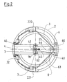
- the support 2 is circular and includes in particular: a threaded orifice 20 for the screw 30 of the capsule 3, a housing 21 receiving the axis of rotation 40 of the primary lever 4, - pins 22 serving as support, on either side of the primary lever, to the branches of a spring 8 (fig.2) which, after passing through baffles 220, 221, maintain the axis of rotation of the lever in its housing , - a notch 23, diametrically opposite to the housing 21, guides the oscillations of the primary lever 4, a guide 24, fixed to the bottom of the support 2 and perpendicular to its base, passes through an oblong opening 44 of the free arm 41 of the primary lever 4, the upper part 25 of this guide 24 emerging through the oblong opening 44 , serves as a fulcrum 63 for the secondary lever 6.
- the primary lever 4 comprises two equal arms, on either side of its fulcrum 43 on the center 31 of the capsule 3, one, fixed by the spring 8 in the housing 21, comprising at its end l axis of rotation 40, the other receiving on its free end 41, the axis of rotation 60 of the secondary lever 6, the point of contact 31/43 between the capsule and the primary lever is the point of application of a driving force Fm generated by the variations in volume of the capsule 3 under the effect of variations in atmospheric pressure.
- This force Fm is exerted along a geometric axis XX perpendicular to the plane of symmetry of the capsule 3, by pivoting the primary lever 4 around its axis of rotation 40.
- the primary lever 4 comprises, opposite the contact point 43 and concentric with the axis XX, a cage 42 receiving a worm screw 5.
- a peg 45 is fixed on the primary lever 4, between the cage 42 and the free end 41 to guide the free arm 61 of the secondary lever 6.
- the worm 5, placed in the cage 42 is made integral with the primary lever 4 by a bridge 7 fixed by two screws 70, which prohibits any axial movement by leaving free its angular rotation.
- the screw 5 has three concentric parts with the same axis XX perpendicular to the superimposed planes of the support 2, of the capsule 3 and of the primary lever 4: a cylinder 50 provided with a helical ramp 51, rotating on a pivot 52 and extended to the opposite the pivot by a shaft 53 carrying the indicator needle.
- a secondary lever 6 is supported by its axis of rotation 60 on the free end 41 of the primary lever 4.
- the tilting point 63 of the lever 6 is supported, through the oblong opening 44 on the upper part 25 of the guide 24.
- the arm 61 of the lever 6 has a free end in the shape of a point 62. This point 62 penetrates into the helical ramp 51 of the worm 5. The movements of the lever 6 cause the angular rotation of the worm 5 by the action of the tip 62 on the helical ramp 51.
- a spring 8 exerts a restoring force R which maintains permanent contact of the primary lever 4 on the capsule 3. It bears on the one hand on the support 2, at the calf level of the axis of rotation 40 of the lever 4 that it maintains in its housing 21 passing through the pins 22 and on baffles 220, 221 located on either side of the housing 21 at the periphery of the support 2, on the other hand on the secondary lever 6 at a point 64 located between the axis of rotation 60 and the tipping point 63.
- this barometer mechanism is composed of five elements cooperating with each other, a support 2, a primary lever 4, an endless screw 5 provided with a helical ramp 51, a secondary lever 6 whose book end is a point 62, a support spring 8.
Landscapes
- Physics & Mathematics (AREA)
- General Physics & Mathematics (AREA)
- Measuring Fluid Pressure (AREA)
- Dental Preparations (AREA)
- Adhesives Or Adhesive Processes (AREA)
- Diaphragms For Electromechanical Transducers (AREA)
Priority Applications (1)
| Application Number | Priority Date | Filing Date | Title |
|---|---|---|---|
| AT89810436T ATE80725T1 (de) | 1988-06-17 | 1989-06-08 | Aneroid-barometer-mechanismus. |
Applications Claiming Priority (2)
| Application Number | Priority Date | Filing Date | Title |
|---|---|---|---|
| FR8808407 | 1988-06-17 | ||
| FR8808407A FR2633043B1 (fr) | 1988-06-17 | 1988-06-17 | Mecanisme de barometre aneroide |
Publications (2)
| Publication Number | Publication Date |
|---|---|
| EP0347385A1 true EP0347385A1 (de) | 1989-12-20 |
| EP0347385B1 EP0347385B1 (de) | 1992-09-16 |
Family
ID=9367602
Family Applications (1)
| Application Number | Title | Priority Date | Filing Date |
|---|---|---|---|
| EP89810436A Expired - Lifetime EP0347385B1 (de) | 1988-06-17 | 1989-06-08 | Aneroid-Barometer-Mechanismus |
Country Status (5)
| Country | Link |
|---|---|
| US (1) | US4953404A (de) |
| EP (1) | EP0347385B1 (de) |
| AT (1) | ATE80725T1 (de) |
| DE (1) | DE68902878D1 (de) |
| FR (1) | FR2633043B1 (de) |
Families Citing this family (1)
| Publication number | Priority date | Publication date | Assignee | Title |
|---|---|---|---|---|
| US7350414B1 (en) | 2004-05-11 | 2008-04-01 | Trintec Industries, Inc. | Mechanical barometer |
Citations (2)
| Publication number | Priority date | Publication date | Assignee | Title |
|---|---|---|---|---|
| DE59124C (de) * | dennert & pape in Altona, Friedenstr. 55 | Aneroidbarometer | ||
| EP0126273A1 (de) * | 1983-04-26 | 1984-11-28 | Dostmann GmbH & Co. KG | Barometer |
Family Cites Families (7)
| Publication number | Priority date | Publication date | Assignee | Title |
|---|---|---|---|---|
| US3451272A (en) * | 1967-09-18 | 1969-06-24 | Gen Time Corp | Barometer movement |
| US3631723A (en) * | 1970-06-15 | 1972-01-04 | Springfield Instr Co Inc | Pressure-responsive instrument |
| US3874242A (en) * | 1972-08-11 | 1975-04-01 | Springfield Instr Company Inc | Pressure-responsive instrument |
| US4006638A (en) * | 1974-10-24 | 1977-02-08 | G & H Technology, Inc. | Altimeter-encoder |
| DE2851359C2 (de) * | 1978-11-28 | 1987-01-08 | Dostmann Gmbh & Co Kg, 6980 Wertheim | Barometer |
| US4255970A (en) * | 1978-12-13 | 1981-03-17 | Pottelberg Gaston C Van | Barometer mechanism |
| DE2940969C2 (de) * | 1979-10-09 | 1982-12-02 | Helmut Bernhardt Gmbh & Co Kg, 8354 Metten | Zeigermeßwerk |
-
1988
- 1988-06-17 FR FR8808407A patent/FR2633043B1/fr not_active Expired - Fee Related
-
1989
- 1989-06-08 EP EP89810436A patent/EP0347385B1/de not_active Expired - Lifetime
- 1989-06-08 AT AT89810436T patent/ATE80725T1/de not_active IP Right Cessation
- 1989-06-08 DE DE8989810436T patent/DE68902878D1/de not_active Expired - Lifetime
- 1989-06-13 US US07/365,419 patent/US4953404A/en not_active Expired - Fee Related
Patent Citations (2)
| Publication number | Priority date | Publication date | Assignee | Title |
|---|---|---|---|---|
| DE59124C (de) * | dennert & pape in Altona, Friedenstr. 55 | Aneroidbarometer | ||
| EP0126273A1 (de) * | 1983-04-26 | 1984-11-28 | Dostmann GmbH & Co. KG | Barometer |
Also Published As
| Publication number | Publication date |
|---|---|
| EP0347385B1 (de) | 1992-09-16 |
| ATE80725T1 (de) | 1992-10-15 |
| US4953404A (en) | 1990-09-04 |
| DE68902878D1 (de) | 1992-10-22 |
| FR2633043B1 (fr) | 1990-10-26 |
| FR2633043A1 (fr) | 1989-12-22 |
Similar Documents
| Publication | Publication Date | Title |
|---|---|---|
| FR2784426A1 (fr) | Structure pour un dispositif automatique de guidage indexe d'une piece mobile | |
| EP0634624A1 (de) | Gerät zum Messen einer Klemmkraft, die durch eine bewegbare Stange einer Längenmessvorrichtung ausgeübt wird | |
| EP0086142A1 (de) | Apparat zur Messung von Lasten, die auf das Gestell von Hebemechanismen für Plattformen angewendet werden | |
| EP0181027A2 (de) | Bremse einer Angelwinde | |
| EP0347385B1 (de) | Aneroid-Barometer-Mechanismus | |
| FR2787144A1 (fr) | Transmetteur a levier | |
| BE642080A (de) | ||
| FR2834661A1 (fr) | Dispositif de serrage, en particulier pour pieces de carrosserie automobile | |
| FR2667705A1 (fr) | Boule de poursuite. | |
| FR2501363A1 (fr) | Dispositif de reglage d'etalonnage pour instruments de mesure | |
| FR2914073A1 (fr) | Montre a dispositif de commande et de verrouillage du remontoir | |
| CH335110A (fr) | Instrument de démonstration en astronomie | |
| FR2886171A1 (fr) | Pipette motorisee | |
| EP0521777B1 (de) | Maximum-Minimum Rundthermometer mit Zeigern | |
| BE902052R (fr) | Perfectionnements aux moulinets a frein pour cannes a peche. | |
| FR2691825A1 (fr) | Appareil didactique de démonstration des degrés de liberté d'un assemblage mécanique. | |
| JP3573732B2 (ja) | 一方向駆動リンク機構 | |
| CH248527A (fr) | Appareil de mesure. | |
| CH485462A (fr) | Accessoire d'installation pour l'art dentaire | |
| EP0005573A1 (de) | Zeichenkopf für Zeichenmaschine | |
| FR2600161A1 (fr) | Dispositif pour la mesure d'une grandeur physique telle qu'une pression ou une temperature | |
| BE337971A (de) | ||
| CH341765A (fr) | Dispositif de remontage automatique d'une montre destinée à être montée sur un véhicule | |
| CH387308A (fr) | Calibre | |
| CH343893A (fr) | Dispositif de remontage automatique d'une montre pour véhicule |
Legal Events
| Date | Code | Title | Description |
|---|---|---|---|
| PUAI | Public reference made under article 153(3) epc to a published international application that has entered the european phase |
Free format text: ORIGINAL CODE: 0009012 |
|
| AK | Designated contracting states |
Kind code of ref document: A1 Designated state(s): AT BE CH DE ES FR GB GR IT LI LU NL SE |
|
| 17P | Request for examination filed |
Effective date: 19900324 |
|
| 17Q | First examination report despatched |
Effective date: 19910225 |
|
| GRAA | (expected) grant |
Free format text: ORIGINAL CODE: 0009210 |
|
| AK | Designated contracting states |
Kind code of ref document: B1 Designated state(s): AT BE CH DE ES FR GB GR IT LI LU NL SE |
|
| PG25 | Lapsed in a contracting state [announced via postgrant information from national office to epo] |
Ref country code: IT Free format text: LAPSE BECAUSE OF FAILURE TO SUBMIT A TRANSLATION OF THE DESCRIPTION OR TO PAY THE FEE WITHIN THE PRE;WARNING: LAPSES OF ITALIAN PATENTS WITH EFFECTIVE DATE BEFORE 2007 MAY HAVE OCCURRED AT ANY TIME BEFORE 2007. THE CORRECT EFFECTIVE DATE MAY BE DIFFERENT FROM THE ONE RECORDED.SCRIBED TIME-LIMIT Effective date: 19920916 Ref country code: ES Free format text: THE PATENT HAS BEEN ANNULLED BY A DECISION OF A NATIONAL AUTHORITY Effective date: 19920916 Ref country code: SE Effective date: 19920916 Ref country code: GB Effective date: 19920916 Ref country code: GR Free format text: LAPSE BECAUSE OF FAILURE TO SUBMIT A TRANSLATION OF THE DESCRIPTION OR TO PAY THE FEE WITHIN THE PRESCRIBED TIME-LIMIT Effective date: 19920916 Ref country code: NL Effective date: 19920916 Ref country code: DE Effective date: 19920916 Ref country code: AT Effective date: 19920916 |
|
| REF | Corresponds to: |
Ref document number: 80725 Country of ref document: AT Date of ref document: 19921015 Kind code of ref document: T |
|
| REF | Corresponds to: |
Ref document number: 68902878 Country of ref document: DE Date of ref document: 19921022 |
|
| NLV1 | Nl: lapsed or annulled due to failure to fulfill the requirements of art. 29p and 29m of the patents act | ||
| GBV | Gb: ep patent (uk) treated as always having been void in accordance with gb section 77(7)/1977 [no translation filed] |
Effective date: 19920916 |
|
| PG25 | Lapsed in a contracting state [announced via postgrant information from national office to epo] |
Ref country code: BE Effective date: 19930630 Ref country code: LU Free format text: LAPSE BECAUSE OF NON-PAYMENT OF DUE FEES Effective date: 19930630 |
|
| PLBE | No opposition filed within time limit |
Free format text: ORIGINAL CODE: 0009261 |
|
| STAA | Information on the status of an ep patent application or granted ep patent |
Free format text: STATUS: NO OPPOSITION FILED WITHIN TIME LIMIT |
|
| 26N | No opposition filed | ||
| BERE | Be: lapsed |
Owner name: S.A. ALTITUDE Effective date: 19930630 |
|
| PGFP | Annual fee paid to national office [announced via postgrant information from national office to epo] |
Ref country code: FR Payment date: 20040519 Year of fee payment: 16 |
|
| PGFP | Annual fee paid to national office [announced via postgrant information from national office to epo] |
Ref country code: CH Payment date: 20040601 Year of fee payment: 16 |
|
| PG25 | Lapsed in a contracting state [announced via postgrant information from national office to epo] |
Ref country code: LI Free format text: LAPSE BECAUSE OF NON-PAYMENT OF DUE FEES Effective date: 20050630 Ref country code: CH Free format text: LAPSE BECAUSE OF NON-PAYMENT OF DUE FEES Effective date: 20050630 |
|
| REG | Reference to a national code |
Ref country code: CH Ref legal event code: PL |
|
| PG25 | Lapsed in a contracting state [announced via postgrant information from national office to epo] |
Ref country code: FR Free format text: LAPSE BECAUSE OF NON-PAYMENT OF DUE FEES Effective date: 20060228 |
|
| REG | Reference to a national code |
Ref country code: FR Ref legal event code: ST Effective date: 20060228 |