EP0005573A1 - Zeichenkopf für Zeichenmaschine - Google Patents
Zeichenkopf für Zeichenmaschine Download PDFInfo
- Publication number
- EP0005573A1 EP0005573A1 EP79200232A EP79200232A EP0005573A1 EP 0005573 A1 EP0005573 A1 EP 0005573A1 EP 79200232 A EP79200232 A EP 79200232A EP 79200232 A EP79200232 A EP 79200232A EP 0005573 A1 EP0005573 A1 EP 0005573A1
- Authority
- EP
- European Patent Office
- Prior art keywords
- plate
- teeth
- plates
- rapporteur
- toothed
- Prior art date
- Legal status (The legal status is an assumption and is not a legal conclusion. Google has not performed a legal analysis and makes no representation as to the accuracy of the status listed.)
- Withdrawn
Links
- 238000004519 manufacturing process Methods 0.000 description 3
- 125000006853 reporter group Chemical group 0.000 description 2
- 230000008030 elimination Effects 0.000 description 1
- 238000003379 elimination reaction Methods 0.000 description 1
- 238000009434 installation Methods 0.000 description 1
Images
Classifications
-
- B—PERFORMING OPERATIONS; TRANSPORTING
- B43—WRITING OR DRAWING IMPLEMENTS; BUREAU ACCESSORIES
- B43L—ARTICLES FOR WRITING OR DRAWING UPON; WRITING OR DRAWING AIDS; ACCESSORIES FOR WRITING OR DRAWING
- B43L13/00—Drawing instruments, or writing or drawing appliances or accessories not otherwise provided for
- B43L13/02—Draughting machines or drawing devices for keeping parallelism
- B43L13/08—Protractor heads
Definitions
- the invention relates to drawing devices, particularly a rapporteur group for drawing board comprising, on either side of a support, two parts, connected to each other by a hub passing through said support, consisting on the one hand of a rule holder and on the other hand a handle which rotates a graduated plate opposite at least one scale.
- Known devices have a certain number of predetermined angular positions, generally from 15 ° to 15 ° , and the snap-fastening in the chosen position is obtained by the placement of a pawl in a notch of a suitable crown.
- the object of the present invention is to produce a precise snap-fastening, easy to engage in each predetermined angular position, without play and of long duration, the manufacture of which does not present any particular difficulties.
- each of said parts comprises a circular toothed plate concentric with its axis of rotation, rotating in the same plane, each provided with the same number of radial teeth, and by the fact that a third circular plate, identically toothed, concentric with the other two, is provided with means making it possible to interpose its teeth between those of the other plates, so as to block the rule carrier in a determined angular position.
- the main advantage of the reporter group according to the invention resides in the fact that the snap-fastening is achieved by the engagement of all the teeth of the intermediate plate in all the teeth of the other two plates, thus ensuring high precision protected from games due to long use.
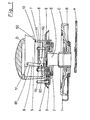
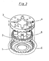
- the reporter group according to the invention essentially consists of a so-called fixed part comprising a rule holder A, a pad B carried by a support C 'which is provided with a toothed plate 1, and a rotating part comprising a handle D provided with a toothed plate 2 pivoting around a hub E.
- the plates 1 and 2 are concentric with the hub E and in the same plane, parallel to the rules.
- a third plate 3 identically toothed, concentric and parallel to the plates 1 and 2, movable between said plates perpendicular to the hub E, pushed towards the plate 1 by springs 4, meshes with the plates 1, 2 and makes them integral.
- This plate 3 movable along the hub E, is suspended from a plate 7 by columns 8 passing through the base 9 of the control handle D and rotating with it.
- the upward or downward movements of the plate 3 are obtained by a pressure exerted on a pusher 5 integrated in the handle D.
- the translation of the pusher 5 acts on a lever 6 whose support point 60 is located on the base 9, below of the plate 7.
- the arm 61 of the lever 6 pivots on a pin 51 of the pusher 5 and passes through an oblong opening 70 of the plate 7 so that its short arm 62 presses on the center 71 of plate 7 and lift it.
- a recess 50 of the pusher 5 allows the support force to be maintained by the installation of a latch 10 in said recess.
- the plate 3 can thus be kept clear to allow upe faster rotation of the rules.
- the plate 3 By unlocking the pusher 5 the plate 3 will be pushed towards the fixed plate 1 and the teeth of one will mesh in the teeth of the other at the same time as in the teeth of the pivoting plate 2.
- the snap-in position chosen predetermined will be maintained by all the teeth of the plates 1,2,3 whose contact surfaces are proportional to the number of teeth, which represents an important advantage compared to the pawl of known devices.
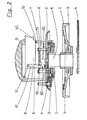
- FIG. 2 represents an embodiment of the invention comprising an orientable zero.
- the width of the teeth of the intermediate plate 3 is equal to the sum of the widths of the teeth of the two other plates 1,2.
- the contact surface of the teeth of the intermediate plate 3 is substantially equal to the sum of the surfaces of the teeth of the other two plates 1,2.
Landscapes
- A Measuring Device Byusing Mechanical Method (AREA)
- Drawing Aids And Blackboards (AREA)
- Food-Manufacturing Devices (AREA)
- Length-Measuring Instruments Using Mechanical Means (AREA)
- Toys (AREA)
- Organic Low-Molecular-Weight Compounds And Preparation Thereof (AREA)
- Acyclic And Carbocyclic Compounds In Medicinal Compositions (AREA)
Applications Claiming Priority (2)
| Application Number | Priority Date | Filing Date | Title |
|---|---|---|---|
| FR7815004A FR2425947A1 (fr) | 1978-05-16 | 1978-05-16 | Groupe rapporteur pour planche a dessiner |
| FR7815004 | 1978-05-16 |
Publications (1)
| Publication Number | Publication Date |
|---|---|
| EP0005573A1 true EP0005573A1 (de) | 1979-11-28 |
Family
ID=9208491
Family Applications (1)
| Application Number | Title | Priority Date | Filing Date |
|---|---|---|---|
| EP79200232A Withdrawn EP0005573A1 (de) | 1978-05-16 | 1979-05-11 | Zeichenkopf für Zeichenmaschine |
Country Status (14)
| Country | Link |
|---|---|
| US (1) | US4359824A (de) |
| EP (1) | EP0005573A1 (de) |
| JP (1) | JPS55500652A (de) |
| BE (1) | BE62T1 (de) |
| CH (1) | CH637575A5 (de) |
| DE (1) | DE2953023C2 (de) |
| FR (1) | FR2425947A1 (de) |
| GB (1) | GB2045448B (de) |
| IT (1) | IT1148298B (de) |
| NL (1) | NL7915023A (de) |
| OA (1) | OA06431A (de) |
| SE (1) | SE8004443L (de) |
| SU (1) | SU1074392A3 (de) |
| WO (1) | WO1979001076A1 (de) |
Families Citing this family (2)
| Publication number | Priority date | Publication date | Assignee | Title |
|---|---|---|---|---|
| DE3136872A1 (de) * | 1981-09-17 | 1983-03-31 | Möckel KG Feinmechanik, 6305 Buseck | Zeichenkopf fuer eine zeichenmaschine |
| US5598557A (en) * | 1992-09-22 | 1997-01-28 | Caere Corporation | Apparatus and method for retrieving and grouping images representing text files based on the relevance of key words extracted from a selected file to the text files |
Citations (3)
| Publication number | Priority date | Publication date | Assignee | Title |
|---|---|---|---|---|
| US2708791A (en) * | 1947-05-03 | 1955-05-24 | Universal Drafting Machine Cor | Drafting machine |
| DE943396C (de) * | 1953-01-25 | 1956-05-17 | Faber Castell A W | Einstellkopf fuer Zeichenmaschinen |
| US2900728A (en) * | 1957-03-11 | 1959-08-25 | Vard Products Inc | Drafting machine indexing means |
-
1978
- 1978-05-16 FR FR7815004A patent/FR2425947A1/fr active Granted
-
1979
- 1979-05-11 US US06/194,298 patent/US4359824A/en not_active Expired - Lifetime
- 1979-05-11 GB GB8012776A patent/GB2045448B/en not_active Expired
- 1979-05-11 NL NL7915023A patent/NL7915023A/nl unknown
- 1979-05-11 JP JP50083479A patent/JPS55500652A/ja active Pending
- 1979-05-11 CH CH331580A patent/CH637575A5/fr not_active IP Right Cessation
- 1979-05-11 EP EP79200232A patent/EP0005573A1/de not_active Withdrawn
- 1979-05-11 WO PCT/EP1979/000034 patent/WO1979001076A1/de not_active Ceased
- 1979-05-11 DE DE2953023A patent/DE2953023C2/de not_active Expired
- 1979-05-11 BE BEBTR62A patent/BE62T1/xx not_active IP Right Cessation
-
1980
- 1980-01-12 OA OA56991A patent/OA06431A/xx unknown
- 1980-01-15 SU SU802869453A patent/SU1074392A3/ru active
- 1980-06-16 SE SE8004443A patent/SE8004443L/ not_active Application Discontinuation
- 1980-07-02 IT IT86256/80A patent/IT1148298B/it active
Patent Citations (3)
| Publication number | Priority date | Publication date | Assignee | Title |
|---|---|---|---|---|
| US2708791A (en) * | 1947-05-03 | 1955-05-24 | Universal Drafting Machine Cor | Drafting machine |
| DE943396C (de) * | 1953-01-25 | 1956-05-17 | Faber Castell A W | Einstellkopf fuer Zeichenmaschinen |
| US2900728A (en) * | 1957-03-11 | 1959-08-25 | Vard Products Inc | Drafting machine indexing means |
Also Published As
| Publication number | Publication date |
|---|---|
| JPS55500652A (de) | 1980-09-18 |
| DE2953023C2 (de) | 1983-06-30 |
| FR2425947B1 (de) | 1980-10-31 |
| BE62T1 (fr) | 1980-04-25 |
| US4359824A (en) | 1982-11-23 |
| DE2953023A1 (de) | 1980-10-30 |
| NL7915023A (nl) | 1980-08-29 |
| SE8004443L (sv) | 1980-06-16 |
| WO1979001076A1 (fr) | 1979-12-13 |
| IT8086256A0 (it) | 1980-07-02 |
| GB2045448A (en) | 1980-10-29 |
| GB2045448B (en) | 1983-04-20 |
| FR2425947A1 (fr) | 1979-12-14 |
| SU1074392A3 (ru) | 1984-02-15 |
| CH637575A5 (fr) | 1983-08-15 |
| OA06431A (fr) | 1981-07-31 |
| IT1148298B (it) | 1986-11-26 |
Similar Documents
| Publication | Publication Date | Title |
|---|---|---|
| FR2487082A1 (fr) | Dispositif de reglage pour la platine porte-objet d'un instrument optique | |
| EP0005573A1 (de) | Zeichenkopf für Zeichenmaschine | |
| FR2841491A1 (fr) | Outil,notamment cle, dynamometrique comprenant des moyens cliquetants de reglage du couple | |
| FR2508196A1 (fr) | Mecanisme de guidage et d'actionnement, notamment pour derailleur de bicyclette | |
| FR2655896A1 (fr) | Plateau multibroche d'usinage de configuration variable. | |
| EP1977304B1 (de) | Verbesserungen an eingabeperipheriegeräten für computer oder dergleichen | |
| EP0191702B1 (de) | Automatisch positionierbarer Drehtisch zum Zeichnen | |
| CH631101A5 (en) | Disk fitted with a positioning device | |
| FR2514166A1 (fr) | Dispositif a levier de commande a mecanisme de centrage perfectionne | |
| FR2521913A1 (fr) | Tete a dessiner | |
| FR2644102A1 (fr) | Dispositif permettant de realiser une presse hydraulique a au moins un axe de poussee deplacable sur toute la zone de travail, a la demande | |
| CH84465A (fr) | Pied-a'1-coulisse | |
| FR2765598A1 (fr) | Dispositif de repassage comprenant une table a repasser et un repose-fer | |
| CH362598A (fr) | Dispositif de commande d'un diaphragme à lamelles pour objectif | |
| CH305144A (fr) | Plaque de guidage, notamment pour appareil à dessiner. | |
| CH298982A (fr) | Machine à couper. | |
| EP0347385A1 (de) | Aneroid-Barometer-Mechanismus | |
| EP0171301A1 (de) | Drehkreuz für die Durchlasskontrolle an einem bestimmten Ort | |
| CH659615A5 (en) | Workbench | |
| CH691879A5 (fr) | Appareil de mesure de longueurs. | |
| EP0083956A1 (de) | Betätigungseinrichtung für einen Winkeleinstellmechanismus eines Parallellinealzeichenkopfes | |
| CH387308A (fr) | Calibre | |
| CH588950A5 (en) | Pantograph wedding ring engraving machine - has right angle block ring support on two way slide and incorporates dividing head | |
| EP0041414A1 (de) | Spannvorrichtung | |
| FR2622141A1 (fr) | Dispositif de reglage angulaire pour porte-outil multichanfreins |
Legal Events
| Date | Code | Title | Description |
|---|---|---|---|
| PUAI | Public reference made under article 153(3) epc to a published international application that has entered the european phase |
Free format text: ORIGINAL CODE: 0009012 |
|
| AK | Designated contracting states |
Designated state(s): AT BE CH DE GB IT LU NL SE |
|
| STAA | Information on the status of an ep patent application or granted ep patent |
Free format text: STATUS: THE APPLICATION IS DEEMED TO BE WITHDRAWN |
|
| 110E | Request filed for conversion into a national patent application [according to art. 135 epc] | ||
| 18D | Application deemed to be withdrawn | ||
| RIN1 | Information on inventor provided before grant (corrected) |
Inventor name: BRUNEAU, ALAIN MAURICE |