EP0347648A1 - Procédé de reproduction d'image avec un écran luminescent de mémorisation - Google Patents
Procédé de reproduction d'image avec un écran luminescent de mémorisation Download PDFInfo
- Publication number
- EP0347648A1 EP0347648A1 EP89110314A EP89110314A EP0347648A1 EP 0347648 A1 EP0347648 A1 EP 0347648A1 EP 89110314 A EP89110314 A EP 89110314A EP 89110314 A EP89110314 A EP 89110314A EP 0347648 A1 EP0347648 A1 EP 0347648A1
- Authority
- EP
- European Patent Office
- Prior art keywords
- pole pieces
- storage
- scanning
- screen
- drive roller
- Prior art date
- Legal status (The legal status is an assumption and is not a legal conclusion. Google has not performed a legal analysis and makes no representation as to the accuracy of the status listed.)
- Withdrawn
Links
Images

Classifications
-
- H—ELECTRICITY
- H04—ELECTRIC COMMUNICATION TECHNIQUE
- H04N—PICTORIAL COMMUNICATION, e.g. TELEVISION
- H04N5/00—Details of television systems
- H04N5/30—Transforming light or analogous information into electric information
- H04N5/32—Transforming X-rays
-
- G—PHYSICS
- G01—MEASURING; TESTING
- G01T—MEASUREMENT OF NUCLEAR OR X-RADIATION
- G01T1/00—Measuring X-radiation, gamma radiation, corpuscular radiation, or cosmic radiation
- G01T1/16—Measuring radiation intensity
- G01T1/20—Measuring radiation intensity with scintillation detectors
- G01T1/2012—Measuring radiation intensity with scintillation detectors using stimulable phosphors, e.g. stimulable phosphor sheets
- G01T1/2014—Reading out of stimulable sheets, e.g. latent image
-
- G—PHYSICS
- G03—PHOTOGRAPHY; CINEMATOGRAPHY; ANALOGOUS TECHNIQUES USING WAVES OTHER THAN OPTICAL WAVES; ELECTROGRAPHY; HOLOGRAPHY
- G03B—APPARATUS OR ARRANGEMENTS FOR TAKING PHOTOGRAPHS OR FOR PROJECTING OR VIEWING THEM; APPARATUS OR ARRANGEMENTS EMPLOYING ANALOGOUS TECHNIQUES USING WAVES OTHER THAN OPTICAL WAVES; ACCESSORIES THEREFOR
- G03B42/00—Obtaining records using waves other than optical waves; Visualisation of such records by using optical means
- G03B42/02—Obtaining records using waves other than optical waves; Visualisation of such records by using optical means using X-rays
Definitions
- the invention relates to a reading device for a storage fluorescent screen, in which X-ray images are stored latently and which has a stimulable phosphor layer and a layer of magnetic material, with a scanning device which effects a line-shaped scanning by means of a scanning beam from a radiation source, so that the storage fluorescent screen illuminates pixel by pixel is excited with a transport device with magnetic holding means for the storage luminescent screen and with a detector device for areal detection of the light emitted by the storage luminescent screen.
- EP-A-0 098 596 describes such a reading device in which the storage phosphor screen is held on an endless belt by magnetic force.
- the belt can be designed such that magnets are embedded in it, which hold the storage fluorescent screen with its layer of magnetic material on the belt.
- a magnet is provided, which is arranged below the belt, so that the storage phosphor screen is pressed onto the belt due to the force of the magnet.
- such a device is complex to manufacture. Difficulties also arise due to poor synchronization and exact positioning of the storage fluorescent screen, since the belt must be flexible and, for example, height fluctuations can occur during the feed.
- the invention is based on the object of creating a readout device of the type mentioned at the outset which has a simple structure and at least one in the area of the scanning three-dimensional exact positioning.
- the transport device has a magnetic drive roller in the region of the scanning beam, which effects the transport of the storage fluorescent screen.
- This fixed drive roller ensures that the storage fluorescent screen is held vertically and laterally in the area of the scanning beam, so that no distortions of the image as a result of deviations can occur.
- a simple and variable construction of the drive roller is achieved if it has an axis made of non-magnetic material, onto which ring magnets are attached, which are delimited on both sides by annular pole pieces, and if there are spacers made of non-magnetic material between the pole pieces.
- the drive axis is easier to manufacture if the pole pieces have a larger diameter than the ring magnets.
- the frictional force and thus the synchronism as well as the accuracy of the alignment are increased if at least between the pole pieces a filling of compressible material is arranged, which projects beyond the diameter of the pole pieces.
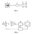
- FIG. 1 shows a high-voltage generator 1 that feeds an X-ray tube 2 that emits X-rays that penetrate a patient 3.
- the X-rays weakened by the patient 3 in accordance with its transparency fall onto a luminescence storage luminescent screen 4.
- This striking radiation image generates defect electrons in the storage luminescent screen 4, which are stored in potential traps, so that a latent image is stored in the storage luminescent screen 4.
- the storage phosphor screen 4 is usually scanned pixel by pixel by a radiation source, for example a laser 5, so that the electrons stored in the traps can be excited and can fall back into recombination centers, the energy difference is emitted in the form of light quanta. This makes it possible to read the x-ray image stored in this way from the storage fluorescent screen 4.
- a radiation source for example a laser 5
- the deflection device 6 for the scanning beam 7 can consist, for example, of a deflection mirror for the vertical deflection.
- the storage fluorescent screen is conveyed line by line by a transport device shown in more detail in FIG.
- the light emitted by the storage luminescent screen 4 is detected by a detector device, which consists of a light guide 8, which guides the light onto a detector 9, which detects the brightness of the scanned pixels and converts them into an electrical signal.
- a detector device which consists of a light guide 8, which guides the light onto a detector 9, which detects the brightness of the scanned pixels and converts them into an electrical signal.
- This electrical signal is fed to a playback circuit 10, which generates a video signal for display on a monitor 11 from the individual analog output signals of the detector 9.
- a control device 12 effects the synchronization of the deflection device 6, the playback circuit 10 and the monitor 11 during playback.
- the playback circuit 10 can have image memories, a processing circuit and converters in a known manner.
- FIG. 3 shows the transport device for the storage fluorescent screen 4, which has a two-layer structure.
- the upward-facing phosphor layer 13 is scanned in a line shape (arrows 27) from above by the scanning beam 7 shown in FIG.
- the phosphor layer 13 is applied to a layer 14 made of magnetic material, for example sheet steel.
- the storage fluorescent screen 4 is held by a drive roller 15 made of magnetic material in the area of the line-shaped scanning by the scanning beam 7 and pressed onto the drive roller 15. After a line has been scanned, the drive roller 15 can be rotated step by step in the direction of an arrow 28, so that the storage phosphor screen 4 moves in the direction of an arrow 29 by the distance of a scan line. The next line can now be scanned by the scanning beam 7.
- Guides 16 and 17 keep the storage phosphor screen 4 outside the scanning range. In order to achieve a constant line spacing, it can be expedient to drive the drive roller 15 at a constant angular velocity.
- the drive roller 15 of the transport device is shown in section. It has an axis 18 made of non-magnetic material, which is provided with bearing pins 19. Ring magnets 20, whose magnetic fields have an axial direction, are plugged onto the axis 18. The ring magnets 20 are laterally limited by pole pieces 21 and 22 which are also plugged onto the axis 18. Spacers 23 and 24 of different lengths keep the magnet assemblies 20 to 22 at the desired, required distance. This distance can be given, for example, by requiring that at least the side and the center of the storage fluorescent screen be detected and held for each size of the storage fluorescent screen. This results in that a magnet arrangement 20 to 22 is located in the center of the drive roller 15, while at the edge of the drive roller 15 a plurality of magnet arrangements 20 to 22 are provided, the spacing of the pairs of which correspond to the different dimensions of the storage phosphor screen 4.
- the clamping pieces 25 can be nuts which are held in place by screw threads on the axis 18. But you can also be permanently connected to the axis 18.
- this can be provided at least in the region between the pole pieces 21 and 22 belonging to a ring magnet 20, through which the magnetic attraction is exerted, with a filling 26 made of compressible material, which the pole pieces 21 and 22 dominates in its outer diameter.
- These fillings 26 can be made of foam, for example. Due to the attractive force of the magnet arrangements 20 to 22 acting on the layer 14 of the storage fluorescent screen 4, the fillings 26 are pressed together, so that they also take the storage fluorescent screen 4 with them, since the frictional force increases.
- the ring-shaped pole pieces 21 and 22 have a larger diameter than the ring magnets 20. This simplifies the manufacture of the magnet arrangements 20 to 22.
- the pole pieces 21 and 22 can easily be produced with the required outer diameter and the required smooth surface, since for the pole pieces 21 and 22 an easy-to-process material can be selected.
- the one drive roller 15 shown it is also possible to use a plurality of magnetic drive rollers which, for example, effect the transport from a removal station for the storage fluorescent screen from a cassette to the scanning area. Furthermore, the use of additional drive rollers increases the accuracy of the alignment of the storage phosphor screen 4. Thus, for example, approximately half the distance of the dimension of the smallest storage phosphor screen 4 to be used, a further drive roller can be provided in front of and behind the drive roller 15, so that the storage phosphor screen 4 is always at least two drive rollers is held so that lateral twisting is excluded.
Landscapes
- Physics & Mathematics (AREA)
- General Physics & Mathematics (AREA)
- Life Sciences & Earth Sciences (AREA)
- Signal Processing (AREA)
- Multimedia (AREA)
- Health & Medical Sciences (AREA)
- Engineering & Computer Science (AREA)
- High Energy & Nuclear Physics (AREA)
- Molecular Biology (AREA)
- Spectroscopy & Molecular Physics (AREA)
- Conversion Of X-Rays Into Visible Images (AREA)
- Radiography Using Non-Light Waves (AREA)
- Feeding Of Articles By Means Other Than Belts Or Rollers (AREA)
Applications Claiming Priority (2)
| Application Number | Priority Date | Filing Date | Title |
|---|---|---|---|
| DE3820938 | 1988-06-21 | ||
| DE3820938 | 1988-06-21 |
Publications (1)
| Publication Number | Publication Date |
|---|---|
| EP0347648A1 true EP0347648A1 (fr) | 1989-12-27 |
Family
ID=6356928
Family Applications (1)
| Application Number | Title | Priority Date | Filing Date |
|---|---|---|---|
| EP89110314A Withdrawn EP0347648A1 (fr) | 1988-06-21 | 1989-06-07 | Procédé de reproduction d'image avec un écran luminescent de mémorisation |
Country Status (3)
| Country | Link |
|---|---|
| US (1) | US4973134A (fr) |
| EP (1) | EP0347648A1 (fr) |
| JP (1) | JPH0239036A (fr) |
Cited By (1)
| Publication number | Priority date | Publication date | Assignee | Title |
|---|---|---|---|---|
| DE4191828C2 (de) * | 1990-07-30 | 2002-03-28 | Orion Yhtymae Oy | Verfahren und Vorrichtung zum Aufzeichnen von Informationen von einer belichteten verschiebbaren Platte einer RIM-Kassette |
Families Citing this family (14)
| Publication number | Priority date | Publication date | Assignee | Title |
|---|---|---|---|---|
| US5635728A (en) * | 1995-06-19 | 1997-06-03 | Denoptix, Inc. | Rotating scanner system for reading multiple storage layer radiation screens |
| JP3458035B2 (ja) * | 1996-02-05 | 2003-10-20 | 富士写真フイルム株式会社 | 走査装置 |
| US6624438B2 (en) | 1997-11-20 | 2003-09-23 | Orex Computed Radiography Ltd. | Scanning apparatus |
| US6198111B1 (en) * | 1998-10-14 | 2001-03-06 | Alara, Inc. | Scanning system with flexible drive assembly |
| JP2002537667A (ja) | 1998-11-25 | 2002-11-05 | フォーマックス コーポレイション | デュアルヘッド蛍光体スクリーンスキャナ |
| EP1065671A1 (fr) * | 1999-06-22 | 2001-01-03 | Agfa-Gevaert N.V. | Procédé de formation d'image, dosimétrie et surveillance individuelle |
| US6420724B1 (en) | 1999-06-22 | 2002-07-16 | Agfa-Gevaert | Method of image formation, dosimetry and personal monitoring |
| US20030042445A1 (en) * | 2001-08-30 | 2003-03-06 | Mitchell Christopher R. | Apparatus for reading storage layer radiation screens |
| WO2004102627A2 (fr) * | 2003-05-08 | 2004-11-25 | Alara, Inc. | Procede et dispositif pour effacement d'images radiographiques |
| GB2407971A (en) * | 2003-11-15 | 2005-05-18 | Mel Colton | Media providing seat |
| DE102005046248A1 (de) * | 2005-09-27 | 2007-03-29 | Dürr Dental GmbH & Co. KG | Vorrichtung zum Auslesen von insbesondere flexiblen Speicherfolien |
| EP2568333B1 (fr) * | 2011-09-06 | 2016-11-09 | Agfa HealthCare N.V. | Dispositif, système et procédé destinés à la lecture d'informations radiographiques stockées dans des plaques fluorescentes de mémoire |
| ES2453290T3 (es) * | 2011-09-06 | 2014-04-07 | Agfa Healthcare N.V. | Dispositivo y sistema para la lectura de información de rayos X almacenada en placas luminiscentes de almacenamiento |
| EP2921881B1 (fr) * | 2014-03-18 | 2018-11-28 | Agfa Nv | Ensemble plaque de stockage phosphoreuse, cassette de radiographie et système de lecture de telles plaques |
Citations (2)
| Publication number | Priority date | Publication date | Assignee | Title |
|---|---|---|---|---|
| EP0098596A2 (fr) * | 1982-07-06 | 1984-01-18 | Fuji Photo Film Co., Ltd. | Méthode et dispositif de reproduction d'images de rayonnement |
| EP0098574A2 (fr) * | 1982-07-06 | 1984-01-18 | Fuji Photo Film Co., Ltd. | Procédé et appareil pour la lecture d'images de radiation |
Family Cites Families (2)
| Publication number | Priority date | Publication date | Assignee | Title |
|---|---|---|---|---|
| US1444999A (en) * | 1920-11-20 | 1923-02-13 | American Sheet | Magnetic conveyer |
| JPS5817767A (ja) * | 1981-07-23 | 1983-02-02 | Fuji Photo Film Co Ltd | 画像走査装置 |
-
1989
- 1989-04-03 US US07/332,494 patent/US4973134A/en not_active Expired - Fee Related
- 1989-06-07 EP EP89110314A patent/EP0347648A1/fr not_active Withdrawn
- 1989-06-14 JP JP1152057A patent/JPH0239036A/ja active Pending
Patent Citations (2)
| Publication number | Priority date | Publication date | Assignee | Title |
|---|---|---|---|---|
| EP0098596A2 (fr) * | 1982-07-06 | 1984-01-18 | Fuji Photo Film Co., Ltd. | Méthode et dispositif de reproduction d'images de rayonnement |
| EP0098574A2 (fr) * | 1982-07-06 | 1984-01-18 | Fuji Photo Film Co., Ltd. | Procédé et appareil pour la lecture d'images de radiation |
Cited By (1)
| Publication number | Priority date | Publication date | Assignee | Title |
|---|---|---|---|---|
| DE4191828C2 (de) * | 1990-07-30 | 2002-03-28 | Orion Yhtymae Oy | Verfahren und Vorrichtung zum Aufzeichnen von Informationen von einer belichteten verschiebbaren Platte einer RIM-Kassette |
Also Published As
| Publication number | Publication date |
|---|---|
| US4973134A (en) | 1990-11-27 |
| JPH0239036A (ja) | 1990-02-08 |
Similar Documents
| Publication | Publication Date | Title |
|---|---|---|
| EP0347648A1 (fr) | Procédé de reproduction d'image avec un écran luminescent de mémorisation | |
| DE3819496C2 (fr) | ||
| DE3586996T2 (de) | Verfahren und geraet zu roentgenstrahlenuntersuchung. | |
| DE19604802C2 (de) | Abbildungssystem und Verfahren zum Erzeugen einer Querschnittsabbildung eines Objekts | |
| DE69414879T2 (de) | Gas-ionisations-netzdetektoren für die radiographie | |
| DE4409365C1 (de) | Röntgencomputertomograph | |
| DE1589950A1 (de) | Strahlungsabtastvorrichtung | |
| DE1943140A1 (de) | Elektronenstrahl-Geraet | |
| EP0358796B1 (fr) | Dispositif de diagnostic à rayons X avec un écran luminescent à mémoire | |
| DE2025473C3 (de) | Vorrichtung zum Auswerten eines Strahlungsenergiemusters | |
| EP0346722B1 (fr) | Ecran luminescent de mémorisation pour la détection d'image de rayonnement X | |
| DE2254916B2 (de) | Verfahren und Vorrichtung zur Anfertigung einer bleibenden Kopie von in Form eines Fernsehrasters vorliegenden Eingangsinformationen | |
| EP0456322B1 (fr) | Installation de production de radiographies | |
| DE102009043423A1 (de) | Röntgenaufnahmeverfahren und Röntgenaufnahmesystem | |
| DE3534768A1 (de) | Anordnung zum erzeugen von roentgenaufnahmen mittels eines fotoleiters | |
| DE19608497C2 (de) | Röntgendiagnostikgerät | |
| DE8816464U1 (de) | Auslesevorrichtung für einen Speicherleuchtschirm | |
| EP2290404A1 (fr) | Renforçateur structurel appliqué à une zone de court-circuit d'élément structurel | |
| EP0363522B1 (fr) | Ecran de mémorisation pour la détection d'image de rayonnement X | |
| EP0191322A1 (fr) | Dispositif pour la reproduction d'une image rayons X au moyen de radiographie par ordinateur | |
| DE3433141C2 (fr) | ||
| EP0495138B1 (fr) | Ecran de mémorisation pour la reproduction d'image | |
| EP0387369A1 (fr) | Dispositif de radiodiagnostic avec un écran luminescent de mémorisation | |
| WO1997033159A1 (fr) | Procede et dispositif d'inspection radioscopique des soudures d'ensembles de composants electroniques | |
| EP0804853B1 (fr) | Dispositif optique et procede pour transmettre et convertir des images primaires radiographiques |
Legal Events
| Date | Code | Title | Description |
|---|---|---|---|
| PUAI | Public reference made under article 153(3) epc to a published international application that has entered the european phase |
Free format text: ORIGINAL CODE: 0009012 |
|
| AK | Designated contracting states |
Kind code of ref document: A1 Designated state(s): BE DE FR GB |
|
| 17P | Request for examination filed |
Effective date: 19900126 |
|
| 17Q | First examination report despatched |
Effective date: 19910204 |
|
| STAA | Information on the status of an ep patent application or granted ep patent |
Free format text: STATUS: THE APPLICATION HAS BEEN WITHDRAWN |
|
| 18W | Application withdrawn |
Withdrawal date: 19910415 |