EP0363522B1 - Ecran de mémorisation pour la détection d'image de rayonnement X - Google Patents
Ecran de mémorisation pour la détection d'image de rayonnement X Download PDFInfo
- Publication number
- EP0363522B1 EP0363522B1 EP88117155A EP88117155A EP0363522B1 EP 0363522 B1 EP0363522 B1 EP 0363522B1 EP 88117155 A EP88117155 A EP 88117155A EP 88117155 A EP88117155 A EP 88117155A EP 0363522 B1 EP0363522 B1 EP 0363522B1
- Authority
- EP
- European Patent Office
- Prior art keywords
- diagnostic device
- ray diagnostic
- detector
- light guide
- ray
- Prior art date
- Legal status (The legal status is an assumption and is not a legal conclusion. Google has not performed a legal analysis and makes no representation as to the accuracy of the status listed.)
- Expired - Lifetime
Links
Images

Classifications
-
- H—ELECTRICITY
- H04—ELECTRIC COMMUNICATION TECHNIQUE
- H04N—PICTORIAL COMMUNICATION, e.g. TELEVISION
- H04N1/00—Scanning, transmission or reproduction of documents or the like, e.g. facsimile transmission; Details thereof
- H04N1/024—Details of scanning heads ; Means for illuminating the original
- H04N1/028—Details of scanning heads ; Means for illuminating the original for picture information pick-up
- H04N1/0281—Details of scanning heads ; Means for illuminating the original for picture information pick-up with means for collecting light from a line or an area of the original and for guiding it to only one or a relatively low number of picture element detectors
-
- G—PHYSICS
- G01—MEASURING; TESTING
- G01T—MEASUREMENT OF NUCLEAR OR X-RADIATION
- G01T1/00—Measuring X-radiation, gamma radiation, corpuscular radiation, or cosmic radiation
- G01T1/16—Measuring radiation intensity
- G01T1/20—Measuring radiation intensity with scintillation detectors
- G01T1/2012—Measuring radiation intensity with scintillation detectors using stimulable phosphors, e.g. stimulable phosphor sheets
- G01T1/2014—Reading out of stimulable sheets, e.g. latent image
Definitions
- the invention relates to an X-ray diagnostic device according to the preamble of claim 1.
- Such readout devices serve to excite the latent storage phosphor image contained in the storage phosphor screen, which emits light, the brightness of which depends on the previous exposure by X-rays.
- Such a reading device is described in US Pat. No. 4,629,890, in which a tubular light guide is arranged above the storage phosphor screen, the inner walls of which are mirrored.
- the tubular light guide has a slit-shaped passage through which the scanning beam, which is generated by a radiation source and deflected by a rotatable mirror, can pass through, so that a complete line of the storage phosphor screen can be scanned and excited.
- the storage fluorescent screen Due to the excitation, the storage fluorescent screen emits pixel-by-pixel light which is reflected by the walls of the tubular light guide and directed to two detectors arranged on the sides. These generate an electrical signal that corresponds to the brightness of the light emitted by the pixel of the storage fluorescent screen.
- the tube diameter must not be too small, otherwise there will be too many reflections that weaken the light too much.
- the light that strikes the end faces must be converted with good efficiency.
- Photomultipliers with side windows have incident light cathodes, ie the cathode plate is located some distance behind the window so that the electrons emitting to the front can be extracted. So that most of the from the tubular Light guide emerging light is detected, multiplier with side windows with their dimensions must be significantly larger than the optimal tube diameter. There are no such photomultipliers with a side window with large dimensions.
- Photomultipliers with transmitted light cathodes need only have a diameter the size of the diameter of the tube, since the photocathode is almost at the tube ends. This in turn requires a very bulky design because the photomultipliers are flanged in the tube axis.
- the lateral arrangement of the detectors results in a sensitivity curve which favors the lateral areas of the storage fluorescent screen, since these are more direct, i.e. hit the detector with fewer reflections.
- the most important image information is mostly in the center of the image, so that it appears weakened compared to the edge areas.
- EP-A-0 209 119 shows an image reading device in which a line-shaped detector engages in an opening in the wall of a tubular light guide, or is assigned in front of a light guide with an opening facing the detector and the storage phosphor screen.
- the openings of the light guides are aligned parallel to the surface of the fluorescent screen.
- the light guides are not closed off by reflective surfaces, so that lost light can escape.
- the installation of the detector in the tubular light guide results in difficult manufacture and assembly.
- the second embodiment with a quarter shell in which the detector is arranged obliquely, a not insignificant proportion of the emitted light is lost and on the other hand light is also detected that does not belong to the scanned pixel or the scanning line, so that the resolution is reduced.
- EP-A-0 210 505 there is a read-out device for one Storage fluorescent screen described, in which the light emitted by the storage fluorescent screen is guided via a light guide to a detector.
- An elliptical mirror which also corresponds to a quarter shell, is arranged in front of the light guide, with the scanning line in one focus and the input surface of the light guide in the other focus.
- two separate light guides are required.
- the invention is based on the object of providing an X-ray diagnostic device of the type mentioned at the outset, in which the readout unit has a compact and simple structure and ensures reliable readout, in particular of the image-important parts in the center of the storage fluorescent screen. Furthermore, there should be little reflection paths of the emitted light.
- the object is achieved by the features specified in the characterizing part of claim 1.
- This results in a compact structure of the readout unit, since the detector is attached to the tubular light guide perpendicular to the tube axis and line direction. Due to the integration of the detector with the tubular light guide and the preferred arrangement of the detector near the center thereof, the light emitted at least by the pixels located in the center requires only a few reflections, so that it reaches the light-sensitive input surface of the detector almost without being weakened. Furthermore, the detector is arranged near the scanning line, so that the reflection paths of the emitted light also result from this.
- the light output and the linearity of the brightness can be increased if two detectors are arranged next to one another.
- a secure attachment of the detectors and a stable arrangement of the readout device with high light guidance is achieved when the remaining free area of the half-shell is covered by a mirrored holder for the detectors and when the laser beam is carried out between the half-shell and the holder of the detectors.
- the light of the laser beam reflected from the surface of the storage fluorescent screen can be eliminated if a filter is arranged in front of the detectors. It has proven to be advantageous if the tubular light guide has a round or elliptical cross section. The The number of reflections can be kept small if the diameter of the tubular light guide is 100-120 mm.
- a high-quality mirroring with almost 100% reflection can be obtained if the mirrored surfaces of the tubular light guide consist of barium sulfate (BaSO4).
- the brightness curve in the line direction can be corrected if the image display system is designed in such a way that each scanning line is corrected in the line direction in accordance with the locally different optical coupling quality.
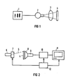
- FIG. 1 shows a high-voltage generator 1 that feeds an X-ray tube 2 that emits X-rays that penetrate a patient 3.
- the X-rays weakened by the patient 3 in accordance with its transparency fall on a luminescence storage luminescent screen 4.
- This striking radiation image generates defect electrons in the storage luminescent screen 4, which are held in potential traps of the phosphor, so that a latent image is stored in the storage luminescent screen.
- the storage fluorescent screen is used to display the latent image 4, as shown in FIG. 2, scanned pixel by pixel by a laser beam 5, which is generated by a laser 6 and is deflected line by line by a deflection device 7 over the surface of the fluorescent screen 4.
- the deflection device 7 for the laser 6 can consist, for example, of a deflection mirror for the vertical and an electro-optical beam deflector for the horizontal deflection.
- the vertical deflection can also be achieved by a parallel advancement of the fluorescent screen 4 perpendicular to the scanning line, as is required for the reading device according to the invention.
- An optical fiber optic 8 detects the light emitted by the storage fluorescent screen 4 and directs it to a detector device 9, which detects the brightness of the scanned pixels and converts it into an electrical signal. This signal is fed to a playback circuit 10, which generates a video signal for display on a monitor 11 from the individual analog output signals of the detector device 9.
- the playback circuit 10 may include image memories, processing circuits, A / D and D / A converters.
- a control device 12 generates the control clocks for synchronizing the deflection device 7, the reproduction circuit 10 and the monitor 11.
- the light guide optics 8 consists of a tubular light guide 13 which has a half-shell 14 with a circular diameter.
- the opening of the half-shell 14 is almost perpendicular to the storage fluorescent screen 4 and runs parallel to the alignment of the scanning line 15 which the laser beam 5 sweeps over the storage fluorescent screen 4.
- the half-shell 14 is laterally delimited by two plates 16 and 17, on which fastening plates 18 and 19 are attached for the half-shell 14.
- a holder 20 is attached to the half-shell 14 on the plates 16 and 17 and, as can be seen from FIG.
- the detectors 21 are surrounded by shields 22 and 23. Filters 24 are arranged in front of the detectors 21. Photomultipliers with transmitted light cathodes can be used as detectors 21.
- the surfaces 25 of the plates 16 and 17, the inner surface 26 of the half-shell 14 and the surface 27 of the holder 20 are mirrored. This can be done according to the invention by barium sulfate (BaSO4), which has a degree of reflection of almost 100%.
- the laser beam 5 sweeps over the storage fluorescent screen 4 in the form of the scanning line 15, so that the pixels of the storage fluorescent screen 4 lying on this scanning line 15 are excited to light up in succession.
- the light emitted by the excited pixels spreads to all sides and is reflected by the mirrored surfaces 25 to 27 until it falls on the light-sensitive surfaces of the photocathodes 29 of the detectors 21, so that this light can contribute to the electrical signal.
- the pixels which are in the vicinity of the detectors 21 require only a short path and a few reflections until they fall on the photocathode 29 of the nearby detector. As a result, this portion of light reaches the photocathode 29 almost without attenuation.
- the pixels that lie between the two detectors 21 emit light, which, although it takes a little longer, can fall on both detectors 21, so that this light is also almost unattenuated is detected by the detectors 21. Only the proportions of the pixels, which are to the side of the detectors 21 provide a somewhat weakened signal. However, since there are mostly only irrelevant parts of the image in these areas, this is not perceived as disturbing. However, there is also the possibility of correcting the lateral drops in the light intensities of the storage luminous image as a result of changed light transmission paths from line to line in a computer arranged in the reproduction circuit 10.
- the maximum sensitivity of the readout device is in the middle, which, as already mentioned, contains the essential image information.
- a drop in sensitivity at the edge of the image is countered by a corresponding correction in the playback circuit, in that the locally different optical coupling qualities of the storage fluorescent screen to the detector are calculated in line width as a percentage in each scan line as correction values.
- the result is then a full scan width of e.g. 40 cm homogeneous-looking storage phosphor image that only contains the modulation of the radiation images exposed by the X-rays and no other interference. In this way, e.g. Thorax images in thoracic wall areas that would be on the edge of the image of the imaging plate can be diagnosed well.
Landscapes
- Molecular Biology (AREA)
- Spectroscopy & Molecular Physics (AREA)
- Signal Processing (AREA)
- Physics & Mathematics (AREA)
- Health & Medical Sciences (AREA)
- Life Sciences & Earth Sciences (AREA)
- General Physics & Mathematics (AREA)
- High Energy & Nuclear Physics (AREA)
- Multimedia (AREA)
- Engineering & Computer Science (AREA)
- Radiography Using Non-Light Waves (AREA)
- Conversion Of X-Rays Into Visible Images (AREA)
- Apparatus For Radiation Diagnosis (AREA)
- Image Input (AREA)
- Transforming Light Signals Into Electric Signals (AREA)
- Closed-Circuit Television Systems (AREA)
- Facsimile Scanning Arrangements (AREA)
Claims (9)
- Appareil de radiodiagnostic comportant un écran luminescent de stockage (4) servant à stocker à l'état latent l'image radiographique respective, comportant un dispositif de lecture (5 à 12), dans lequel, pour la reproduction de l'image, l'écran luminescent de stockage (4) est excité, pour s'éclairer, au niveau des points d'image, sous l'effet d'un balayage, d'une certaine étendue, réalisé au moyen d'un faisceau de balayage (5) d'une source de rayonnement (6), un dispositif de détection (8,9) servant à détecter, sur une certaine étendue, la lumière émise par l'écran luminescent de stockage (4), et un système de reproduction d'images (10,11), et dans laquelle le dispositif de détection (8,9) possède un guide de lumière tubulaire métallisé (8,13) servant à détecter une ligne complète balayée (15) sur l'écran luminescent de stockage (4), et au moins un détecteur (21), tandis que le guide de lumière (8,13) est pourvu d'un passage en forme de fente (28) pour le faisceau de balayage (5), et dans lequel une ouverture servant à recevoir le détecteur (21) est ménagée dans la paroi du guide de lumière tubulaire (8,13), le détecteur (21) est agencé de telle sorte que sa surface photosensible est parallèle à la ligne balayée (15) et le guide de lumière tubulaire (8,13) possède une demi-coque (14), dont l'ouverture est approximativement perpendiculaire au plan prévu pour l'écran luminescent de stockage (4) et est approximativement parallèle à la direction des lignes devant être explorées, caractérisé par le fait que le détecteur (21) est disposé par rapport à l'ouverture de la demi-coque (14) de telle sorte que sa surface photosensible est parallèle à la surface de l'ouverture, les dimensions perpendiculaires des deux surfaces étant presque identiques, et que le passage (28) est disposé entre la demi-coque (14) et le détecteur et que le guide de lumière tubulaire (8,13) est fermé, au niveau de ses extrémités latérales, par des plaques (16,17) possédant des surfaces métallisées (25).
- Installation de radiodiagnostic suivant la revendication 1, caractérisée par le fait que deux détecteurs (21) sont disposés côte-à-côte.
- Installation de radiodiagnostic suivant la revendication 1 ou 2, caractérisée par le fait que la surface libre, qui subsiste encore, de l'ouverture de la demi-coque (14) est fermée par un support métallisé (20) pour les détecteurs (21) et que le faisceau laser (5) est transmis entre la demi-coque (14) et le support (20).
- Installation de radiodiagnostic suivant l'une des revendications 1 à 3, caractérisée par le fait qu'un filtre (24) est placé devant les détecteurs (21).
- Installation de radiodiagnostic suivant l'une des revendications 1 à 4, caractérisée par le fait que le guidede lumière tubulaire (8,13) possède une section transversale circulaire.
- Installation de radiodiagnostic suivant l'une des revendications 1 à 5, caractérisée par le fait que le guidede lumière tubulaire (8,13) possède une section transversale elliptique.
- Installation de radiodiagnostic suivant l'une des revendications 1 a 6, caractérisée par le fait que le diamètre du guide de lumière tubulaire (8,13) est égal à 100-120 mm.
- Installation de radiodiagnostic suivant l'une des revendications 1 à 7, caractérisée par le fait que les surfaces métallisées du guidede lumière tubulaire (8,13) sont constituées par du sulfate de baryum (BaSO₄).
- Installation de radiodiagnostic suivant l'une des revendications 1 à 8, caractérisée par le fait que le système de reproduction d'images (10,11) est agencé de telle sorte que chaque ligne de balayage est corrigée dans la direction des lignes en fonction de la qualité de couplage optique, qui varie localement.
Priority Applications (4)
| Application Number | Priority Date | Filing Date | Title |
|---|---|---|---|
| DE8888117155T DE3877202D1 (de) | 1988-10-14 | 1988-10-14 | Roentgendiagnostikeinrichtung mit einem speicherleuchtschirm. |
| EP88117155A EP0363522B1 (fr) | 1988-10-14 | 1988-10-14 | Ecran de mémorisation pour la détection d'image de rayonnement X |
| US07/418,256 US5017781A (en) | 1988-10-14 | 1989-10-06 | Read-out system for a luminescent storage screen in an X-ray diagnostics installation |
| JP1989118689U JPH0736363Y2 (ja) | 1988-10-14 | 1989-10-09 | 記憶蛍光板を用いたx線診断装置 |
Applications Claiming Priority (1)
| Application Number | Priority Date | Filing Date | Title |
|---|---|---|---|
| EP88117155A EP0363522B1 (fr) | 1988-10-14 | 1988-10-14 | Ecran de mémorisation pour la détection d'image de rayonnement X |
Publications (2)
| Publication Number | Publication Date |
|---|---|
| EP0363522A1 EP0363522A1 (fr) | 1990-04-18 |
| EP0363522B1 true EP0363522B1 (fr) | 1992-12-30 |
Family
ID=8199460
Family Applications (1)
| Application Number | Title | Priority Date | Filing Date |
|---|---|---|---|
| EP88117155A Expired - Lifetime EP0363522B1 (fr) | 1988-10-14 | 1988-10-14 | Ecran de mémorisation pour la détection d'image de rayonnement X |
Country Status (4)
| Country | Link |
|---|---|
| US (1) | US5017781A (fr) |
| EP (1) | EP0363522B1 (fr) |
| JP (1) | JPH0736363Y2 (fr) |
| DE (1) | DE3877202D1 (fr) |
Families Citing this family (5)
| Publication number | Priority date | Publication date | Assignee | Title |
|---|---|---|---|---|
| DE59103284D1 (de) * | 1991-01-15 | 1994-11-24 | Siemens Ag | Auslesevorrichtung mit einem Speicherleuchtschirm. |
| DE4115725A1 (de) * | 1991-05-14 | 1992-11-19 | Siemens Ag | Auslesevorrichtung fuer einen speicherleuchtschirm |
| DE4213556C2 (de) * | 1992-04-24 | 1994-04-28 | Max Planck Gesellschaft | Einrichtung zur optischen Abtastung eines Aufzeichnungsträgers, insbesondere einer Phosphorspeicherplatte |
| DE10010556A1 (de) * | 2000-03-08 | 2001-09-13 | Bremer Sonderabfall Beratungsg | Detektor zum Messen der Dosisleistung sowie Vorrichtung zum Sortieren von Altbatterien oder Altakkumulatoren nach ihrem Typ |
| EP1239654A1 (fr) * | 2001-02-28 | 2002-09-11 | Universita' degli studi di Bologna | Dispositif de capture d'image |
Family Cites Families (9)
| Publication number | Priority date | Publication date | Assignee | Title |
|---|---|---|---|---|
| DE3266654D1 (en) * | 1982-06-03 | 1985-11-07 | Hell Rudolf Dr Ing Gmbh | Scanning method and arrangement |
| JPS60111634A (ja) * | 1983-11-19 | 1985-06-18 | 富士写真フイルム株式会社 | 放射線画像情報読取装置 |
| EP0209119A3 (fr) * | 1985-07-16 | 1989-06-14 | Fuji Photo Film Co., Ltd. | Appareil d'analyse d'images |
| IT1200694B (it) * | 1985-07-29 | 1989-01-27 | Minnesota Mining & Mfg | Dispositivo di lettura per pannello di fosforo stimolabile |
| DE3603928A1 (de) * | 1986-02-07 | 1987-05-27 | Siemens Ag | Lichtleiteroptik |
| JPS6388411A (ja) * | 1986-09-30 | 1988-04-19 | Shimadzu Corp | 積分球装置 |
| US4742225A (en) * | 1986-10-16 | 1988-05-03 | Eastman Kodak Company | Elliptical cylinder light collector for photosimulable phosphor imaging apparatus |
| JPH07109482B2 (ja) * | 1986-12-22 | 1995-11-22 | コニカ株式会社 | 放射線画像情報読取方法及び装置 |
| DE3862131D1 (de) * | 1987-02-17 | 1991-05-02 | Siemens Ag | Abtastvorrichtung fuer einen speicherleuchtschirm. |
-
1988
- 1988-10-14 DE DE8888117155T patent/DE3877202D1/de not_active Expired - Fee Related
- 1988-10-14 EP EP88117155A patent/EP0363522B1/fr not_active Expired - Lifetime
-
1989
- 1989-10-06 US US07/418,256 patent/US5017781A/en not_active Expired - Fee Related
- 1989-10-09 JP JP1989118689U patent/JPH0736363Y2/ja not_active Expired - Lifetime
Also Published As
| Publication number | Publication date |
|---|---|
| US5017781A (en) | 1991-05-21 |
| EP0363522A1 (fr) | 1990-04-18 |
| DE3877202D1 (de) | 1993-02-11 |
| JPH0736363Y2 (ja) | 1995-08-16 |
| JPH0276726U (fr) | 1990-06-12 |
Similar Documents
| Publication | Publication Date | Title |
|---|---|---|
| DE3924605C2 (de) | Rasterelektronenmikroskop | |
| EP0862748B2 (fr) | Agencement optique et procede pour la detection electronique d'une image radiographique | |
| DE2025473B2 (de) | Vorrichtung zum auswerten eines strahlungsenergiemusters | |
| EP0363522B1 (fr) | Ecran de mémorisation pour la détection d'image de rayonnement X | |
| DE3820582A1 (de) | Roentgendiagnostikeinrichtung mit einem speicherleuchtschirm | |
| BE1014282A3 (de) | Rontgendiagnostikeinrichtung mit elektronischem zoom fur einen detektor mit einem speicherleuchtschirm. | |
| EP0142645B1 (fr) | Installation de radiodiagnostic à convertisseur de rayons X | |
| DE3035241A1 (de) | Farbbildwiedergaberoehre und vorrichtung mit einer derartigen roehre | |
| DE60015737T2 (de) | Probenabbildung | |
| DE19946743C1 (de) | Röntgendiagnostikeinrichtung mit einem Speicherleuchtschirm | |
| DE4115725A1 (de) | Auslesevorrichtung fuer einen speicherleuchtschirm | |
| DE2640260C3 (de) | Durchstrahl ungs-Raster-Korpuskularstrahlniikroskop | |
| DE2410230A1 (de) | Roentgen-abtastsystem | |
| DE2659427A1 (de) | Verfahren und vorrichtung zum linearen filtern von zweidimensionalen signalen | |
| EP0495138B1 (fr) | Ecran de mémorisation pour la reproduction d'image | |
| DE3433141C2 (fr) | ||
| DE4239957C2 (de) | Röntgenbild-Aufnahmevorrichtung | |
| DE3330894A1 (de) | Roentgendiagnostikeinrichtung | |
| EP0804853B1 (fr) | Dispositif optique et procede pour transmettre et convertir des images primaires radiographiques | |
| EP0279176A1 (fr) | Ecran de mémorisation pour la détection d'image de rayonnement X | |
| EP0244662B1 (fr) | Dispositif de radiodiagnostic muni d'un écran luminescent à mémoire | |
| DE3037471A1 (de) | Strahlendiagnostikeinrichtung | |
| DE3319309A1 (de) | Roentgendiagnostikeinrichtung mit einem flachbildverstaerker | |
| DE2322649A1 (de) | Wiedergabesystem fuer feldemissionsabtastmikroskop | |
| DE3341519A1 (de) | Radiogramm-vergroesserungsgeraet |
Legal Events
| Date | Code | Title | Description |
|---|---|---|---|
| PUAI | Public reference made under article 153(3) epc to a published international application that has entered the european phase |
Free format text: ORIGINAL CODE: 0009012 |
|
| AK | Designated contracting states |
Kind code of ref document: A1 Designated state(s): BE DE FR IT |
|
| 17P | Request for examination filed |
Effective date: 19900509 |
|
| 17Q | First examination report despatched |
Effective date: 19910419 |
|
| GRAA | (expected) grant |
Free format text: ORIGINAL CODE: 0009210 |
|
| AK | Designated contracting states |
Kind code of ref document: B1 Designated state(s): BE DE FR IT |
|
| REF | Corresponds to: |
Ref document number: 3877202 Country of ref document: DE Date of ref document: 19930211 |
|
| ET | Fr: translation filed | ||
| ITF | It: translation for a ep patent filed | ||
| PGFP | Annual fee paid to national office [announced via postgrant information from national office to epo] |
Ref country code: FR Payment date: 19931018 Year of fee payment: 6 |
|
| PGFP | Annual fee paid to national office [announced via postgrant information from national office to epo] |
Ref country code: BE Payment date: 19931022 Year of fee payment: 6 |
|
| PLBE | No opposition filed within time limit |
Free format text: ORIGINAL CODE: 0009261 |
|
| STAA | Information on the status of an ep patent application or granted ep patent |
Free format text: STATUS: NO OPPOSITION FILED WITHIN TIME LIMIT |
|
| 26N | No opposition filed | ||
| PG25 | Lapsed in a contracting state [announced via postgrant information from national office to epo] |
Ref country code: BE Effective date: 19941031 |
|
| BERE | Be: lapsed |
Owner name: SIEMENS A.G. Effective date: 19941031 |
|
| PG25 | Lapsed in a contracting state [announced via postgrant information from national office to epo] |
Ref country code: FR Effective date: 19950630 |
|
| REG | Reference to a national code |
Ref country code: FR Ref legal event code: ST |
|
| PGFP | Annual fee paid to national office [announced via postgrant information from national office to epo] |
Ref country code: DE Payment date: 19951218 Year of fee payment: 8 |
|
| PG25 | Lapsed in a contracting state [announced via postgrant information from national office to epo] |
Ref country code: DE Effective date: 19970701 |
|
| PG25 | Lapsed in a contracting state [announced via postgrant information from national office to epo] |
Ref country code: IT Free format text: LAPSE BECAUSE OF NON-PAYMENT OF DUE FEES;WARNING: LAPSES OF ITALIAN PATENTS WITH EFFECTIVE DATE BEFORE 2007 MAY HAVE OCCURRED AT ANY TIME BEFORE 2007. THE CORRECT EFFECTIVE DATE MAY BE DIFFERENT FROM THE ONE RECORDED. Effective date: 20051014 |