EP0347889A2 - Dispositif d'alimentation en feuilles - Google Patents
Dispositif d'alimentation en feuilles Download PDFInfo
- Publication number
- EP0347889A2 EP0347889A2 EP89111320A EP89111320A EP0347889A2 EP 0347889 A2 EP0347889 A2 EP 0347889A2 EP 89111320 A EP89111320 A EP 89111320A EP 89111320 A EP89111320 A EP 89111320A EP 0347889 A2 EP0347889 A2 EP 0347889A2
- Authority
- EP
- European Patent Office
- Prior art keywords
- document sheet
- roller
- separation
- sheet
- feed
- Prior art date
- Legal status (The legal status is an assumption and is not a legal conclusion. Google has not performed a legal analysis and makes no representation as to the accuracy of the status listed.)
- Withdrawn
Links
Images



Classifications
-
- B—PERFORMING OPERATIONS; TRANSPORTING
- B65—CONVEYING; PACKING; STORING; HANDLING THIN OR FILAMENTARY MATERIAL
- B65H—HANDLING THIN OR FILAMENTARY MATERIAL, e.g. SHEETS, WEBS, CABLES
- B65H3/00—Separating articles from piles
- B65H3/02—Separating articles from piles using friction forces between articles and separator
- B65H3/06—Rollers or like rotary separators
- B65H3/0638—Construction of the rollers or like rotary separators
-
- B—PERFORMING OPERATIONS; TRANSPORTING
- B65—CONVEYING; PACKING; STORING; HANDLING THIN OR FILAMENTARY MATERIAL
- B65H—HANDLING THIN OR FILAMENTARY MATERIAL, e.g. SHEETS, WEBS, CABLES
- B65H3/00—Separating articles from piles
- B65H3/46—Supplementary devices or measures to assist separation or prevent double feed
- B65H3/56—Elements, e.g. scrapers, fingers, needles, brushes, acting on separated article or on edge of the pile
-
- B—PERFORMING OPERATIONS; TRANSPORTING
- B65—CONVEYING; PACKING; STORING; HANDLING THIN OR FILAMENTARY MATERIAL
- B65H—HANDLING THIN OR FILAMENTARY MATERIAL, e.g. SHEETS, WEBS, CABLES
- B65H2404/00—Parts for transporting or guiding the handled material
- B65H2404/10—Rollers
- B65H2404/11—Details of cross-section or profile
- B65H2404/111—Details of cross-section or profile shape
- B65H2404/1114—Paddle wheel
-
- B—PERFORMING OPERATIONS; TRANSPORTING
- B65—CONVEYING; PACKING; STORING; HANDLING THIN OR FILAMENTARY MATERIAL
- B65H—HANDLING THIN OR FILAMENTARY MATERIAL, e.g. SHEETS, WEBS, CABLES
- B65H2405/00—Parts for holding the handled material
- B65H2405/10—Cassettes, holders, bins, decks, trays, supports or magazines for sheets stacked substantially horizontally
- B65H2405/11—Parts and details thereof
- B65H2405/113—Front, i.e. portion adjacent to the feeding / delivering side
- B65H2405/1136—Front, i.e. portion adjacent to the feeding / delivering side inclined, i.e. forming an angle different from 90 with the bottom
Definitions
- the present invention relates to a document sheet feeder and more particularly to a document sheet feeder used with a copying machine, a facsimile or the like so as to feed sequentially document sheets set on a document sheet stacker one for each time to a predetermined position.
- a document sheet feeder which is used with a copying machine, a facsimile or the like must separate one sheet for each time from a stack of sheets set on a document sheet stacker in a positive manner and feed the sheet thus separated to a predetermined position within a short period of time.
- document sheet feeders are generally used in office rooms or the like so that they are required not to produce noise.
- Japanese Utility Model Publication No. 62-44611 (1987) discloses a document sheet feeder of the type in which a separation pawl having a tapered portion for abutting to the leading edge of a sheet is arranged in opposing relationship to a separation roller.
- a flexible brake plate made of rubber is disposed behind the separation pawl so that a lowermost sheet of a stack of sheets is separated and fed.
- elastic members in the form of a semi-cylinder are attached at opposite ends of rod-shaped member so that upon rotation of the latter about the center of the member, the semi-cylindrical elastic members separate an uppermost sheet from a stack of sheets and feed it to a predetermined position.
- a one way clutch or the like is used to interrupt the feed of the sheet in conventional sheet feeders.
- the separation roller made of rubber is used so that noise produced is negligible
- the brake plate is so designed and constructed as to contact with the sheets which have not been fed yet so that there arises problems that each sheet cannot be positively separated from the remainings and consequently a plurality of sheets are separated and fed at one time.
- the semi-cylindrical elastic members are made into contact with one surface of a sheet so that the sheet is fed by frictional forces of the semi-cylindrical elastic members.
- the separation of each sheet from a stack of sheets can be relatively satisfactorily carried out, but there is a problem that high-level noise is produced when the semi-cylindrical elastic members contact with the surface of the sheet.
- One of the objects of the present invention is therefore to provide a document sheet feeder which can substantially solve the problems encountered in the conventional document sheet feeders and can positively separate a sheet from a stack of sheets at each time without producing noise.
- Another object of the present invention is to provide a document sheet feeder which is simple in mechanism and inexpensive to manufacture and which can easily remedy various accidents such as jamming of sheets.
- a document sheet feeder is characterized by comprising a document sheet stacker upon which are stacked a plurality of document sheets, an inclined surface portion inclined at a predetermined angle with respect to the document sheet stacker, a separation roller which is disposed above the document sheet stacker and which has a plurality of equiangularly-spaced-apart elastic blades each in the form of a loop disposed around and radially outwardly extended from the outer cylindrical surface of the separation roller and driving means for driving the separation roller.
- a document sheet feeder is characterized by comprising a document sheet stacker upon which are stacked a plurality of document sheets, separation means for separating a sheet at a time from the stack of sheets on the document sheet stacker, a feed roller disposed downstream of the separation means for feeding the sheet separated to a predetermined position, a pinch roller movable toward or away from the feed roller, first transfer means for transferring the separation means to a position at which the separation means carries out the separation of a sheet and a second transfer means for causing the pinch roller to contact with the feed roller, respectively, when the separation means is in its operation position.
- a plurality of sheets stacked on the document sheet stacker can be positively separated one at a time and fed to a predetermined position by the coaction between the inclined surface portion and the separation roller having a plurality of equiangularly-spaced-apart blades and being rotated by the driving means.
- At least one of loop-shaped, radially outwardly extended elastic blades of the separation roller is made into contact with the uppermost sheet of the stack of sheets on the document sheet stacker.
- the elastic blades are formed in loop-shaped so that vibrations of the blades are eliminated and an impact noise can be avoided.
- the each loop-shaped blade is deformed so as to increase in area of the surface of contact with a sheet and concurrently the pressure exerted to the sheet from the each loop-shaped blade is increased. As a result, the frictional force is increased so that the sheet can be securely fed without causing any slip between the sheet and the each loop-shaped blade of the separation roller.
- the inclined surface and the loop-shaped blades of the separation roller cause the downward deflection of the sheet like a convex shape so that the complete separation of the sheet can be ensured.
- the separated sheet is clamped between the downstream feed roller and pinch roller and is fed to a predetermined position. Then the first transfer means transfer the separation means to the inactive position and the pinch rollers are moved away from the feed roller by the second transfer means, so that the separation and feed operations are interrupted.
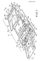
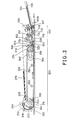
- Figs. 1-7 show a preferred embodiment of a document sheet feeder in accordance with the present invention applied to an automatic document feeder (to be referred to as "ADF" hereinafter in this specification).
- ADF automatic document feeder
- Reference numeral 10 designates an ADF main body mounted on a platen glass of a copying machine (not shown).
- the ADF main body 10 may be generally divided into a sheet feeding unit 100 and a sheet transportation unit 200.
- the sheet feeding unit 100 will be mainly described.
- the sheet feeding unit 100 has frames 102 and a document sheet stacker 106 upon which are stacked a plurality of sheets 104 is extended from the outer ends of the frames 102.
- An actuating level 107A of a feed sensor 107 is extended through hole 106A formed through the document sheet stacker 106.
- An inclined surface 108 is inclined at a predetermined angle between 25° and 35° and more preferably at 30° with respect to the document sheet stacker 106 and a separating plate 110 made of silicone rubber or the like is bonded over the inclined surface 108.
- Feed rollers 112 are carried by a rotating shaft 114 rotatably supported by the frames 102 and are made into contact with pinch rollers 116, respectively, which in turn are carried by a stationary shaft 118 at opposite ends thereof, respectively.
- the stationary shaft 118 is connected through swinging arms 120 to a driving shaft 122 rotatably supported by the frames 102.
- a cam follower 124 is carried by the driving shaft 122 at one end thereof (See Fig. 3).
- Separation rollers 130 to be described in more detail hereinafter are carried by a rotating shaft 134 whose both ends are rotatably supported by swinging arms 132, respectively.
- the end of each swinging arm 132 is rotatably mounted on the rotating shaft 114.
- the rotating shafts 114 and 134 carry pulleys 136 and 138, respectively, which are drivingly coupled to each other through an endless driving belt 140.
- a guide 133 with an elongated slot is defined at the upper surface of each swinging arm 132 and a driving rod 142 is extended through the elongated slots of the guides 133.
- One end of the driving rod 142 is attached to one end of a guide arm 146 which in turn is rotatably supported by the frame 102 with a pin 144 while the other end of the driving rod 142 is securely attached to one end of a driving arm 150 whose mid-point is rotatably supported by the frame 102 with a pin 148.
- the other end of the driving arm 150 terminates into a cam follower 151.
- One end of a supporting shaft 152 which is rotatably supported by the frames 102 carries a first cam 154 for engagement with the cam follower 151 while the other end of the supporting shaft 152 carries a second cam 156 for engagement with the cam follower 124, a gear 158 and a spring clutch 160.
- a rotating shaft of a feed motor 162 is drivingly connected through an endless driving belt 164 to a pulley 166 carried by one end of the rotating shaft 114 and to a gear 168 in mesh with the gear 158.
- the spring clutch 160 is engaged or disengaged in response to the forward or backward movement of a hook 172 driven by a first solenoid 170.
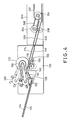
- An upper guide plate 174 and a lower guide plate 176 define a sheet feed passage (See Fig. 4).
- the separation roller 130 comprises a roller main body 130B having six equiangularly-spaced-apart grooves 130A, elastic blades 130C each in the form of a loop and wheel caps 130D attached to both ends of the roller main body 130B.
- a silicone rubber plate having ear portions 130E at opposite ends thereof as show in Fig. 5(A) is shaped in such a way that the ear portions 130E are superposed one on the other, thereby forming the loop-shaped portion 130F as shown in Fig. 5(B). Thereafter the superposed ear portions 130E are inserted into each of the grooves 130A of the roller main body 130B as shown in Fig. 5(C).
- Urethane rubber may be used to form the blades 130C, but the inventors found that the most preferable material is silicone rubber from the standpoint of low noise and separation and feeding capabilities.
- the sheet transportation unit 200 has frames 202 which may be formed integral with the frames 102 of the sheet feeding unit 100.
- Feed rollers 204 are carried by a rotating shaft 206 which in turn is rotatably supported by the frames 202 and pinch rollers 208 are adapted to be made into contact with their corresponding feed rollers 204.
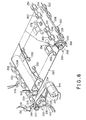
- One end of the rotating shaft 260 carries not only a spring clutch 210 but also a sprocket 212 and the spring clutch 210 is adapted to be engaged with a hook 216 driven by a second solenoid 214 (See Fig. 6).
- a sheet sensor 218 is adapted to detect the leading edge of a fed sheet 104.
- An upper guide plate 220 and a lower guide plate 222 define a sheet transportation passage (See Fig. 4). These guide plates 220 and 222 may be formed integral with the upper and lower guide plates 174 and 176 described above, respectively.
- a first belt roller 224 is carried by a driving shaft 226 which in turn is rotatably supported by the frames 202 and a second belt roller 228 is carried by a driven shaft 230 and the first and second belt rollers 224 and 228 are drivingly coupled to each other thorugh an endless transportation belt 232.
- One end of the driving shaft 226 carries a spring clutch 234 and sprockets 236 and 237 (which is not shown because it is behind the sprocket 236) and an encoder disk 238 having a plurality of slits equiangularly spaced apart from each other by a suitable angle.
- the encoder disk 238 is inserted into a space defined in a photointerruptor 240 so that a light beam is intermittently interrupted.
- a third solenoid 242 is adapted to cause a hook 239 to engage with the spring clutch 234.
- a transportation motor 244 has its driving shaft coupled drivingly to the sprocket 236 through an endless driving belt 246 and the sprocket 212 is driven through a driving belt 248 and the sprocket 237.
- Pressure rollers 250 are adapted to press the feed belt 232 against a platen glass of a copying machine (not shown).
- Discharge rollers 252 and 254 are carried by rotating shafts 256 and 258, respectively, which in turn are rotatably supported by the frames 202. Pinch rollers 260 and 262 are made into contact with their corresponding discharge rollers 252 and 254, respectively.
- One end of the rotating shaft 256 carries a sprocket 264 and one end of the rotating shaft 258 carries a sprocket 266. These sprockets 256 and 266 are driven through an endless transmission belt 270 by a sprocket 268 carried by one end of the driven shaft 230.
- Curved guide plates 272 and 274 are adapted to reverse the discharged sheet so as to guide it into a discharge tray 276 (See Fig. 2).
- a discharge sensor 278 is provided in order to detect the discharge of each sheet.
- Fig. 7 illustrates a block diagram of a control circuit for carrying out the sequence control when the document sheet feeder in accordance with the present invention is applied to an ADF. Signals are exchanged between a conventional one-chip microcomputer incorporating therein ROMs, RAMs and so on and a controller of a copying machine main body whose major component parts are input and output buffers in order to carry out the sequential control.
- the signals from the feed sensor 107, the sheet sensor 218 and the discharge sensor 218 and a copy operation start signal which is a command for activating this ADF as well as a document replacement demand signal for demanding the replacement of a sheet from a copying machine main body are applied to input ports I1 - I5, respectively, of the microcomputer.
- a signal from the photointerruptor 240 is applied to an offering (interruption) terminal INT and which represents a rotational speed of the first belt roller 224; that is, a reference clock for a quantity of a sheet to be transported and is counted by a counter incorporated within the microcomputer.
- energizing or de-energizing signals for energizing or de-energizing the first solenoid 170 for moving upwardly or downwardly the separation rollers 130 and the pinch rollers 116, the second solenoid 214 for starting or stopping the rotation of the feed rollers 204, the third solenoid 242 for starting or stopping the rotation of the first belt roller 224, the feed motor 162 and the transportation motor 244 through drivers D1 - D5, respectively.
- the read-in of these input signals or the output to each load is controlled by a program stored in the ROM incorporated in the microcomputer.
- the driving arm 150 Upon one half rotation of the first cam 154 engaged with the cam follower 151, the driving arm 150 is caused to rotate about the pin 148 so that the driving rod 142 forces the swinging arms 132 downwardly, whereby as shown in Fig. 4 the separation rollers 130 are forced to move downwardly.
- the pinch rollers 116 are forced to move upwardly so as to make into contact with the feed rollers 112 through the cam follower 124, the driving shaft 122 and the swinging arms 120.
- the first solenoid 170 is de-energized so that the hook 172 is caused to engage with the spring clutch 160 and consequently the transmission of power from the gear 158 to the supporting shaft 152 is interrupted.
- the rotation of the first and second cams 154 and 156 is stopped.
- the separation rollers 130 are driven through the rotating shaft 114 and the endless driving belt 140 by the feed motor 162 so that the uppermost sheet of the stack of sheets on the stacker 106 is forced to move toward the inclined surface 108 by frictional forces of the blades 130C each in the form of a loop.
- the loop-shaped blades 130C are made abruptly into contact with the uppermost sheet, but unlike the semi-cylindrical blades, the leading edge of each blade 130C is maintained in the form of a loop so that even when the loop-shaped blades 130C are made abruptly into contact with the uppermost sheet, no vibration occurs and the impact noise can be suppressed.
- each separation roller 130 has six blades 130C so that at least one of them is always made into contact with the sheet 104 so that the vertical vibration of the separation rollers 130 can be reduced.
- each separation roller may have four loop-shaped blades.
- each separation roller may have eight loop-shaped blades.
- each loop-shaped blade 130C is caused to deflect and deform in the direction opposite to the direction of the rotation of each separation roller as best shown in Fig. 4.
- the surface of contact of each loop-shaped blade 130C with the sheet 104 is increased in area and furthermore due to the elastic deformation of the loop-shaped blade 130C, the frictional force is increased so that the slip between the separation rollers 130 and the sheet 104 can be prevented.
- the leading edge of the sheet 104 reaches the inclined surface 108. While a leading portion of the sheet 104 is supported by the inclined surface 108 and the document sheet stacker 106, the center portion of the leading portion of the sheet 104 is pressed downwardly by the loop-shaped blades 130C so that the sheet 104 is deflected downwardly into a concave state. Therefore the separation of the uppermost sheet 104 can be positively carried out by the so-called "skillful manipulation".
- each separation roller 130 is located within a plane which includes the joint between the inclined surface 108 and the document sheet stacker 106 perpendicular to the upper surface of the document sheet stacker 106 or adjacent the plane. Furthermore according to the present embodiment, the separation plate 110 made of silicone rubber is bonded over the inclined surface 108 so that the positive separation is ensured.
- the angle ⁇ which can attain satisfactory separation and feed capabilities is between 25° and 35° and more preferably 30°.
- the sheet thus separated is further bent when its leading edge is made into contact with the guide plate 174 and is clamped between the feed rollers 112 and the pinch rollers 116 and fed.
- the transportation motor 244 is energized concurrently with the output of the copy start signal.
- the second solenoid 214 is energized to engage the spring clutch 210 by the hook 216 so that the feed rollers 204 and the pinch rollers 208 are rotated to wait for the supply of a sheet.
- the first solenoid 170 is energized to operate the spring clutch 160 so that the first and second cams 154 and 156 are rotated by one half of rotation again. Consequently the separation rollers 130 are moved upwardly while the pinch rollers 116 are moved downwardly, whereby the separation and feed of the sheet are interrupted. The above-described state is maintained until the generation of a document replacement demand signal.
- the second solenoid 214 is de-energized to disengage the spring clutch 210 so that the feed rollers 204 and the pinch rollers 208 are stopped to hold the sheet.
- the second and third solenoids 214 and 242 are concurrently energized so that the hooks 216 and 239 are moved upwardly, whereby the spring clutches 210 and 234 are engaged.
- the transportation motor 244 rotates the feed rollers 204, the pinch rollers 208 and the first belt roller 224.
- the amount of the feed of the sheet by the transporation belt 232 is obtained by the number of rotations of the encoder disk 238 which in turn is converted into the number of pulses delivered from the photointerruptor 240 and the number of pulses is counted by a counter incorporated in the microcomputer.
- the third solenoid 242 is de-energized to disengage the spring clutch 234 so that the rotation of the first belt roller 224 and thus the driving of the transporation belt 232 are interrupted.
- the rotation of the feed rollers 204 continues to wait for the feed of the next sheet.
- the feed rollers 204 are stopped so that the sheet remains in the waiting state.
- the separation rollers 130 are moved upwardly while the pinch rollers 116 are moved downwardly concurrently and then the feed motor 162 is de-energized.
- the transportation motor is de-energized.
- each separated sheet is fed to and temporarily remains at the waiting position so that while the preceding sheet is being copied, the pre-handling of the succeeding sheet has been accomplished.
- the practical processing time can be shortened.
- the document sheet feeder in accordance with the present invention can be simplified in construction and manufactured at less costs.
Landscapes
- Engineering & Computer Science (AREA)
- Mechanical Engineering (AREA)
- Sheets, Magazines, And Separation Thereof (AREA)
- Conveyance By Endless Belt Conveyors (AREA)
Applications Claiming Priority (2)
| Application Number | Priority Date | Filing Date | Title |
|---|---|---|---|
| JP63152408A JPH028124A (ja) | 1988-06-22 | 1988-06-22 | 原稿給送装置 |
| JP152408/88 | 1988-06-22 |
Publications (2)
| Publication Number | Publication Date |
|---|---|
| EP0347889A2 true EP0347889A2 (fr) | 1989-12-27 |
| EP0347889A3 EP0347889A3 (fr) | 1990-11-28 |
Family
ID=15539859
Family Applications (1)
| Application Number | Title | Priority Date | Filing Date |
|---|---|---|---|
| EP19890111320 Withdrawn EP0347889A3 (fr) | 1988-06-22 | 1989-06-21 | Dispositif d'alimentation en feuilles |
Country Status (3)
| Country | Link |
|---|---|
| US (1) | US5120042A (fr) |
| EP (1) | EP0347889A3 (fr) |
| JP (1) | JPH028124A (fr) |
Cited By (6)
| Publication number | Priority date | Publication date | Assignee | Title |
|---|---|---|---|---|
| US5244294A (en) * | 1992-06-29 | 1993-09-14 | Apple Computer, Inc. | Apparatus for transporting wet print media and method for same |
| GB2307900A (en) * | 1995-12-05 | 1997-06-11 | Ferag Ag | Roller mounted spring for sheet acceleration or deceleration |
| US6267369B1 (en) * | 1999-07-02 | 2001-07-31 | Hewlett-Packard Company | Torque loading of a sheet material feed roller |
| EP1634830A3 (fr) * | 2004-09-14 | 2006-03-22 | Fuji Photo Film Co., Ltd. | Unité d'alimentation pour plaques d'impression lithographique |
| EP0780816B1 (fr) * | 1995-12-22 | 2014-08-06 | NCR International, Inc. | Dispositif pour détecter la présence et la vitesse d'un moyen d'enregistrement |
| CN108100706A (zh) * | 2016-11-24 | 2018-06-01 | 兄弟工业株式会社 | 片状物传送器和图像形成设备 |
Families Citing this family (19)
| Publication number | Priority date | Publication date | Assignee | Title |
|---|---|---|---|---|
| JP2963723B2 (ja) * | 1990-04-20 | 1999-10-18 | キヤノン株式会社 | カットシート分離装置 |
| JPH0434241U (fr) * | 1990-07-19 | 1992-03-23 | ||
| IT1250451B (it) * | 1991-07-03 | 1995-04-07 | Minnesota Mining & Mfg | Dispositivo per alimentare un singolo foglio di film da una pila di fogli di film. |
| DE69227551T2 (de) * | 1991-08-21 | 1999-05-27 | Canon K.K., Tokio/Tokyo | Automatischer Apparat zum Zuführen von Blättern |
| DE4309473A1 (de) * | 1992-03-24 | 1993-09-30 | Asahi Optical Co Ltd | Elektrofotografisches Gerät |
| DE69307410T2 (de) * | 1992-06-30 | 1997-05-22 | Canon Kk | Automatische Blattzufuhreinrichtung |
| JPH0750739A (ja) * | 1993-06-15 | 1995-02-21 | Gold Star Co Ltd | ファクシミリの多枚給紙装置 |
| US6135444A (en) * | 1998-12-15 | 2000-10-24 | Hewlett-Packard Company | Automatic sheet feeding mechanism |
| US6382619B1 (en) | 2000-04-19 | 2002-05-07 | Hewlett-Packard Company | Pick mechanism and image forming device including the same |
| JP3653611B2 (ja) | 2000-05-18 | 2005-06-02 | 光洋精工株式会社 | 電動式舵取装置 |
| AU2001282581A1 (en) * | 2000-09-01 | 2002-03-13 | Showa Denko K K | Apparatus for producing capacitor element member |
| US6764072B2 (en) * | 2001-06-13 | 2004-07-20 | Hewlett-Packard Development Company, L.P. | Sheet feeder roller assembly with stack damper |
| JP4072397B2 (ja) * | 2002-08-16 | 2008-04-09 | キヤノン株式会社 | 自動給送装置及びそれを備えた記録装置 |
| CN100368207C (zh) * | 2002-08-20 | 2008-02-13 | 夏普株式会社 | 送纸装置以及具有该送纸装置的图像形成装置 |
| US7303188B2 (en) * | 2003-11-06 | 2007-12-04 | James Malatesta | Document separator |
| US7533878B2 (en) * | 2004-06-10 | 2009-05-19 | Lexmark International, Inc. | Printer media transport for variable length media |
| JP4160086B2 (ja) * | 2006-05-09 | 2008-10-01 | シャープ株式会社 | 原稿搬送装置及びそれを用いた画像読取り装置 |
| JP2010030769A (ja) * | 2008-07-30 | 2010-02-12 | Seiko Epson Corp | 給送装置及び記録装置 |
| JP4645718B2 (ja) * | 2008-09-29 | 2011-03-09 | ブラザー工業株式会社 | 画像記録装置 |
Family Cites Families (11)
| Publication number | Priority date | Publication date | Assignee | Title |
|---|---|---|---|---|
| DE481988C (de) * | 1929-09-05 | Gerald Strecker Dipl Ing | Foerderpresse fuer Querschneider | |
| US3630516A (en) * | 1970-03-23 | 1971-12-28 | Stromberg Datagraphix Inc | Sheet-feeding apparatus |
| US3649003A (en) * | 1970-06-29 | 1972-03-14 | Baeuerle Gmbh Mathias | Sheet feeding mechanism for a small duplicating machine |
| BE791064A (fr) * | 1971-11-08 | 1973-05-08 | Xerox Corp | Appareil d'avancement de feuilles |
| US4192497A (en) * | 1974-04-26 | 1980-03-11 | Xerox Corporation | Composition for the surface of sheet separating devices |
| JPS5240142U (fr) * | 1975-09-12 | 1977-03-22 | ||
| DE2650564B1 (de) * | 1976-11-04 | 1978-02-16 | Nixdorf Comp Ag | Vorrichtung zum Vereinzeln von Belegen,Karten u.dgl.,insbesondere von Geldscheinen |
| US4394009A (en) * | 1980-11-06 | 1983-07-19 | Standard Duplicating Machines Corporation | Sheet feeder with buckle restraint and feed roll slippage |
| US4566684A (en) * | 1984-01-12 | 1986-01-28 | National Computer Systems | Automatic sheet feed mechanism |
| JPH048112Y2 (fr) * | 1985-07-29 | 1992-03-02 | ||
| JPS6244611A (ja) * | 1985-08-23 | 1987-02-26 | Hitachi Ltd | 測定方法 |
-
1988
- 1988-06-22 JP JP63152408A patent/JPH028124A/ja active Pending
-
1989
- 1989-06-19 US US07/367,946 patent/US5120042A/en not_active Expired - Fee Related
- 1989-06-21 EP EP19890111320 patent/EP0347889A3/fr not_active Withdrawn
Cited By (8)
| Publication number | Priority date | Publication date | Assignee | Title |
|---|---|---|---|---|
| US5244294A (en) * | 1992-06-29 | 1993-09-14 | Apple Computer, Inc. | Apparatus for transporting wet print media and method for same |
| GB2307900A (en) * | 1995-12-05 | 1997-06-11 | Ferag Ag | Roller mounted spring for sheet acceleration or deceleration |
| GB2307900B (en) * | 1995-12-05 | 2000-06-07 | Ferag Ag | Method and device for decelerating or accelerating and/or for deflecting conveyed printed products |
| EP0780816B1 (fr) * | 1995-12-22 | 2014-08-06 | NCR International, Inc. | Dispositif pour détecter la présence et la vitesse d'un moyen d'enregistrement |
| US6267369B1 (en) * | 1999-07-02 | 2001-07-31 | Hewlett-Packard Company | Torque loading of a sheet material feed roller |
| EP1634830A3 (fr) * | 2004-09-14 | 2006-03-22 | Fuji Photo Film Co., Ltd. | Unité d'alimentation pour plaques d'impression lithographique |
| US7222570B2 (en) | 2004-09-14 | 2007-05-29 | Fujifilm Corporation | Planographic printing plate supply unit including carrying roller with hollow convex portions |
| CN108100706A (zh) * | 2016-11-24 | 2018-06-01 | 兄弟工业株式会社 | 片状物传送器和图像形成设备 |
Also Published As
| Publication number | Publication date |
|---|---|
| EP0347889A3 (fr) | 1990-11-28 |
| US5120042A (en) | 1992-06-09 |
| JPH028124A (ja) | 1990-01-11 |
Similar Documents
| Publication | Publication Date | Title |
|---|---|---|
| US5120042A (en) | Document sheet feeder | |
| EP0137381B1 (fr) | Dispositif d'alimentation en papier | |
| US6199855B1 (en) | Paper feeding apparatus for office automation system | |
| EP0349013A1 (fr) | Dispositif d'avancement du papier | |
| EP0376520B2 (fr) | Alimentateur à butée frontale pour une machine à manipuler le courrier | |
| JP2651602B2 (ja) | 給紙装置 | |
| US5680203A (en) | Image processor having a document conveyor with document suppressing rollers and a document suppressing plate, providing a uniform space for document passage | |
| CN110320766A (zh) | 图像读取装置 | |
| US5601281A (en) | Automatic document feeding device | |
| CN110329829B (zh) | 图像读取装置 | |
| EP0657296B1 (fr) | Dispositif d'alimentation en papier | |
| EP0333140A1 (fr) | Dispositif d'alimentation automatique de documents | |
| EP0279642B1 (fr) | Dispositif d'alimentation en papier pour imprimante | |
| KR0124607B1 (ko) | 팩시밀리의 다매급지장치 | |
| US5295676A (en) | Sheet feeding apparatus | |
| US4962920A (en) | Sheet sorting device | |
| US5332205A (en) | Automatic document feeders for copying machines and method for automatically controlling such | |
| EP0764602A2 (fr) | Appareil séparateur de feuilles | |
| US7837189B2 (en) | Elastomer gripping belt loop for a disc stacker system | |
| US4750727A (en) | Automatic document feeder for copiers | |
| JPH06227683A (ja) | 給紙用底板の上昇装置 | |
| JPH0729071Y2 (ja) | 給紙装置のガイド板保持構造 | |
| JP2630435B2 (ja) | 給紙装置 | |
| JP3368667B2 (ja) | 原稿給紙装置 | |
| KR930002998Y1 (ko) | 복사기의 자동급지장치 |
Legal Events
| Date | Code | Title | Description |
|---|---|---|---|
| PUAI | Public reference made under article 153(3) epc to a published international application that has entered the european phase |
Free format text: ORIGINAL CODE: 0009012 |
|
| 17P | Request for examination filed |
Effective date: 19890621 |
|
| AK | Designated contracting states |
Kind code of ref document: A2 Designated state(s): DE FR GB |
|
| PUAL | Search report despatched |
Free format text: ORIGINAL CODE: 0009013 |
|
| AK | Designated contracting states |
Kind code of ref document: A3 Designated state(s): DE FR GB |
|
| 17Q | First examination report despatched |
Effective date: 19921214 |
|
| STAA | Information on the status of an ep patent application or granted ep patent |
Free format text: STATUS: THE APPLICATION IS DEEMED TO BE WITHDRAWN |
|
| 18D | Application deemed to be withdrawn |
Effective date: 19931228 |