EP0347896A1 - Anneau pour des métiers à filer - Google Patents
Anneau pour des métiers à filer Download PDFInfo
- Publication number
- EP0347896A1 EP0347896A1 EP89111339A EP89111339A EP0347896A1 EP 0347896 A1 EP0347896 A1 EP 0347896A1 EP 89111339 A EP89111339 A EP 89111339A EP 89111339 A EP89111339 A EP 89111339A EP 0347896 A1 EP0347896 A1 EP 0347896A1
- Authority
- EP
- European Patent Office
- Prior art keywords
- ring
- plated layer
- traveller
- hard fine
- fine particles
- Prior art date
- Legal status (The legal status is an assumption and is not a legal conclusion. Google has not performed a legal analysis and makes no representation as to the accuracy of the status listed.)
- Granted
Links
Images


Classifications
-
- D—TEXTILES; PAPER
- D01—NATURAL OR MAN-MADE THREADS OR FIBRES; SPINNING
- D01H—SPINNING OR TWISTING
- D01H7/00—Spinning or twisting arrangements
- D01H7/02—Spinning or twisting arrangements for imparting permanent twist
- D01H7/52—Ring-and-traveller arrangements
- D01H7/60—Rings or travellers; Manufacture thereof not otherwise provided for ; Cleaning means for rings
-
- D—TEXTILES; PAPER
- D01—NATURAL OR MAN-MADE THREADS OR FIBRES; SPINNING
- D01H—SPINNING OR TWISTING
- D01H7/00—Spinning or twisting arrangements
- D01H7/02—Spinning or twisting arrangements for imparting permanent twist
- D01H7/52—Ring-and-traveller arrangements
- D01H7/60—Rings or travellers; Manufacture thereof not otherwise provided for ; Cleaning means for rings
- D01H7/602—Rings
Definitions
- the present invention relates to a ring for spinning machineries, used in the fine spinning of spinning work, and exhibiting excellent characteristics especially in high speed fine spinning.
- low carbon steel is used in a ring for spinning machinery, and carburizing hardening treatment is applied thereon as a case hardening treatment.
- the spindle of a fine spinning machine is used at high speed revolution of 20,000 r.p.m. or more, there has been such a problem that the friction resistance between the ring and the traveller increases, and the frictional heat rapidly increases to bring about the baking and blow off the traveller in an early period, to make continuous operation impossible.
- the object of the present invention is to improve the anti-wearing properties of the ring and its baking resistance against the traveller, by crystallizing the nickel alloy plated on the ring surface as the matrix of the composite plated layer. According to this invention, plated layer hardness is tremendously enhanced and, at the same time, the adhering force of hard fine grains to the nickel alloy as the matrix is strengthened.
- Another object of the present invention is to improve the sliding properties of the traveller by exposing hard fine grains 5 to 40 % in an area percentage on the surface of the ring which the traveller contacts to and and slides on, and by making the surface roughness less than Ra 0.2 ⁇ m.
- the present inventors have carried out researches in connection with plating and surface finishing to be applied to the ring surface. As a result, the present invention has been achieved.
- a steel material (S15 CK) of cylindrical shape was cut and processed to form a ring 1 (Fig. 1), and the ring was subjected to carburizing hardening and surface treatment.
- the above-described ring had such a structure that it had a collar 3 on the external circumferential surface of the cylindrically shaped trunk part, and further, had a ring flange 5 on which the ring traveller slides, at the top of the ring neck part 4.
- the above-described ring 1 was, after being subjected to the pre-treatment of the plating such as degreasing and acid cleaning on at least the surface of the ring flange 5, was covered by forming a composite plated layer 6 dispersed and separated with silicon carbide as a co-separating substance in the matrix of a nickel-phosphorous alloy 7. (Fig. 2)
- the composite plated layer 6 was formed by electroless plating with the dispersion of the silicon carbide 8 of a particle size of 1 ⁇ m as hard fine grains in such an amount that its content becomes approximately 4 % by weight, in the matrix of the nickel-phosphorous alloy 7.
- the ring 1 on which the composite plated layer 6 was formed was subjected to heat treatment in a heat treating furnace at the heat treating temperature of 400 °C for about 1 hour to crystallize the nickel-phosphorous of the matrix. Due to this crystallization, the composite plated layer could obtain the high hardness of HV 1000. Moreover, the closely adhering properties of the co-separating substance, silicon carbide, to the matrix was strengthened.
- the ring flange 5 to which the ring traveller of the ring 1 subjected to heat treatment contacts and slides was formed by subjecting it to the polish processing by use of lapping to be formed to have the thickness of the composite plated layer of 30 ⁇ m.
- polish processing By carrying out polish processing, hard fine grains were exposed on the surface of the ring flange 5, and the flange was finished to become a smooth surface with the surface roughness off less than 0.2 ⁇ m.
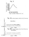
- Figs. 4a and 4b shown are the data of the surface roughness before and after the polishing process. Also, in Fig. 5a, the surface state of the ring flange 5 before the polishing process is shown, and in Fig. 5b, the surface state of the ring flange after the polishing process is shown.
- the most outside surface of the composite plated layer 6 shows the co-existance state of the hard fine particles of the silicon carbide 8 exposed in the matrix, nickel-phosphorous alloy 7.
- the most preferable substance as the hard fine particles which is co-separated in the composite plated layer 6, is silicon carbide 8 having high hardness, large anti-chemical properties and anti-wearing properties, and good thermal conductivity.
- the ring 1 on which the above-described composite plated layer 6 is formed has such an advantage that it easily radiates the friction heat gererated in the time when the ring traveller runs on the ring flange, and elongates the life of the traveller.
- the hard fine particles Although silicon carbide has been used as the hard fine particles, at least one kind or two or more kinds of tungsten carbide, boron nitride, or aluminium oxide can be also used.
- the particle diameter of the hard fine particles is preferably in the range of 0.2 ⁇ m to 3 ⁇ m, and when it is less than 0.2 ⁇ m, the anti-wearing properties of the ring are inferior, and when it exceeds 3 ⁇ m, hard fine particles drop out from the composite plated layer, and the radiation of the friction heat becomes bad, to shorten the life of the traveller, and together with that, to lower the anti-wearing properties of the ring remarkably.
- the content percentage of the hard fine particles included in the matrix of the composite plated layer is 2 to 15 % by weight.
- the area percentage of the particles in the surface and in the cross section of the ring flange is observed to be 5 to 40 % preferably 10 to 30 %.
- the area percentage of the silicon carbide described in the above-described embodiment was 19.5 % in the cross section, and 25.6 % in the surface.
- the area percentage of the silicon carbide is less than 5 %, the anti-wearing property of the ring deteriorates, and when it exceeds 40 % the sliding property of the ring traveller deteriorates to cause the baking of the traveller at an early time and frequent yarn cuttings.
- the thickness of the composite plated layer 6 was taken as 30 ⁇ m, the thickness of 5 to 35 ⁇ m is preferable, and when it is less than 5 ⁇ m, the anti-wearing properties at the spindle revolution of more than 20,000 r.p.m. deteriorate , and when it exceeds 35 ⁇ m, the treating time of the composite plating becomes extremely long to make the production cost of the ring high.
- the thickness of the composite plated layer is taken as 16 to 35 ⁇ m, since the life in the high speed spinning can be prolonged.
- the heat treatment conditions of the ring 1 formed with the composite plated layer 6 were such that the heat treatment time at the heat treatment temperature of 400 °C was about 1 hour, but the heat treatment may be effected at the heat treatment temperature of 320 to 420 °C and for the heat treatment time of about 1 to 2 hours.
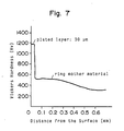
- the hardness of the mother material immediately below the composite plated layer is preferably at Hv 500 to 650.
- the suface of the ring on which the ring traveller contacts and slides was polish processed to make the surface roughness of the surface of the ring becomes less than Ra 0.2 ⁇ m.
- the surface roughness of the composite plating exceeds 0.2 ⁇ m in Ra, the running of the ring traveller is disturbed, and high speed operation becomes unable to be carried out.
- the surface roughness be less than Ra 0.2 ⁇ m, not only the running of the ring traveller was made smooth, but also the friction resistance of the ring traveller in the high speed revolution zone of the spindle revolution was reduced, since it made the hard fine particles having high hardness and excellent anti-wearing properties be exposed on the most external surface of the composite plated layer to form the coexistence state with the matrix.
- nickel-phosphorous alloy nickel-tungsten-phosphorous alloy, and the like are used.
- Comparative test was carried out by using the ring (A) for spinning machine of the present invention, the ring (B) for spinning machine obtained by effecting case hardening carburizing hardening to the conventional low carbon steel, and the conventional ring (C) which was subjected to the above described composite plating and having the surface roughness of Ra 0.4 ⁇ m.
- Fig. 6 are shown the friction resistance indices of the ring traveller and the ring at the revolution number of each spindle under the above-described spinning conditions.
- a composite plated layer is formed by making hard fine particles as a co-separating substance and the nickel-phosphorous containing nickel alloy as a matrix, and the hardness of the matrix is made be Hv 900 to 1200, and hard fine particles are exposed on the surface thereof, and the surface roughness is made be less than Ra 0.2 ⁇ m, so that the ring traveller shows good fit even in the super high speed revolution zone of the spindle revolution of more than 24,000 r.p.m., and stabilized continuous operation can be carried out. Moreover the baking of the ring traveller is prolonged.
- the peel out of the composite plated layer does not occur, and the performance of the ring can be maintained for a long period.
- the hardness of the ring mother material immediately below the composite plated layer is made as Hv 500 to 650, there is such excellent effects that the wear amount of the ring is little, the life of the ring is prolonged, and the like.
Landscapes
- Engineering & Computer Science (AREA)
- Mechanical Engineering (AREA)
- Textile Engineering (AREA)
- Spinning Or Twisting Of Yarns (AREA)
Applications Claiming Priority (2)
| Application Number | Priority Date | Filing Date | Title |
|---|---|---|---|
| JP63155445A JPH01321925A (ja) | 1988-06-23 | 1988-06-23 | 紡機用リング |
| JP155445/88 | 1988-06-23 |
Publications (2)
| Publication Number | Publication Date |
|---|---|
| EP0347896A1 true EP0347896A1 (fr) | 1989-12-27 |
| EP0347896B1 EP0347896B1 (fr) | 1997-11-26 |
Family
ID=15606195
Family Applications (1)
| Application Number | Title | Priority Date | Filing Date |
|---|---|---|---|
| EP89111339A Expired - Lifetime EP0347896B1 (fr) | 1988-06-23 | 1989-06-22 | Anneau pour des métiers à filer |
Country Status (4)
| Country | Link |
|---|---|
| EP (1) | EP0347896B1 (fr) |
| JP (1) | JPH01321925A (fr) |
| KR (1) | KR960016472B1 (fr) |
| DE (1) | DE68928458T2 (fr) |
Cited By (3)
| Publication number | Priority date | Publication date | Assignee | Title |
|---|---|---|---|---|
| DE4335539A1 (de) * | 1992-11-04 | 1994-05-05 | Rieter Ag Maschf | Spinnring mit Metall-Phosphor-Beschichtung |
| DE4335538A1 (de) * | 1992-11-04 | 1994-05-05 | Rieter Ag Maschf | Spinnring mit Verschleiß-Schutzschicht und Einlaufschicht |
| RU2130518C1 (ru) * | 1993-12-10 | 1999-05-20 | Церазив ГмбХ Инновативес Керамик-Инджиниринг | Система кольцо-бегунок к прядильным и крутильным машинам и способ обработки поверхности кольца в системе кольцо-бегунок к прядильным и крутильным машинам |
Families Citing this family (1)
| Publication number | Priority date | Publication date | Assignee | Title |
|---|---|---|---|---|
| US5175988A (en) * | 1988-06-23 | 1993-01-05 | Kanai Juyo Kogyo Company Ltd. | Ring for spinning machinery |
Citations (2)
| Publication number | Priority date | Publication date | Assignee | Title |
|---|---|---|---|---|
| DE3026210A1 (de) * | 1980-07-10 | 1982-02-11 | Hollingsworth Gmbh, 7265 Neubulach | Verfahren zum erhoehen der verschleissfestigkeit des saegezahndrahtbeschlages der trommel einer karde |
| US4698958A (en) * | 1984-09-27 | 1987-10-13 | Kanai Juyo Kogyo Co., Ltd. | Ring for spinning and twisting machines |
-
1988
- 1988-06-23 JP JP63155445A patent/JPH01321925A/ja active Granted
-
1989
- 1989-06-22 EP EP89111339A patent/EP0347896B1/fr not_active Expired - Lifetime
- 1989-06-22 DE DE68928458T patent/DE68928458T2/de not_active Expired - Fee Related
- 1989-06-22 KR KR1019890008647A patent/KR960016472B1/ko not_active Expired - Fee Related
Patent Citations (2)
| Publication number | Priority date | Publication date | Assignee | Title |
|---|---|---|---|---|
| DE3026210A1 (de) * | 1980-07-10 | 1982-02-11 | Hollingsworth Gmbh, 7265 Neubulach | Verfahren zum erhoehen der verschleissfestigkeit des saegezahndrahtbeschlages der trommel einer karde |
| US4698958A (en) * | 1984-09-27 | 1987-10-13 | Kanai Juyo Kogyo Co., Ltd. | Ring for spinning and twisting machines |
Non-Patent Citations (2)
| Title |
|---|
| PATENT ABSTRACTS OF JAPAN vol. 11, no. 89 (C-411)(2536) 19 March 1987, & JP-A-61 245320 (HIROYUKI KANAI) * |
| PATENT ABSTRACTS OF JAPAN vol. 12, no. 5 (C-467)(2852) 08 January 1988, & JP-A-62 161995 (HIROYUKI KANAI) * |
Cited By (3)
| Publication number | Priority date | Publication date | Assignee | Title |
|---|---|---|---|---|
| DE4335539A1 (de) * | 1992-11-04 | 1994-05-05 | Rieter Ag Maschf | Spinnring mit Metall-Phosphor-Beschichtung |
| DE4335538A1 (de) * | 1992-11-04 | 1994-05-05 | Rieter Ag Maschf | Spinnring mit Verschleiß-Schutzschicht und Einlaufschicht |
| RU2130518C1 (ru) * | 1993-12-10 | 1999-05-20 | Церазив ГмбХ Инновативес Керамик-Инджиниринг | Система кольцо-бегунок к прядильным и крутильным машинам и способ обработки поверхности кольца в системе кольцо-бегунок к прядильным и крутильным машинам |
Also Published As
| Publication number | Publication date |
|---|---|
| EP0347896B1 (fr) | 1997-11-26 |
| KR900000497A (ko) | 1990-01-30 |
| KR960016472B1 (ko) | 1996-12-12 |
| JPH01321925A (ja) | 1989-12-27 |
| JPH0571685B2 (fr) | 1993-10-07 |
| DE68928458T2 (de) | 1998-05-07 |
| DE68928458D1 (de) | 1998-01-08 |
Similar Documents
| Publication | Publication Date | Title |
|---|---|---|
| EP0201602B1 (fr) | Anneau pour machines a filer | |
| US4928477A (en) | Process for forming a fiber or yarn contacted element of a textile machine | |
| US3343362A (en) | Bearing members having a plurality of coatings | |
| EP0347896B1 (fr) | Anneau pour des métiers à filer | |
| US5175988A (en) | Ring for spinning machinery | |
| EP0282440B1 (fr) | Meule obtenue par électrodéposition | |
| JP2632723B2 (ja) | 紡機用リング | |
| US5702763A (en) | Selective codeposition of particulate matter and composite plated articles thereof | |
| JP2750608B2 (ja) | 紡機用リング | |
| JPS63282295A (ja) | 耐摩耗表面層 | |
| US5674631A (en) | Selective codeposition of particulate matter and composite plated articles thereof | |
| JPS6138000A (ja) | 紡機用トラベラ | |
| JPH0625898A (ja) | 摺動部材 | |
| JPH05106124A (ja) | 紡機用リング | |
| JP2873354B2 (ja) | 紡機用リング | |
| KR920007628Y1 (ko) | 방적기용 트레블러 | |
| JP2627343B2 (ja) | 紡機用トラベラ | |
| JPH05106125A (ja) | 紡機用金属トラベラ | |
| JP2526058B2 (ja) | 紡機用トラベラ | |
| JPH0192432A (ja) | 紡機用金属トラベラ | |
| JPH04194031A (ja) | 紡機用リング | |
| JPH05117927A (ja) | 紡機用リング | |
| JP2536001Y2 (ja) | 紡機用リング | |
| JPH03199434A (ja) | 紡機用リング | |
| JPH03193933A (ja) | 紡機用リング |
Legal Events
| Date | Code | Title | Description |
|---|---|---|---|
| PUAI | Public reference made under article 153(3) epc to a published international application that has entered the european phase |
Free format text: ORIGINAL CODE: 0009012 |
|
| AK | Designated contracting states |
Kind code of ref document: A1 Designated state(s): CH DE IT LI |
|
| 17P | Request for examination filed |
Effective date: 19900525 |
|
| 17Q | First examination report despatched |
Effective date: 19920212 |
|
| GRAG | Despatch of communication of intention to grant |
Free format text: ORIGINAL CODE: EPIDOS AGRA |
|
| GRAH | Despatch of communication of intention to grant a patent |
Free format text: ORIGINAL CODE: EPIDOS IGRA |
|
| GRAH | Despatch of communication of intention to grant a patent |
Free format text: ORIGINAL CODE: EPIDOS IGRA |
|
| GRAA | (expected) grant |
Free format text: ORIGINAL CODE: 0009210 |
|
| AK | Designated contracting states |
Kind code of ref document: B1 Designated state(s): CH DE IT LI |
|
| REG | Reference to a national code |
Ref country code: CH Ref legal event code: EP |
|
| REF | Corresponds to: |
Ref document number: 68928458 Country of ref document: DE Date of ref document: 19980108 |
|
| ITF | It: translation for a ep patent filed | ||
| REG | Reference to a national code |
Ref country code: CH Ref legal event code: NV Representative=s name: BOVARD AG PATENTANWAELTE |
|
| PLBE | No opposition filed within time limit |
Free format text: ORIGINAL CODE: 0009261 |
|
| STAA | Information on the status of an ep patent application or granted ep patent |
Free format text: STATUS: NO OPPOSITION FILED WITHIN TIME LIMIT |
|
| 26N | No opposition filed | ||
| PGFP | Annual fee paid to national office [announced via postgrant information from national office to epo] |
Ref country code: IT Payment date: 20060630 Year of fee payment: 18 Ref country code: DE Payment date: 20060630 Year of fee payment: 18 Ref country code: CH Payment date: 20060630 Year of fee payment: 18 |
|
| REG | Reference to a national code |
Ref country code: CH Ref legal event code: PL |
|
| PG25 | Lapsed in a contracting state [announced via postgrant information from national office to epo] |
Ref country code: LI Free format text: LAPSE BECAUSE OF NON-PAYMENT OF DUE FEES Effective date: 20070630 Ref country code: DE Free format text: LAPSE BECAUSE OF NON-PAYMENT OF DUE FEES Effective date: 20080101 Ref country code: CH Free format text: LAPSE BECAUSE OF NON-PAYMENT OF DUE FEES Effective date: 20070630 |
|
| PG25 | Lapsed in a contracting state [announced via postgrant information from national office to epo] |
Ref country code: IT Free format text: LAPSE BECAUSE OF NON-PAYMENT OF DUE FEES Effective date: 20070622 |