EP0348242A2 - Kassetten-Lademechanismus - Google Patents
Kassetten-Lademechanismus Download PDFInfo
- Publication number
- EP0348242A2 EP0348242A2 EP89306430A EP89306430A EP0348242A2 EP 0348242 A2 EP0348242 A2 EP 0348242A2 EP 89306430 A EP89306430 A EP 89306430A EP 89306430 A EP89306430 A EP 89306430A EP 0348242 A2 EP0348242 A2 EP 0348242A2
- Authority
- EP
- European Patent Office
- Prior art keywords
- cassette
- lid
- size cassette
- engaging
- large size
- Prior art date
- Legal status (The legal status is an assumption and is not a legal conclusion. Google has not performed a legal analysis and makes no representation as to the accuracy of the status listed.)
- Granted
Links
Images

Classifications
-
- G—PHYSICS
- G11—INFORMATION STORAGE
- G11B—INFORMATION STORAGE BASED ON RELATIVE MOVEMENT BETWEEN RECORD CARRIER AND TRANSDUCER
- G11B15/00—Driving, starting or stopping record carriers of filamentary or web form; Driving both such record carriers and heads; Guiding such record carriers or containers therefor; Control thereof; Control of operating function
- G11B15/675—Guiding containers, e.g. loading, ejecting cassettes
-
- G—PHYSICS
- G11—INFORMATION STORAGE
- G11B—INFORMATION STORAGE BASED ON RELATIVE MOVEMENT BETWEEN RECORD CARRIER AND TRANSDUCER
- G11B15/00—Driving, starting or stopping record carriers of filamentary or web form; Driving both such record carriers and heads; Guiding such record carriers or containers therefor; Control thereof; Control of operating function
- G11B15/675—Guiding containers, e.g. loading, ejecting cassettes
- G11B15/67563—Guiding containers, e.g. loading, ejecting cassettes with movement of the cassette perpendicular to its main side, i.e. top loading
- G11B15/67565—Guiding containers, e.g. loading, ejecting cassettes with movement of the cassette perpendicular to its main side, i.e. top loading of the cassette with holder
-
- G—PHYSICS
- G11—INFORMATION STORAGE
- G11B—INFORMATION STORAGE BASED ON RELATIVE MOVEMENT BETWEEN RECORD CARRIER AND TRANSDUCER
- G11B15/00—Driving, starting or stopping record carriers of filamentary or web form; Driving both such record carriers and heads; Guiding such record carriers or containers therefor; Control thereof; Control of operating function
- G11B15/675—Guiding containers, e.g. loading, ejecting cassettes
- G11B15/67544—Guiding containers, e.g. loading, ejecting cassettes with movement of the cassette parallel to its main side and subsequent movement perpendicular thereto, i.e. front loading
- G11B15/67547—Guiding containers, e.g. loading, ejecting cassettes with movement of the cassette parallel to its main side and subsequent movement perpendicular thereto, i.e. front loading the two movements being made by the cassette holder
-
- G—PHYSICS
- G11—INFORMATION STORAGE
- G11B—INFORMATION STORAGE BASED ON RELATIVE MOVEMENT BETWEEN RECORD CARRIER AND TRANSDUCER
- G11B25/00—Apparatus characterised by the shape of record carrier employed but not specific to the method of recording or reproducing, e.g. dictating apparatus; Combinations of such apparatus
- G11B25/06—Apparatus characterised by the shape of record carrier employed but not specific to the method of recording or reproducing, e.g. dictating apparatus; Combinations of such apparatus using web-form record carriers, e.g. tape
- G11B25/066—Apparatus characterised by the shape of record carrier employed but not specific to the method of recording or reproducing, e.g. dictating apparatus; Combinations of such apparatus using web-form record carriers, e.g. tape adapted for use with containers of different sizes or configurations; adaptor devices therefor
Definitions
- This invention relates to a cassette loading mechanism for a recording/reproducing device for loading a cassette enclosing a magnetic tape to a recoding/reproducing position.
- This invention also is utilized in the cassette loading mechanism in which plural kinds of cassettes having different sizes can be selectively attached in the device for recording and/or reproduction.
- cassettes of different sizes for enclosing a magnetic tape as the magnetic recording medium.
- magnetic recording/reproducing devices such as video tape recorders (VTRs), designed for the different sizes of the cassettes.
- VTRs video tape recorders
- a cassette adapter is employed for loading the small-size cassette at the position of recording/reproducing the large-size cassettes.
- the Japanese Patent Laying Open No. 63731/1979 discloses a cassette type magnetic recording/reproducing device having a common opening for inserting a magnetic head and pinch roll and in which at least two kinds of large and small size tape cassettes can be attached into the same cassette loading section, wherein the recording/reproducing device includes a mechanism for driving a driving source of a small size cassette by the power transmitted from a driving shaft for a large size cassette.
- the Japanese Patent Laying Open No. 193502/1984 discloses a cassette loading mechanism in which a cassette adapter is used for the case in which the small size cassette is recorded and/or reproduced using a VTR for a large size cassette. In this cassette loading mechanism, the small size cassette may be introduced or taken out via a small size cassette insertion opening different from the cassette adapter insertion opening, while the cassette adapter is positioned at the cassette adapter insertion opening.
- the Japanese Patent Laying Open No. 193502/1984 discloses a cassette loading mechanism in which a cassette adapter is used for the case in which the small size cassette is recorded and/or reproduced using a VTR for a large size cassette.
- the small size cassette may be introduced or taken out via a small size cassette insertion opening different from the cassette adapter insertion opening, while the cassette adapter is positioned at the cassette adapter insertion opening.
- 227061/1984 discloses such cassette loading mechanism which is provided with control means for controlling a cassette adapter so that the cassette adapter operation is discontinued upon insertion of the cassette adapter when it is detected whether the unit that has been introduced or taken out is the cassette adapter or the large size cassette.
- the Japanese Patent Laying Open No. 227062/1984 discloses an arrangement which is provided not only with the above control means but also with separate control means whereby the cassette adapter is halted at a predetermined position when the small size cassette is not inserted into the cassette adapter, when it is detected whether the cassette adapter and the small size cassette are present or not.
- the Japanese Utility Model Laying Open No. 9037/1985 discloses a cassette loading mechanism in which a large size cassette and a small size cassette may be selectively loaded using an adapter for small size cassettes, and in which the adapter for the small size cassette may be retained in the device as it is emptied of the small size cassette.
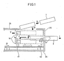
- the cassette when a large size cassette 3 is introduced in a direction shown by the arrow mark I from a front cabinet 35, the cassette is loaded to the loading position for recording and/or reproduction, as it is held by a slider in the direction shown by the arrow mark II.
- the cassette is introduced from an upper cabinet 24 in the direction shown by the arrow mark III, and lowered in the direction shown by the arrow mark IV, so as to be attached in position in within an adapter chassis 14.
- the adapter chassis 14 is lowered in the direction shown by the arrow mark VI for loading the small size cassette 1 in the predetermined recording/reproducing position.
- the adapter chassis 14 having the small size cassette 1 attached thereto When the adapter chassis 14 having the small size cassette 1 attached thereto is lowered, the adapter chassis 14 may be contacted with the large size cassette or the hand occasionally introduced into the cabinet, thus causing a damage to the device.
- a slider for holding and securing the large size cassette 3 is positioned in the downward path, of travel of the adapter chassis 14. Therefore, when loading the small size cassette 1, it is necessary to shift the slider along the direction shown by the arrow mark II while the large size cassette 3 is not introduced into the cabinet. In the course of the movement of the slider, when the large size cassette 3, foreign matter or hand is introduced from the front cabinet 35, there is the risk that various component parts of the mechanism of the magnetic recording/reproducing device may be damaged.
- the problem of the impaired operational safety is also presented in a cassette control unit dedicated to large or small size cassettes. That is, the component parts of the mechanism of the magnetic recording reproducing device may be impaired by the foreign matter, hand or finger inserted via the cassette inserting opening after the large size cassette or the small size cassette is introduced via the predetermined cassette inserting opening so as to be loaded to the predetermined magnetic recording/reproducing position. For example, when the small size cassette is inserted by mistake via the large cassette inserting opening, there is the risk that other mechanisms or cassettes in the magnetic recording and/or reproducing device may be damaged.
- the cassette loading mechanism includes a casing, a lid, a first engaging portion, a second engaging portion, a first urging portion and a second urging portion.
- the casing is provided with an inserting opening profiled to receive the cassette to be introduced therein.
- the lid is movably attached to the casing for opening or closing the inserting opening.
- the first engaging portion can be engaged with the lid and is mounted to one of mutually confronting edge portions of the lid for movement between a position engaging the with the lid and a position not engaging with the lid.
- the second engaging portion can be engaged with the lid and is provided to the other of the mutually confronting edge portions for movement between the position engaging with the lid and the position not engaging with the lid. This second engaging portion is operated independently of the first engaging portion.
- the first urging portion urges the first engaging portion for holding the first engaging portion at the position engaging with the lid.
- the second urging portion urges the second engaging portion for holding the second engaging portion at the position engaging with the lid.
- the first engaging portion includes an abutting portion abutting on the cassette introduced via the inserting opening and shifting the first engaging portion to its non-engaging position responsive to the cassette inserting operation.
- the second engaging portion has an abutting portion abutting on the cassette introduced via the inserting opening and shifting the second engaging portion to its non-engaging position responsive to the cassette inserting operation.
- the lid is rotatably attached to the casing.
- An arm is preferably mounted to the casing so that the arm may be rotated in operative association with the rotation of the lid.
- the lid has a an abutment portion abutting on the cassette introduced via the inserting opening and turning the lid to the position of opening the inserting opening responsive to the cassette inserting operation.
- the arm may be provided with an abutment portion for abutting on the cassette introduced or taken out via the inserting opening and turning the arm responsive to the cassette inserting or taking-out operation.
- the cassette loading mechanism is so designed that the first and second engaging portions are moved to the position of not engaging with the lid only when a predetermined type cassette is introduced via the cassette inserting opening.
- the first and second engaging portions are provided at the mutually confronting edge portions of the lid and are operative separately. Therefore, the lid cannot be opened even when a cassette other than the predetermined type cassette is introduced via the inserting opening so that one of the first and second engaging portions is shifted to the position of not engaging with the lid. Therefore, the lid is opened only when the predetermined type cassette is introduced via the inserting opening but is not opened otherwise. As a result, it is possible to prevent the occurrence of the situation in which the foreign matter, hand or finger be inserted into the cassette inserting opening or a cassette of a different size be introduced by mistake into the cassette inserting opening. This results in an improved cassette loading operation.
- the cassette loading mechanism is so designed that plural kinds of cassettes of different sizes can be loaded selectively into the recording/reproducing position.
- This cassette loading mechanism includes a casing, a holding section for a large size cassette, a shifting section for a large size cassette, a holding section for a small size cassette, a shifting section for a small size cassette, a lid, a first engaging portion, a second engaging portion, a first urging portion and a second urging portion.
- the casing is provided with an inserting opening for a large size cassette profiled to receive the large size cassette, and an inserting opening for a small size cassette profiled to receive the small size cassette.
- the holding section for the large size cassette holds the large size cassette introduced into the casing via the inserting opening for the large size cassette at the predetermined position.
- the shifting section for the large size cassette shifts the holding section for the large size cassette between the inserting position for the large size cassette and the position of recording and/or reproduction.
- the holding section for the small size cassette holds the small size cassette introduced into the casing via the inserting opening for the small size cassette at the predetermined position.
- the shifting section for the small size cassette shifts the holding section for the small size cassette between the inserting position for the small size cassette and the position for recording and/or reproduction.
- the holding section for the small size cassette can be attached to the holding section for the large size cassette that has been shifted to the recording/reproducing position.
- the lid is movably attached to the casing for opening the inserting opening for the large size cassette.
- the first engaging portion can be engaged with the lid and is provided to one of mutually confronting edge portions of the lid for movement between the position of engaging with the lid and the position of not engaging with the lid.
- the second engaging portion can be engaged with lid and is provided to the other of the mutually confronting edge portions of the lid for movement between the position of engaging with the lid and the position of not engaging with the lid.
- the second engaging portion operates separately from the first engaging portion.
- the first urging portion urges the first engaging portion for holding the first engaging portion at the position of engaging with the lid.
- the second urging portion urges the second engaging portion for holding the second engaging portion at the position of engaging with the lid.
- the first engaging portion has the first abutment portion abutting on the cassette introduced via the large size cassette inserting opening and adapted for shifting the first engaging portion to its non-engaging portion responsive to the inserting operation of the cassette.
- the second engaging portion has a second abutment portion abutting on the cassette introduced via the large cassette inserting opening and adapted for shifting the second engaging portion to its non-engaging position responsive to the inserting operation of the cassette. Both the first and second abutment portions can abut on the large size cassette introduced via the large cassette inserting opening. One of the first and second abutment portions can abut on the small size cassette introduced via the large size cassette inserting opening.
- means for sensing the opening and/or closure of the lid is provided at the large size cassette inserting opening for sensing the opened and/or closed state of the lid.
- the cassette loading mechanism is so designed that the first and second abutment portions abut on the large size cassette only when the large size cassette is introduced via the large cassette inserting opening.
- the first and the second abutment portions can abut on the inserted object.
- the first and the second engaging portions provided respectively with the first and the second abutment portions are actuated separately, so that the lid can be opened only when the large size cassette is introduced via the large size cassette inserting opening.
- the lid cannot be opened even when one of the engaging portions has been able to shift the lid to its non-engaging position. Therefore, the lid provided to the large size cassette inserting opening can be opened only when the large size cassette is introduced, but cannot be opened when any other object is introduced. When an object other than the large size cassette is introduced, the lid is kept in the closed state. As a result, the operational safety of the cassette loading operation may be improved in the cassette loading mechanism in which the large size cassette and the small size cassette can be loaded electively.
- Figs. 2 to 10 illustrate an embodiment of a magnetic recording/reproducing device according to the present invention.
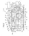
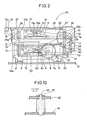
- Figs. 2 and 3 are left-hand side views of a cassette control unit K1. It is noted that the right-hand side view of the cassette control unit K1 is the same as the left-hand side view as long as the mechanism thereof is concerned.
- Figs. 6 and 7 are a left-hand side view and a plan showing an adapter chassis used for inserting the small size cassette, respectively.
- a guide plate 7 is provided with L-shaped grooves 7a and 7b and two straight grooves 7c and 7d.
- the guide plate 7 is secured to a main chassis 12 by two set screws 13.
- a driving gear 8 is rotatably mounted to the guide plate 7.
- a driving arm 9 is secured to the driving gear 8.
- a loading gear 10 is rotatably mounted to the guide plate 7.
- a loading arm 11 is secured to the loading gear 10.
- a slider 6 is provided with a first guide shaft 6a and a second guide shaft 6b. The first guide shaft 6a and the second guide shaft 6b are introduced into the L-shaped grooves 7a and 7b of the guide plate 7.
- the second guide shaft 6b is inserted into a U shaped groove 9a of the driving arm 9.
- each four loading guide shafts 25 are provided to both sides of the loading chassis 25. Two each of these loading guide shafts 25a are introduced into the straight grooves 7c and 7d of the guide plate 7.
- a loading shaft 25b is provided to the loading chassis 25. This loading shaft 25b is introduced into an oblong hole 11a of the loading arm 11.
- a lid 15 for a small size cassette is attached to the guide plate 7 for rotation about a supporting shaft 15a. This lid for the small size cassette 15 is urged by a return spring 16 in the closing direction.
- a first housing arm 17 is mounted to the adapter chassis for rotation about a shaft 17a as fulcrum.
- a second housing arm 18 has its one end slidably attached in an oblong opening 14a of the adapter chassis 14.
- the first housing arm 17 and the second housing arm 18 are rotatably engaged with each other in the vicinity of the mid portions thereof as shown.
- the first housing arm 17 and the second housing arm 18 are mounted for rotation to a housing 19.
- a lifting spring 20 is engaged with the first housing arm 17 and the second housing arm 18 for uplifting the housing 19.
- the adapted chassis 14 is provided with positioning holes 14b and 14c at the positions corresponding to those of the large size cassette 3.
- a phase gear is provided to each of the left-side and right-side driving gears 8 for causing these driving gears to rotate in phase with each other.
- the left-side and right-side loading gears 10 are also each provided with a phase gear for causing these gears to rotate in phase with each other.
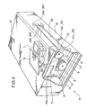
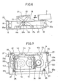
- Fig. 4 is a perspective view diagrammatically showing a magnetic recording/reproducing device according to the present invention.
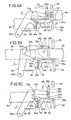
- Figs. 5A to 5C are diagrammatic view for illustrating the operation of the lid for large size cassette 28 provided to a large size cassette inserting opening of the cassette control unit K1.
- a lid for a large size cassette 28 is provided to a large size cassette inserting opening in a front cabinet 35.
- Locking levers 34L, 34R are provided on both end edges of the lid 28 for locking the lid 28.
- Lock lever springs 37L, 37R for urging the levers 34L, 34R for holding these locking levers in the position of locking the lid 28 are provided to the lock levers 34L and 34R, respectively.
- Opening levers 33L, 33R are provided for rotation in operative association with the opening and closure of the lid 28.
- These opening levers 33L, 34R are provided with opening lever spring 36L, 36R for urging the opening levers for holding the opening levers at the position in which the lid 28 closes the large size cassette inserting opening.
- opening levers 33L, 33R, locking levers 34L, 34R opening levers spring 36L, 36R and the locking lever springs 37L, 37R are shown diagrammatically for illustrating only the relative position thereof with respect to the lid 28 in the control unit K1.
- FIGs. 2, 3, and 5A to 5C the opening and closing mechanism and the locking mechanism for the lid 28 for the large size cassette will be explained.
- FIGs. 5A to 5C the opening and closing mechanism and the locking mechanism for the lid 28 will be explained with respect only to the left-side mechanism of the lid for the large size cassette 28.
- left-side and right-side opening levelers 33L, 33R are shown in Fig. 4, whereas only one opening lever is shown in Figs. 5A to 5C and indicated by the reference numeral 33.
- the opening lever 33 is rotatably mounted to the guide plate 7, and the lid 28 is mounted to the guide plate 7 for rotation about the supporting shaft 28b.
- the supporting shaft 28b is inserted into an opening 7e of the guide plate 7.
- the lid 28 is urged by a lid spring 29 into abutment with a stopper 7f of the guide plate 7.
- the opening lever 33 is engaged at 33c in a groove 28a of the lid 28.
- the opening lever 33 is provided with a pin 33a for extending inwardly from the mutually confronting opening levers 33L , 33R so as not to interfere with other operating portions. This pin 33a is able to contact with one of left-side and right-side upper surface portions of the large size cassette 3 introduced into the device.
- the opening lever 33 is urged by an opening lever spring 36 in the clockwise direction.
- a locking lever 34 is mounted on to a guide member 38 adapted for guiding the large size cassette 3 being introduced in the device for rotation about a supporting shaft 34e.
- the locking lever 34 is urged by a locking lever spring 37 into abutment with the upper portion 38a of the guide member 38.
- the lid 28 is urged into abutment on the stopper 7f of the guide plate 7 since the opening lever 33 is urged in the clockwise direction by the opening lever spring 36.
- the locking levers 34L, 34R are provided, one each at the both side edges of the lid 28, for abutting on the end edges of the large size cassette 3 as it is introduced into the device.
- locking of the lid 28 can not be released unless the left-side and right-side locking levers 34L, 34R are pressed down simultaneously. Therefore, locking of the lid 28 can not be released by intrusion of the hand or finger.
- the lid 28 is opened, the pin 33a of the opening lever 33 abutting on the upper surface of the large size cassette 3. This causes the opening lever 33 to be turned in the direction shown by the arrow mark C.
- a loading motor not shown is driven as described later so that the large size cassette is moved from the position 3b to the position 3c (Fig. 5B) through a position 3d (Fig. 5C) and thence to the position 3e shown in Fig. 5A. This terminates the loading of the large size cassette.
- the opening levers 33 are returned to the original position and the lid 28 continues to be locked by the locking lever 34.
- the loading motor is reversed in its operation, so that the large size cassette 3 is moved from the position shown at 3e to the position shown at 3d.
- the large size cassette 3 thrusts the pin 33a of the opening lever 33, so that the opening lever 33 is turned in the direction shown by the arrow mark C.
- the opening lever thrusts at 33b the locking lever 34 at 34d, so that the locking lever 34 is turned in the direction shown by the arrow mark E.
- the lid 28 may not be opened.
- the opening lever 33 is turned further in the direction shown by the arrow mark C.
- the lid 28 may be opened with the turning movement of the opening lever 33.
- the large size cassette 3 is moved from the position shown at the 3b to the position shown at 3a so as to be taken out from the device. It is noted that the opening lever 33 and the locking lever 34 are contacted flat with the large size cassette 3 only at portions 34a, 33a 34b, 34c while the remaining portion of the opening lever 33 and the locking lever 34 are adapted to clear the large size cassette.
- the large size cassette inserting opening is provided with a lid switch 30.
- This lid switch is attached to the guide plate 7 by a set screw 31.
- the lid switch 30 is included in an electrical circuit which is closed when the lid 28 is closed and which is opened when the lid is opened even slightly.
- a loading start switch not shown, senses that the large size cassette has been introduced to a predetermined position, the driving motor, not shown, is driven for turning the driving gear 8 and the driving arm 9 in the direction shown by the arrow mark A.
- the second guide shaft 6b is driven by this turning movement of the gear 8 and the arm 9.
- the slider 6 is moved horizontally as it is guided along the two L-shaped grooves 7a and 7b in the guide plate 7.
- the slider 6 then is moved vertically downward to a position shown at 6P in Fig. 2.
- the large size cassette 3 is positioned to complete the loading of the large size cassette. The positioning of this large cassette 3 will be explained later.
- the driving motor is reversed in operation and the operation which is the reverse of the above described operation is preformed to take out the large size cassette 3.
- the cassette 1 is inserted into the housing 19 by the manual operation in the direction shown by the arrow mark III.
- This causes the small size cassette 1 to be pressured and secured to the housing 19 with the aid of a spring 21 for small size cassette which is secured to the housing 19.
- the housing 19 is at the position shown in Fig. 2.
- the housing 19 is then pressed down to shift the housing 19 to the position shown in Fig. 3.
- the housing 19 is now attached and locked to the adapter chassis 12 by a locking mechanism, not shown, attached to the adapter chassis 14.
- the adapter 14 is at the position shown at 14S in Fig. 2.
- a locking sensor switch and a small size cassette sensor switch sense that the small size cassette 1 is introduced and the housing 19 is locked in position.
- a housing motor not shown, operates to drive a first tape extraction arm 22 and a second tape extraction and 23.
- An end roll is mounted for rolling at each of the first tape extraction room 22 and the second tape extraction arm 23.
- the first tape extraction arm 22 and the second tape extraction arm 23 are attached for rotation to the adapter chassis 14.
- the magnetic tape 1a is extracted to a predetermined position 1d, as shown in Fig. 7, under the driving by this first plate extraction room 22 and the second tape extraction arm 23.
- the state of the lid switch 30 is sensed.
- the electrical circuit of the lid switch is closed, it is determined with respect to the state of the large cassette inserting opening that the large size cassette or the hand has not been introduced into this inserting opening.
- the driving motor is driven into operation.
- the slider 6 is shifted to the position shown at 6P in Fig. E, that is, to the position for recording and/or reproduction, in the same way as when the large size cassette 3 is loaded.
- the electrical circuit of the lid switch 30 is closed, it is determined with respect to the state of the large cassette inserting opening that the large size cassette or the hand has been inserted into this inserting opening. At this time, this state is indicated in a VTR display section, not shown.
- This indication on the VTR display section indicates the user of the cassette control unit to take out the large size cassette 3 or the hand from the inserting opening.
- the state of the lid switch 30 is sensed repeatedly.
- the slider 6 is shifted, in the same way as described hereinabove. The operation of the slider 6 is terminated on closure of the circuit of the lid switch 30.
- the loading motor not shown, is driven into operation.
- the loading gear 10 and the loading arm 11 are turned in the direction shown by the arrow mark B.
- the loading chassis 25 is lowered as it is maintained in the horizontal state and guided into straight grooves 7c and 7d in the guide plate 7.
- the adapter chassis 14 is attached to the loading chassis 25, so that it is lowered together with the loading chassis 25. At this time, the adapter chassis 14 is guided and moved in register with two positioning pin 41.
- the position and the height level of the adapter chassis 14 is determined by that the adapter chassis 14 is loaded on the foremost parts of the two positioning pin 42 and the flattened end portions of the two positioning pins 41.
- the position and the height level of the adapter chassis is those shown at 14Q in Fig. 3.
- the adapter chassis 14 is positioned by the two positioning pins 41 and two positioning pins 42, as when the large size cassette 3 is loaded, so as to be pressured and secured by the pressuring spring, not shown, provided to the loading chassis 25.
- the slider 6 is not provided with a ceiling plate, as shown in Fig. 8.
- the adapter chassis 14 is provided with a clearance 14d to avoid collision with the spring for the large size cassette 4, as shown in Fig. 7.
- the small size cassette 1 is attached.
- the state of the lid switch 30 is sensed and, when it is in the closed state, the operation is continued.
- the lid switch 30 is in the open state, the operation of the loading motor is discontinued to terminate the lowering of the adapter chassis 14.
- the state of the lid switch 30 is sensed at the time of loading the small size cassette 1 to provide for improved safety in the cassette loading operation.
- the lid 28 is locked against opening by the locking lever 34 unless the large size cassette 3 is introduced.
- the adapter chassis 14 is provided with a portion abutting on the locking lever 34 at 34a, similarly to the large size cassette 3 located at the position 3e shown in Fig. 5A. For this reason, the lid 28 continues to be locked even when the adapter chassis 14 is positioned at the recording/reproducing position. This locking of the lid 28 provides for duplex prevention of the occurrence of mistaken operation at the large size cassette inserting opening, so that the operational safety in the loading of small size cassettes is improved.
- the small size cassette 1 is provided with a supply reel 1b and a take-up reel 1c.
- the magnetic tape 1 is placed about the supply reel 1b and the take-up reel 1c.
- a gear is cut on the half portion of the take up reel 1c.
- the take-up reel 1c meshes with the drive gear 2c mounted for rotation to the adapter chassis 14.
- the driving gear 2c meshes with the driving reel 2d.
- the driving reel 2d and the supply reel 1b are driven into operation by a reel motor, not shown.
- the loading chassis 25 and the adapter chassis 14 are raised by the loading motor by the operation which is the reverse of that for loading.
- the state of the lid switch 30 is sensed, in the same way as when the adapter chassis 14 is lowered.
- the operation of the loading motor is terminated.
- the operation of the driving motor is reversed.
- the slider is moved to its original position by the operation similar to that for ejecting the large size cassette 3.
- the first tape extraction arm 22 and the second tape extraction are 23 are driven in the direction which is reverse of that described hereinabove. That magnetic tape 1a is returned to its original position.
- the locking of the housing 19 is released.
- the housing 19 is raised by the operation of an uplifting spring 20.
- the lid for the small size cassette 15 is opened to allow for taking out of the small size cassette 1.
- the switch for detecting the insertion of the small size cassette 1 is not activated, even when the housing 19 is pressed down for attachment and locking to the adapter chassis 14.
- the first and second tape extraction arms 22, 23 are not driven into operation and, hence, the adapter chassis 14 is not lowered. Consequently, when the small size cassette 1 is not in use, the lid for the small size cassette 19 may be closed by lowering the housing 19 for attaching and locking the housing 19 to the adapter chassis 14.
- the adapter chassis 14 is not lowered at this time, so that it does not interfere with the insertion of the large size cassette 3.
- the small size cassette 1, hand, finger or other foreign matter may not be introduced via the large size cassette opening during loading or ejection of the small size cassette 1.
- the large size cassette can be introduced via the large size cassette inserting opening.
- the lid 28 cannot be opened unless the large size cassette is introduced erroneously. It is therefore possible to provide a detection device whereby the state of opening of the lid 28 is determined to be an unusual occurrence based on which to terminate the operation. This prevents destruction of the cassette or other mechanisms of the magnetic recording and/or reproducing device.
- a lever or the like for preventing insertion of the large size cassette in association with the operation of the slider 6 may be provided for preventing the large size cassette 3 from being introduced in the loaded state of the small size cassette 1.
- the two positioning pins 41 and two positioning pins 42 are provided to the main chassis 12 for positioning the adapter chassis during loading of the small size cassette 1.
- the position of the adapter chassis 14 is influenced by the positioning precision of the loading chassis 25.
- the loading position of the small size cassette 1 is determined by the position of the adapter chassis 14 which is determined by the medium of the loading chassis 25.
- the aforementioned two positioning pins 41 and two positioning pins 42 used for positioning the adapter chassis 14 are intrinsically employed for precision positioning of the large size cassette.
- the positioning of the large size cassette is hereinafter explained in detail.
- Figs. 8 and 9 are a perspective view and a side-elevational view showing only the large size cassette inserting portion in the cassette control unit of the magnetic recording and/or reproducing device.
- the large size cassette 3 when the large size cassette 3 is inserted in the direction shown by the arrow mark I, the both sides and the lower surface of the large size cassette are surrounded by the slider 6.
- the forward surface of the large size cassette 3 is regulated by the stopper 6c.
- the large size cassette 3 is pressured and secured to the lower portion of the slider 6 by two springs for large size cassette 4.
- the slider has a width slightly larger than the size of the large size cassette 3. Therefore, when the large size cassette 3 is secured to the slider only by the pressuring of the spring for the large size cassette 4, the large size cassette 3 is movable to some extent in the interior of the slider 6.
- the drive gear 8 is driven into rotation to turn the driving arm 9.
- the second guide shaft 6b of the slider 6 is guided and moved within the groove 7a of the guide plate 7, as the guide shaft 6b is intruded into the groove 9a of the driving arm 9.
- the first guide shaft 6a of the slider 6 is also guided within the groove 7b of the guide plate 7. This causes the slider 6 to be loaded in the direction by the arrow mark II.
- the large size cassette 3, pressured and secured to the slider by the spring for the large size cassette 4 may also be loaded in the similar manner. At this time, the loading position of the large size cassette 3 is determined by the two positioning pins 41.
- the loading position of the large size cassette 3 is determined by that the two positioning pins 41 are introduced into openings provided in the lower surface of the large size cassette 3.
- the loading height position of the large size cassette is determined by the flat portions of the two positioning pins 42 and the two positioning pins 41, as shown at VII in Fig. 7.
- the adapter chassis 14 is provided with openings 14b, 14c at the positions corresponding to those of the large size cassette 3, for receiving the positioning pin 41.
- the positioning of the adapter chassis 14 is achieved by the positioning pins 41.
- the adapter chassis is secured to the loading chassis 25.
- the loading chassis is moved along the guide groove provided in the guide plate 7. Therefore, the positioning precision of the adapter chassis 14 is influenced by that of the loading chassis 25.
- FIG. 10 is a sectional view showing the portion of the adapter chassis 14 secured to the loading chassis 25.
- the end section of the adapter shaft 26 is tapered.
- the tapered portion of the adapter shaft 26 is formed with a groove for receiving an E-ring.
- the adapter shaft 26 is inserted into the opening provided in the loading chassis 25.
- the adapter shaft 26 and the loading chassis 25 are secured by this E-ring 27.
- the distance between the portion of the adapter shaft 26 receiving the E-ring and the portion thereof having a larger diameter is selected to be slightly larger than the plate thickness of the loading chassis 15.
- the diameter of the opening in the loading chassis 25 is also selected to be larger than the small diameter of the adapter shaft 26.
- the adapter chassis 14 is mounted so as to movable with respect to the loading chassis 25 by an amount corresponding to the difference in the opening diameters. Consequently, even when the loading chassis 25 is moved with a more or less deviation during movement of the adapter chassis 14 to the recording and/or reproducing position by the medium of the loading chassis 25, the adapter chassis 14 is moved slightly with respect to the loading chassis 25, the two position pin 41 intruding into the positioning openings 14b, 14c. In this manner, precise positioning of the adapter chassis 14 may be achieved during loading of the small size cassette.
- the present invention provides a cassette loading mechanism provided with a mechanism whereby locking of the lid is released only when a predetermined cassette is introduced therein to allow for opening of the lid, so that the operational safety of the cassette loading operation is improved.
Landscapes
- Automatic Tape Cassette Changers (AREA)
- Feeding And Guiding Record Carriers (AREA)
- Toys (AREA)
- Packaging Of Annular Or Rod-Shaped Articles, Wearing Apparel, Cassettes, Or The Like (AREA)
Applications Claiming Priority (4)
| Application Number | Priority Date | Filing Date | Title |
|---|---|---|---|
| JP63157824A JPH07114051B2 (ja) | 1988-06-24 | 1988-06-24 | 磁気記録再生装置のカセット装填機構 |
| JP157823/88 | 1988-06-24 | ||
| JP157824/88 | 1988-06-24 | ||
| JP63157823A JPH06101173B2 (ja) | 1988-06-24 | 1988-06-24 | 磁気記録再生装置のカセット装填機構 |
Publications (3)
| Publication Number | Publication Date |
|---|---|
| EP0348242A2 true EP0348242A2 (de) | 1989-12-27 |
| EP0348242A3 EP0348242A3 (de) | 1991-03-13 |
| EP0348242B1 EP0348242B1 (de) | 1996-03-20 |
Family
ID=26485138
Family Applications (1)
| Application Number | Title | Priority Date | Filing Date |
|---|---|---|---|
| EP89306430A Expired - Lifetime EP0348242B1 (de) | 1988-06-24 | 1989-06-26 | Kassetten-Lademechanismus |
Country Status (9)
| Country | Link |
|---|---|
| US (1) | US4992894A (de) |
| EP (1) | EP0348242B1 (de) |
| KR (1) | KR930000685B1 (de) |
| CN (1) | CN1014564B (de) |
| AU (1) | AU611564B2 (de) |
| BR (1) | BR8903081A (de) |
| CA (1) | CA1332464C (de) |
| DE (1) | DE68925997T2 (de) |
| ES (1) | ES2083970T3 (de) |
Cited By (3)
| Publication number | Priority date | Publication date | Assignee | Title |
|---|---|---|---|---|
| EP0541355A3 (en) * | 1991-11-06 | 1994-05-25 | Sony Corp | Recording and/or reproducing apparatus |
| EP0503359A3 (en) * | 1991-03-08 | 1994-09-28 | Toshiba Kk | Cassette data detecting apparatus of system for mounting a plurality of cassettes |
| EP0570134A3 (de) * | 1992-05-06 | 1994-12-21 | Matsushita Electric Industrial Co Ltd | Kassettenladegerät. |
Families Citing this family (5)
| Publication number | Priority date | Publication date | Assignee | Title |
|---|---|---|---|---|
| JPH02306460A (ja) * | 1989-05-19 | 1990-12-19 | Toshiba Corp | カセット装填装置 |
| US5357385A (en) * | 1989-08-17 | 1994-10-18 | Victor Company Of Japan, Ltd. | Tray-type cassette loading compatible with two different sized cassettes for recording/reproducing apparatus |
| DE69025717T2 (de) * | 1989-12-07 | 1996-10-17 | Victor Company Of Japan | Kassettenladevorrichtung für Video-Kassettenaufzeichnungsgerät |
| JP4844018B2 (ja) * | 2005-06-15 | 2011-12-21 | ミツミ電機株式会社 | カートリッジホルダ装置 |
| DE102016121646B3 (de) * | 2016-11-11 | 2018-04-26 | Jos. Schneider Optische Werke Gmbh | Adapter zum Verschwenken eines Objektivs |
Family Cites Families (15)
| Publication number | Priority date | Publication date | Assignee | Title |
|---|---|---|---|---|
| CA930469A (en) * | 1968-12-09 | 1973-07-17 | Matsushita Electric Industrial Co., Ltd. | Magnetic recording and reproducing apparatus |
| JPS5463731A (en) * | 1977-10-13 | 1979-05-22 | Olympus Optical Co Ltd | Cassette type magnetic recorder-reproducer |
| JPS6044740B2 (ja) * | 1980-11-25 | 1985-10-05 | 日本ビクター株式会社 | テ−プカセツト |
| JPS58128048A (ja) * | 1982-01-25 | 1983-07-30 | Canon Inc | 情報の記録又は再生装置 |
| JPS59227062A (ja) * | 1983-06-07 | 1984-12-20 | Victor Co Of Japan Ltd | 磁気記録及び/又は再生装置 |
| JPS59193502A (ja) * | 1983-04-19 | 1984-11-02 | Victor Co Of Japan Ltd | 磁気記録及び/又は再生装置 |
| BR8401829A (pt) * | 1983-04-19 | 1984-11-27 | Victor Company Of Japan | Aparelho de gravacao e/ou reproducao magnetico |
| JPS59227061A (ja) * | 1983-06-07 | 1984-12-20 | Victor Co Of Japan Ltd | 磁気記録及び/又は再生装置 |
| JPS601643A (ja) * | 1983-06-17 | 1985-01-07 | Victor Co Of Japan Ltd | 磁気記録及び/又は再生装置 |
| JPS609037A (ja) * | 1983-06-28 | 1985-01-18 | Toshiba Corp | 補強型陰極線管 |
| JPS6064441U (ja) * | 1983-10-05 | 1985-05-07 | 日本ビクター株式会社 | テ−プ収納筐体挿入口蓋ロツク機構 |
| DE3626941A1 (de) * | 1986-08-08 | 1988-02-11 | Bosch Gmbh Robert | Zentriervorrichtung fuer magnetbandkassetten unterschiedlicher abmessungen in einem kassettenschacht |
| JPS6442051A (en) * | 1987-08-07 | 1989-02-14 | Sharp Kk | Magnetic recording and reproducing device |
| US4786996A (en) * | 1987-04-16 | 1988-11-22 | Sony Corporation | Cassette tape with guiderails on cassette holder apparatus |
| US4897744A (en) * | 1987-05-29 | 1990-01-30 | Matsushita Electric Industrial Co., Ltd. | Apparatus for selectively loading small or large tape cassettes |
-
1989
- 1989-05-30 CA CA000601102A patent/CA1332464C/en not_active Expired - Lifetime
- 1989-05-31 AU AU35869/89A patent/AU611564B2/en not_active Expired
- 1989-06-22 US US07/370,335 patent/US4992894A/en not_active Expired - Lifetime
- 1989-06-23 BR BR898903081A patent/BR8903081A/pt not_active IP Right Cessation
- 1989-06-24 KR KR1019890008757A patent/KR930000685B1/ko not_active Expired - Lifetime
- 1989-06-24 CN CN89104385A patent/CN1014564B/zh not_active Expired
- 1989-06-26 ES ES89306430T patent/ES2083970T3/es not_active Expired - Lifetime
- 1989-06-26 DE DE68925997T patent/DE68925997T2/de not_active Expired - Lifetime
- 1989-06-26 EP EP89306430A patent/EP0348242B1/de not_active Expired - Lifetime
Cited By (4)
| Publication number | Priority date | Publication date | Assignee | Title |
|---|---|---|---|---|
| EP0503359A3 (en) * | 1991-03-08 | 1994-09-28 | Toshiba Kk | Cassette data detecting apparatus of system for mounting a plurality of cassettes |
| EP0541355A3 (en) * | 1991-11-06 | 1994-05-25 | Sony Corp | Recording and/or reproducing apparatus |
| US5625507A (en) * | 1991-11-06 | 1997-04-29 | Sony Corporation | Recording and/or reproducing apparatus that loads a tape cassette into standby position while recording and/or reproducing with another tape cassette |
| EP0570134A3 (de) * | 1992-05-06 | 1994-12-21 | Matsushita Electric Industrial Co Ltd | Kassettenladegerät. |
Also Published As
| Publication number | Publication date |
|---|---|
| KR930000685B1 (ko) | 1993-01-29 |
| US4992894A (en) | 1991-02-12 |
| CA1332464C (en) | 1994-10-11 |
| KR900000876A (ko) | 1990-01-31 |
| BR8903081A (pt) | 1990-02-06 |
| ES2083970T3 (es) | 1996-05-01 |
| CN1039673A (zh) | 1990-02-14 |
| CN1014564B (zh) | 1991-10-30 |
| DE68925997T2 (de) | 1996-10-02 |
| AU611564B2 (en) | 1991-06-13 |
| AU3586989A (en) | 1990-01-04 |
| DE68925997D1 (de) | 1996-04-25 |
| EP0348242B1 (de) | 1996-03-20 |
| EP0348242A3 (de) | 1991-03-13 |
Similar Documents
| Publication | Publication Date | Title |
|---|---|---|
| US5032939A (en) | Tape cassette loading system compatible with two different sized cassettes | |
| JPH0636522Y2 (ja) | ディスクカートリッジの誤挿入防止機構 | |
| EP0307917B1 (de) | Fronttürmechanismus für Gerät zur Signalaufzeichnung und Wiedergabe unter Verwendung einer Kassette | |
| JPH0348765Y2 (de) | ||
| EP0393647B1 (de) | Tragbares Aufzeichnungs- und/oder Wiedergabegerät | |
| US4992894A (en) | Cassette loading mechanism | |
| US5008766A (en) | Tape cassette attachment device with closure plate actuated insertion sensor | |
| EP0342619B1 (de) | Magnetisches Aufzeichnungs- und Wiedergabegerät | |
| US6233110B1 (en) | Disc driving device with rotational velocity control | |
| US4628376A (en) | Magnetic disc unit | |
| US4686593A (en) | Overriding loading door for a magnetic recording/reproducing apparatus | |
| JPH0237623B2 (de) | ||
| KR950003984B1 (ko) | 복수 카세트 탑재 기기의 카세트 정보 검출 장치 | |
| JPH027261A (ja) | 磁気記録再生装置のカセット装填機構 | |
| JP2956986B2 (ja) | カセット装着装置 | |
| JPH07502362A (ja) | カセット装填装置 | |
| JP2567980B2 (ja) | 自動装填装置の危険防止機構 | |
| JPH0760546B2 (ja) | カセット装着装置 | |
| JP2626123B2 (ja) | カセット装着装置 | |
| JPH0652598B2 (ja) | テープカセット装着装置 | |
| JPH02183457A (ja) | テープカセット装着装置 | |
| JP2978578B2 (ja) | カートリッジ自動装着装置 | |
| JPS60103551A (ja) | 記録再生装置 | |
| JPH06101173B2 (ja) | 磁気記録再生装置のカセット装填機構 | |
| JPH0450670B2 (de) |
Legal Events
| Date | Code | Title | Description |
|---|---|---|---|
| PUAI | Public reference made under article 153(3) epc to a published international application that has entered the european phase |
Free format text: ORIGINAL CODE: 0009012 |
|
| AK | Designated contracting states |
Kind code of ref document: A2 Designated state(s): DE ES FR GB |
|
| PUAL | Search report despatched |
Free format text: ORIGINAL CODE: 0009013 |
|
| 17P | Request for examination filed |
Effective date: 19901214 |
|
| AK | Designated contracting states |
Kind code of ref document: A3 Designated state(s): DE ES FR GB |
|
| 17Q | First examination report despatched |
Effective date: 19930526 |
|
| GRAH | Despatch of communication of intention to grant a patent |
Free format text: ORIGINAL CODE: EPIDOS IGRA |
|
| GRAH | Despatch of communication of intention to grant a patent |
Free format text: ORIGINAL CODE: EPIDOS IGRA |
|
| GRAA | (expected) grant |
Free format text: ORIGINAL CODE: 0009210 |
|
| AK | Designated contracting states |
Kind code of ref document: B1 Designated state(s): DE ES FR GB |
|
| REF | Corresponds to: |
Ref document number: 68925997 Country of ref document: DE Date of ref document: 19960425 |
|
| REG | Reference to a national code |
Ref country code: ES Ref legal event code: FG2A Ref document number: 2083970 Country of ref document: ES Kind code of ref document: T3 |
|
| ET | Fr: translation filed | ||
| PLBE | No opposition filed within time limit |
Free format text: ORIGINAL CODE: 0009261 |
|
| STAA | Information on the status of an ep patent application or granted ep patent |
Free format text: STATUS: NO OPPOSITION FILED WITHIN TIME LIMIT |
|
| 26N | No opposition filed | ||
| REG | Reference to a national code |
Ref country code: GB Ref legal event code: IF02 |
|
| PGFP | Annual fee paid to national office [announced via postgrant information from national office to epo] |
Ref country code: ES Payment date: 20080708 Year of fee payment: 20 Ref country code: DE Payment date: 20080703 Year of fee payment: 20 |
|
| PGFP | Annual fee paid to national office [announced via postgrant information from national office to epo] |
Ref country code: FR Payment date: 20080617 Year of fee payment: 20 |
|
| PGFP | Annual fee paid to national office [announced via postgrant information from national office to epo] |
Ref country code: GB Payment date: 20080702 Year of fee payment: 20 |
|
| REG | Reference to a national code |
Ref country code: GB Ref legal event code: PE20 Expiry date: 20090625 |
|
| REG | Reference to a national code |
Ref country code: ES Ref legal event code: FD2A Effective date: 20090627 |
|
| PG25 | Lapsed in a contracting state [announced via postgrant information from national office to epo] |
Ref country code: ES Free format text: LAPSE BECAUSE OF EXPIRATION OF PROTECTION Effective date: 20090627 |
|
| PG25 | Lapsed in a contracting state [announced via postgrant information from national office to epo] |
Ref country code: GB Free format text: LAPSE BECAUSE OF EXPIRATION OF PROTECTION Effective date: 20090625 |