EP0350013B1 - Méthode de réglage pour le soudage par résistance - Google Patents
Méthode de réglage pour le soudage par résistance Download PDFInfo
- Publication number
- EP0350013B1 EP0350013B1 EP89112290A EP89112290A EP0350013B1 EP 0350013 B1 EP0350013 B1 EP 0350013B1 EP 89112290 A EP89112290 A EP 89112290A EP 89112290 A EP89112290 A EP 89112290A EP 0350013 B1 EP0350013 B1 EP 0350013B1
- Authority
- EP
- European Patent Office
- Prior art keywords
- value
- resistance
- resistance value
- ideal
- welding
- Prior art date
- Legal status (The legal status is an assumption and is not a legal conclusion. Google has not performed a legal analysis and makes no representation as to the accuracy of the status listed.)
- Expired - Lifetime
Links
- 238000003466 welding Methods 0.000 title claims description 112
- 238000000034 method Methods 0.000 title claims description 39
- 238000001514 detection method Methods 0.000 claims description 60
- 239000010953 base metal Substances 0.000 claims description 17
- 239000000463 material Substances 0.000 claims description 17
- 230000007423 decrease Effects 0.000 claims description 5
- 230000004044 response Effects 0.000 claims description 4
- 238000001816 cooling Methods 0.000 claims description 3
- 238000010438 heat treatment Methods 0.000 claims 1
- 230000006399 behavior Effects 0.000 description 10
- 230000008569 process Effects 0.000 description 10
- 238000010586 diagram Methods 0.000 description 9
- 238000002474 experimental method Methods 0.000 description 8
- 230000008859 change Effects 0.000 description 7
- 230000000694 effects Effects 0.000 description 6
- 230000009467 reduction Effects 0.000 description 4
- 230000003247 decreasing effect Effects 0.000 description 3
- 230000008901 benefit Effects 0.000 description 2
- 238000002844 melting Methods 0.000 description 2
- 230000008018 melting Effects 0.000 description 2
- 238000013021 overheating Methods 0.000 description 2
- 238000010008 shearing Methods 0.000 description 2
- 230000005540 biological transmission Effects 0.000 description 1
- 230000015572 biosynthetic process Effects 0.000 description 1
- 238000012937 correction Methods 0.000 description 1
- 230000007547 defect Effects 0.000 description 1
- 230000001419 dependent effect Effects 0.000 description 1
- 238000006073 displacement reaction Methods 0.000 description 1
- 238000005259 measurement Methods 0.000 description 1
- 239000002184 metal Substances 0.000 description 1
- 229910052751 metal Inorganic materials 0.000 description 1
- 230000000630 rising effect Effects 0.000 description 1
- 230000000087 stabilizing effect Effects 0.000 description 1
Images



Classifications
-
- B—PERFORMING OPERATIONS; TRANSPORTING
- B23—MACHINE TOOLS; METAL-WORKING NOT OTHERWISE PROVIDED FOR
- B23K—SOLDERING OR UNSOLDERING; WELDING; CLADDING OR PLATING BY SOLDERING OR WELDING; CUTTING BY APPLYING HEAT LOCALLY, e.g. FLAME CUTTING; WORKING BY LASER BEAM
- B23K11/00—Resistance welding; Severing by resistance heating
- B23K11/24—Electric supply or control circuits therefor
- B23K11/25—Monitoring devices
- B23K11/252—Monitoring devices using digital means
- B23K11/256—Monitoring devices using digital means the measured parameter being the inter-electrode electrical resistance
Definitions
- the present invention relates to a resistance welding control method for securing a sound joint condition in the resistance welding process, according to the preamble of claim 1 (see US-A-4 700 042).
- Document US-A 4 634 828 discloses a control method of resistance welding for controlling welding conditions, such as welding current and welding time, in response to a change in material of weldments.
- welding conditions such as welding current and welding time
- the local lowest value of resistance between the electrode tips appearing in an initial welding period is compared with a plurality of reference resistance values.
- These stored reference resistance values are preset correspondingly to materials of weldments of different sorts and divided into plural classes to determine the material of a weldment under process.
- the varying welding conditions due to various weldments of different materials are detected during the initial welding period and the new welding conditions are provided accordingly after the initial welding period.
- document US-A 4 700 042 discloses an electrical resistance welding apparatus which comprises two welding electrodes connected through respective supply cables to an electrical power supply which can generate a varying welding current.
- the quality of the welding electrodes is detected by means of a control device which measures the resistance between the electrodes clamped on parts to be welded and the resistance between the end of the supply cables.
- a detected change in the resistance between the electrodes with time indicates the gradual wear of the welding electrodes.
- the electrical power supply is controlled to permanently increase the rms value of the welding current supplied to the electrodes in order to compensate the wear of the electrodes.
- the wear of the power supply cables is monitored accordingly, and when the possibility of correction has once been exhausted, the control device indicates to the exterior the need to replace the electrodes and/or the supply cables.
- an interelectrode resistance R i.e. the resistance between two electrodes for securing a sound joint condition in the resistance welding process shows that the interelectrode resistance R assumes a waveform having a peak value (See Fig. 13) about when a nugget (molten part) begins to form at the joint after the temperature thereof reaches a level higher than the melting point of the base metal.
- the temperature rise of the joint varies due to a change in the surface conditions of the base metal or the electrode conditions so that the time at which the resistance drop value ⁇ R appears undesirably changes.
- the result is a variation in energization time. If the value ⁇ R is reached within a short time, for instance, a welding fault such as a welding spark would be generated, while if it takes a considerable time before ⁇ R is reached, on the other hand, the recess of the weld zone grows to such an extent that the welding strength would be deteriorated, thus making it impossible to secure a satisfactory joint condition in steady fashion.
- the object of the present invention which has been developed in view of the above-mentioned situation, is to provide a resistance welding control method by which a reliable welding quality is obtained by securing a sound joint condition in a stable manner.
- a method for controlling a resistance welding apparatus wherein electrodes are applied to opposite faces of a material to be welded for welding, and after completion of the welding of the material in the present time, the electrodes are applied to opposite faces of another material to be welded in the next time, comprising the following steps: detecting an interelectrode resistance from a voltage and a current between the electrodes at each cycle of the welding period of one time of welding by a resistance detection means, storing a predetermined ideal resistance value by an ideal resistance value storing means, comparing each of the detected interelectrode resistance values with said predetermined ideal resistance value by a compensation means and determining a compensation value, controlling a welding current in accordance with the compensation value, said method being characterized by the following steps: storing a ratio Rml/Rmp by a Rml/Rmp memory means where Rmp is a peak value and Rml is a value a predetermined amount lower than the peak value R
- the above-mentioned object is achieved by a method for controlling a resistance welding apparatus, wherein electrodes are applied to opposite faces of a material to be welded for welding, and after completion of the welding of the material in the present time, the electrodes are applied to opposite faces of another material to be welded in the next time, comprising the following steps: storing a predetermined ideal resistance value by an ideal resistance value storing means, detecting an interelectrode resistance from a voltage and a current between the electrodes at each cycle of the welding period of one time of welding by a resistance detection means, comparing each of the detected interelectrode resistance values with said predetermined ideal resistance value by a compensation means and determining a compensation value, controlling a welding current in accordance with the compensation value, said method being characterized by the following steps: storing a first proper value corresponding to the ratio Rmc/Rma by a Rmc/Rma memory means, where Rma is an amount from an initial value to a peak value and Rma is an amount from an initial
- the welding current is preferably increased at a rate lower than the rate at which the welding current would be reduced if the detection resistance value is higher than the ideal resistance value.
- the detection resistance value for the first cycle is rendered to coincide with a predetermined cycle of an ideal resistance value approximate to the resistance value, after which an amount of compensation of the welding current is determined by the compensation means.
- the welding current is stopped.
- the welding current is reduced by a predetermined amount.
- the control system of the resistance welding control method feeds back a detection resistance value detected by resistance detection means and compares it with the model or ideal resistance value set in advance. Subsequently, in accordance with the difference between the detection resistance value and the ideal resistance value, a compensation amount of the welding current is determined, and the welding current is controlled by feed back in such a manner that the detection resistance value follows the ideal resistance value.
- the feedback control of the welding current enables the detection resistance value detected by the resistance detection means to approximate to an ideal resistance value, thereby stabilizing and optimizing the temperature increase of the joint.
- the rate at which the current is increased is kept low, and therefore a sharp temperature increase is prevented, thereby preventing an overheat.
- an ideal starting point is selected from the resistance value for the first cycle and compared with a proper ideal condition thereby to prevent an increase in heat quantity.
- the welding current is stopped on the basis of the ratio Rmc/Rma, and therefore the reliability of the joint condition is improved while at the same time preventing the joint condition from being dependent on the error of the base metal or plate thickness.
- a further advantage is that the welding current is limited when the detection resistance value drops from a peak value by a predetermined amount, so that the resistance is decreased along gentle curve thereby to prevent an overheat.
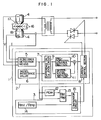
- Fig. 1 is a diagram showing a general configuration of a resistance welding control system useful for performing the method according to a first embodiment of the present invention.
- Fig. 2 is a graph showing a behavior of the detection resistance value.
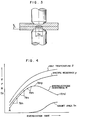
- Fig. 3 is a sectional view of a joint.
- Fig. 4 is a graph showing a behavior of the interelectrode resistance.
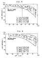
- Fig. 5 is a diagram showing the result of an experiment on the joint efficiency with Rel/Rep calculated and energization stopped.
- Fig. 6 shows the result of an experiment of the joint efficiency with the energization stopped by a resistance drop value ⁇ R.
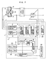
- Fig. 7 is a diagram showing a general configuration of a system useful for performing the method according to the second embodiment of the invention.
- Fig. 8 is a characteristic diagram showing the condition of the detection resistance value and the welding current.
- Fig. 9 is a characteristic diagram showing a proper ideal resistance value and a standard resistance value associated with a fault.
- Fig. 10 is a characteristic diagram showing the condition in which the initial values of the resistance values in Fig. 9 are rendered to coincide with each other.
- Fig. 11 is a characteristic diagram showing the condition in which the initial values of the resistance value associated with a fault in Fig. 9 is rendered to coincide with M3.
- Fig. 12 is a characteristic diagram showing an ideal resistance value.
- Fig. 13 is a graph showing a behavior of the interelectrode resistance for explaining the prior art.
- Fig. 1 is a diagram showing a general configuration of a resistance welding control system 1 for controlling the spot welding process
- Fig. 2 a graph showing the behavior of a detection resistance value.
- the resistance welding control system 1 (hereinafter called “the control system”) according to this embodiment comprises a resistance pattern tracking control section 2 for detecting an interelectrode resistance R in welding operation at each energization cycle (1/60 second) and causing a detection resistance value Re to follow a predetermined curve of a model or ideal resistance value Rm (described later), and an energization control section 3 for determining a de-energization time in order to control the energization time.
- One energization cycle period as selected, for example, 1/60 sec when the welding current is an AC current of 60 Hz.
- the one cycle period is not limited to this value, but may be any selected value.
- the resistance pattern tracking control section 2 includes resistance detection means 5 for detecting an interelectrode resistance R by measuring a voltage V applied between electrodes 4 and a welding current I, an ideal resistance value memory section or ideal resistance value storing means 6 for storing a predetermined ideal resistance value Rm, a compensation means or compensation control section 7 for determining a compensation amount of the welding current I, and a current control section 8 for controlling the welding current I in accordance with the compensation amount thus determined.
- the compensation control section 7 includes a difference calculation circuit 9 for calculating the difference between the resistance value Re detected by the resistance detection means 5 and the ideal resistance value Rm for each cycle, a proportional control section 10 for calculating a compensation amount in accordance with the difference determined by the difference calculation circuit 9 and a differential control section 11.
- the energization control section 3 includes a peak hold section 12 for storing a peak value Rep of the detection resistance value Re, an Rel/Rep calculation circuit 13 for calculating the value Rel/Rep for each cycle based on the peak value Rep and a detection resistance value Rel detected after appearance of the peak value Rep, an Rml/Rmp memory section 14 for storing a first proper value Rml/Rmp (described later) set in advance, and a comparator circuit 15 for comparing the value Rel/Rep determined by the Rel/Rep calculation circuit 13 with the proper value Rml/Rmp and applying a de-energization signal to the current control section 8 for de-energizing the operation when Rel/Rep reaches Rml/Rmp.
- a peak hold section 12 for storing a peak value Rep of the detection resistance value Re
- an Rel/Rep calculation circuit 13 for calculating the value Rel/Rep for each cycle based on the peak value Rep and a detection resistance value Rel detected after appearance of
- the nugget area Sn increases and the interelectrode resistance R gradually decreases from the peak value Rmp.
- the behavior of the interelectrode resistance R takes a waveform as shown in Fig. 4 with the temperature increase of the joint 17.
- the initial rise portion from a base interelectrode resistance A at the first cycle to the peak value Rmp is used as a model pattern or ideal pattern, which is determined based on the behavior of the interelectrode resistance R producing a sound joint condition shown in Fig. 4.
- Such an interelectrode resistance value is set at every cycle of the ideal pattern as an ideal resistance value Rm.
- Fig. 3 is a sectional view of the joint 17, and Fig. 4 a graph showing the behavior of the interelectrode resistance R with time.
- the heat input may become excessively large or small, resulting in generating a welding spark or causing a shortage of strength.
- a proper value of Rml/Rmp is set in advance on the basis of a waveform of the interelectrode resistance R involving a sound joint condition, and this value Rml/Rmp is stored in a memory 14, where Rmp designates a peak value of the interelectrode resistance R and Rml an interelectrode resistance at the time of de-energization.
- the peak value Rep of the interelectrode resistance R during welding is measured.
- the Rel/Rep value is calculated at every cycle, and when the value of Rel/Rep reaches Rml/Rmp, energization is stopped.
- the resistance value measured at this time point is designated as Rel.
- the de-energization is determined based on the calculation of the value of Rel/Rep this way, and therefore, in the case where the heat input is excessively large as mentioned above, the energization is stopped earlier (with a small ⁇ R) and in the case where the heat input is excessively small, the energization is stopped later (with a larger ⁇ R) than the case where the energization is stopped when the resistance drop ⁇ R reaches a predetermined value.
- Figs. 5 and 6 show results of experiments conducted in which the tensile shearing strength at the welded part is represented by the joint efficiency.
- the value (Rep - Rel)/Rep x 100 is set to 63%.
- an interelectrode resistance R is detected by measuring the welding current I and the voltage V applied between the electrodes 4 by resistance detection means 5.
- the difference between the detection resistance value Re and a predetermined ideal resistance value Rm stored in the ideal resistance value memory 6 is calculated at each cycle.
- a compensation amount is calculated by the proportional control section 10 and the differential control section 11 in accordance with the difference determined by the difference calculation circuit 9.
- the current control section 8 adjusts the welding current I on the basis of the compensation amount, thus optimizing the temperature increase of the joint 17.
- the initial behavior of the interelectrode resistance R under welding operation is thus caused to follow the predetermined ideal or model pattern.
- the energization control section 3 is operated to stop the energization appropriately.
- the peak value Rep of the detection resistance value Re is stored by a peak hold section 12, after which the Rel/Rep calculation circuit 13 determines the value of Rel/Rep from the peak value Rep and a resistance value Rel detected subsequently to the detection of the peak value Rep.
- the value Rel/Rep thus calculated is compared with the value Rml/Rmp stored in the Rml/Rmp memory 14 at the comparator circuit 15, and when Rel/Rep reaches Rml/Rmp, a de-energization signal for stopping energization is applied to the current control section 8.
- the current control section 8 receives this de-energization signal to stop the energization, thereby completing the control process.
- the aforementioned control operation stabilizes the temperature rise of the joint 17 and secure the proper nugget area, thus providing a sound welding quality in a stable manner.
- preheat means 20 supplies current of 1000 to 1500 (A) during 5 to 10 cycles as shown in Fig. 8 in the case where the thickness of the base metal 16 is 1 mm.
- a portion between the base metals 16 is heated for stable contact resistance.
- the interelectrode resistance R is detected by the resistance detection means 5.
- a cooling time is provided to stop the energization during the period from preheating to the resistance detection by the resistance detection means 5.
- This cooling time is provided for preventing the base metals 16 which may be circular in section with a small contact area therebetween from being increased too much in temperature by an excessive current flow during the preheating.
- the initial resistance pattern between the electrodes 4 for proper welding conditions is controlled to follow an ideal pattern M1 to M7 by current control, as shown in Fig. 9.
- the interelectrode resistance R at the first cycle may be increased as shown by D1 in Fig. 9.
- the pattern D1 to D7 is shown as a typical standard obtained when a predetermined current is supplied without any current control unlike in the first embodiment.
- the current is controlled as in the first embodiment, by contrast, it causes the interelectrode resistance R to follow the ideal pattern M1 to M7 with its starting point M1 coinciding with D1 as shown in Fig. 10, resulting in a substantial difference between the pattern D1 to D7 and the ideal pattern M1 to M7, which in turn causes the current to be increased considerably. With the increase in current, the heat quantity is also increased and the resultant overheating (or a welding spark) would reduce the strength.
- the resistance D1 measured at the first cycle is compared with the absolute or ideal value M1 of the predetermined model of ideal resistance value at the first cycle, and select an ideal starting point in a manner mentioned below.
- the resistance value D1 measured at the first cycle is rendered to coincide with the ideal resistance value M3 at the third cycle.
- the control is carried out so that the measured resistance values D1 to D5 substantially coincide with the ideal values M3 to M7 of the model or ideal pattern, thereby eliminating the problems of overheating, etc.
- the difference between the detection resistance value and the ideal resistance value is calculated by a difference calculation circuit 9 as in the first embodiment.
- an upper limit ideal value Mh and a lower limit ideal value Ml are set with ⁇ 5% allowances from an optimum ideal value M. (See Fig. 12)
- the welding current I is reduced according to Table 1 below.
- Table 1 R D Current reduction 1 to 10 ( ⁇ ) 5.0% down 11 to 20 ( ⁇ ) 7.5% down 21 to 40 ( ⁇ ) 10.0% down 41 ( ⁇ ) or more 12.5% down
- the welding current I is increased according to Table 2 below.
- Table 2 R D Current reduction 1 to 10 ( ⁇ ) 2.5% down 11 to 20 ( ⁇ ) 5.0% down 21 to 40 ( ⁇ ) 7.5% down Current is controlled in different amounts in Tables 1 and 2 above by reason of the fact that an overheat (or welding spatter) forms a serious welding defect in the resistance welding process.
- the amount of current increase therefore, is limited in such a manner as to prevent a sharp temperature increase, while the amount of current reduction is increased due to a low thermal response of the weld zone thereby to prevent an overheated condition (or welding spatter).
- the energization time tends to lengthen. Nevertheless, this poses no problem as experiments show that a satisfactory result is obtained if the energization time is 10 to 25 cycles for the metal thickness of about 1.2 mm.
- the welding current I is controlled in such a way that the detection resistance takes a value between the upper limit ideal value Mh and the lower limit ideal value Ml.
- the peak hold section 12 detects a peak value Rep of the detection resistance value, followed by the difference Rea between the value Rep and the detection resistance value Res at the first cycle shown in Fig. 8.
- the Rec/Rea calculation circuit 24 fetches the value Rec which is the peak value Rep less a predetermined value at each cycle thereby to calculate the value Rec/Rea at each cycle.
- the Rmc/Rma memory section 25 stores a first proper value Rmc/Rma according to an ideal pattern shown in Fig. 2, where Rma is the difference between the initial value Rms and the peak value Rmp, and Rmc the difference between the peak value Rmp and the interelectrode resistance value Rml with energization stopped.
- the second embodiment is such that relative values (differences Rea and Rec) are calculated to stop energization, so that even if the thickness of the base metal 16 undergoes a small variation leading to a changing detection resistance value, the energization is always accurately stopped, thereby producing a satisfactory joint condition.
- the resistance value is detected at each cycle, and therefore, even if energization is stopped when the calculated value Rec/Rea reaches the first proper value Rmc/Rma, a sharp power reduction (in two to four cycles) may form excessive nuggets before complete de-energization, often causing an overheat (or welding spark) due to the surface conditions of the base metal 16 or the pressure tracking ability or other disturbances.
- a predetermined second proper value Rmb/Rma is stored in the memory section 26, and when the value Rec/Rea reaches the second proper value Rmb/Rma as shown in Fig. 8, the welding current I is limited by a predetermined amount to realize a moderate resistance drop as shown by solid line. As a consequence, a sharp resistance drop is prevented.
- the number of energization cycles is detected by an energization cycle detector 22 in response to a signal from the peak hold section 12, and in accordance with the number of cycles before detection of a peak value Rep, the welding current I is controlled in the manner shown in Table 3 below.
- Table 3 Number of energization cycles Welding current 2 to 4 15% down 5 to 8 10% down 9 or more cycles 5% down
- the energization cycle detector 22 detects the number of cycles, and if this number is more than a predetermined number (say, 30 cycles) before an energization stop, a fault is indicated. This is due to the fact that with the increase in energization cycles, the electrodes 4 would be embedded in the base metals 16 under pressure, with the result that the strength between the base metals 16 is decreased.
- energization is stopped when the ratio Rel/Rep calculated reaches a predetermined value. Unless the behavior of the interelectrode resistance R in the welding operation deviates extremely from a model or ideal pattern, however, the energization may be stopped with the resistance drop ⁇ R as in the prior art with the same effect.
- the welding current I is limited when the calculated ratio Rec/Rea reaches the second proper value Rmb/Rma. Instead, the welding current I may be reduced by a predetermined value of resistance drop.
- an energization time from energization start to energization stop or the time length from a peak value Rep to an energization stop may be set.
- a displacement value of the electrodes 4 which is said to have a correlationship with the nugget formation, the value of change in transmission of ultrasonic wave or the value of change in acoustic emission may be set appropriately in advance, and the energization may be stopped in accordance with the set value.
- the current control section 8 employs a thyristor control by an AC waveform. It is, however, of course possible to realize the same effect by a DC waveform using a DC power supply or by transistor control. In such a case, a predetermined time sufficiently short to assure the controllability is secured as a cycle of interelectrode resistance detection.
- the resistance welding control system 1 for controlling the spot welding process, it may be applied with equal effect to the projection welding, butt welding or other resistance welding processes as well.
Landscapes
- Engineering & Computer Science (AREA)
- Mechanical Engineering (AREA)
- Resistance Welding (AREA)
- Arc Welding Control (AREA)
Claims (14)
- Méthode de réglage d'un dispositif de soudage par résistance,
dans laquelle des électrodes (4) sont appliquées sur les faces opposées d'un matériau à souder en vue du soudage, et lorsque le soudage du matériau est terminé pendant la période en cours, les électrodes (4) sont appliquées sur les faces opposées d'un autre matériau à souder la fois suivante, comprenant les étapes qui suivent:
stocker une valeur de résistance idéale prédéterminée par un moyen de stockage de valeur de résistance idéale (6),
détecter une résistance inter-électrodes à partir d'une tension et d'un courant entre les électrodes (4) pendant chaque cycle de la période de soudage de l'opération de soudage en cours par un moyen de détection de résistance (5),
comparer chacune des valeurs de résistance inter-électrodes détectées avec ladite valeur de résistance idéale prédéterminée par un moyen de compensation (7) et déterminer une valeur de compensation,
régler un courant de soudage (I) en accord avec la valeur de compensation,
ladite méthode étant caractérisée par les étapes suivantes:
stocker un rapport Rm1/Rmp par un moyen de mise en mémoire de Rm1/Rmp, où Rmp est une valeur de pic et Rm1 est une valeur de la résistance inter-électrodes (R) au moment de la désexcitation qui est inférieure d'une quantité prédéterminée à la valeur de pic Rmp basée sur la forme d'onde de la résistance inter-électrodes (R) impliquant une condition de joint sûre, et
l'arrêt du courant de soudage (I) quand un rapport Rel/Rep atteint ledit rapport stocké Rm1/Rmp, où Rep est une valeur de pic et
Rel une valeur de résistance de détection inférieure à Rep - Méthode selon la revendication 1, caractérisée en ce que ledit moyen de compensation (7) fonctionne de manière qu'un premier taux, auquel le courant de soudage (I) est réduit quand la valeur de résistance de détection est supérieure à la valeur de résistance idéale, soit supérieur à un second taux pour lequel le courant de soudage (I) est augmenté quand la valeur de résistance de détection est inférieure à la valeur de résistance idéale.
- Méthode selon la revendication 1, caractérisée en ce qu'elle comprend l'étape de la détection de la valeur substantielle de pic Rep de la valeur de résistance de détection par un moyen de blocage de pic (12), qui est inclus dans un moyen de commande d'excitation (3).
- Méthode selon la revendication 3, caractérisée en ce que le rapport Rm1/Rmp est stocké dans ledit moyen à mémoire de Rm1/Rmp (14) qui est inclus dans ledit moyen de commande d'excitation (3).
- Méthode selon la revendication 1, caractérisée en ce qu'elle comprend l'étape consistant à utiliser un courant alternatif dont le sens du courant est inversé pendant des cycles prédéterminés d'une seconde.
- Méthode selon la revendication 1, caractérisée en ce qu'elle comprend l'étape constant en le préchauffage des métaux de base (16) par un moyen de préchauffage (20), un courant prédéterminé étant appliqué entre les électrodes (4) pour chauffer les métaux de base (16) et stabiliser la résistance inter-électrodes (R) avant la détection de la résistance inter-électrodes (R).
- Méthode selon la revendication 1, caractérisée en ce qu'elle comprend l'étape consistant à changer la valeur de résistance idéale du moyen de compensation (7) par un moyen (2) en réponse à l'amplitude de la résistance inter-électrodes (R) détectée au cours d'un premier cycle par un moyen de détection de résistance (5).
- Méthode pour régler un dispositif de soudage par résistance,
dans laquelle des électrodes (4) sont appliquées sur les faces opposées d'un matériau à souder en vue du soudage, et lorsque le soudage du matériau est terminé pendant la période en cours, les électrodes (4) sont appliquées sur les faces opposées d'un autre matériau à souder la fois suivante, comprenant les étapes qui suivent:
stocker une valeur de résistance idéale prédéterminée par un moyen de stockage de valeur de résistance idéale (6),
détecter une résistance inter-électrodes à partir d'une tension et d'un courant entre les électrodes (4) pendant chaque cycle de la période de soudage de l'opération de soudage en cours par un moyen de détection de résistance (5),
comparer chacune des valeurs de résistance inter-électrodes détectées avec ladite valeur de résistance idéale prédéterminée par un moyen de compensation (7) et déterminer une valeur de compensation,
régler un courant de soudage (I) en accord avec la valeur de compensation,
ladite méthode étant caractérisée par les étapes suivantes:
stocker une première valeur appropriée correspondant au rapport Rmc/Rma par un moyen de mise en mémoire de Rmc/Rma (25), où Rma représente une quantité entre une valeur initiale et une valeur de pic et Rmc est une quantité entre ladite valeur de pic et une valeur inférieure de la résistance inter-électrodes (R) au moment de la désexcitation, basée sur une forme d'onde de la résistance interélectrodes (R) associée à une condition de joint satisfaisante,
détecter la valeur initiale de la valeur de résistance de détection et la quantité Rea représentant une valeur substantielle de pic par un moyen de détection de pic (12),
calculer une valeur correspondant au rapport Rec/Rea par un moyen de calcul de Rec/Rea (24), où Rec est la différence entre la valeur de pic et Rea la valeur de résistance qui est détectée pour chaque cycle, et
arrêter l'excitation par ledit moyen de commande d'excitation (3) quand le rapport calculé Rec/Rea atteint la première valeur appropriée Rmc/Rma. - Méthode selon la revendication 5, caractérisée en ce que ledit moyen de commande d'excitation (3) réduit le courant de soudage (1) d'une quantité prédéterminée quand la valeur de résistance de détection diminue d'une première quantité prédéterminée à partir de la valeur substantielle de pic de la valeur de résistance de détection et arrête l'alimentation du courant de soudage (I) quand la valeur de résistance de détection diminue d'une seconde quantité prédéterminée supérieure à la première quantité prédéterminée.
- Méthode selon la revendication 9, caractérisée en ce qu'un moyen de détection de nombre de cycles (22) est prévu pour détecter le nombre de cycles avant que la valeur de résistance de détection atteigne une valeur de pic, le courant de soudage (I) étant réduit d'une quantité progressivement supérieure à la diminution du nombre de cycles.
- Méthode selon la revendication 5, caractérisée en ce qu'une alarme est émise quand le nombre de cycles entre le premier cycle et un cycle associé à l'arrêt de l'excitation est supérieur à une valeur prédéterminée.
- Méthode selon la revendication 5, caractérisée en ce que ladite valeur de résistance idéale comprend une limite supérieure idéale (Mh) et une limite inférieure idéale (M ) avec une marge prédéterminée à partir d'une valeur de résistance idéale appropriée entre elles, ledit moyen de compensation (7) étant tel que le taux auquel le courant de soudage (I) est réduit quand la valeur de résistance de détection est supérieure à ladite limite supérieure idéale (Mh) est supérieur au taux auquel le courant de soudage (I) est augmenté quand ladite valeur de résistance de détection est inférieure à ladite limite inférieure idéale (M ), lesdits taux étant progressivement supérieurs à l'augmentation de la différence entre la valeur de résistance de détection et celle de la limite inférieure idéale (M ) ou de la limite supérieure idéale (Mh) qui a été sélectionnée.
- Méthode selon la revendication 6, caractérisée en ce qu'un moyen est prévu pour refroidir ledit moyen de préchauffage (20) pendant une période prédéterminée après son chauffage.
- Méthode selon la revendication 7, caractérisée en ce que ledit moyen (2) comprend un moyen pour détecter un cycle pendant lequel une valeur de résistance idéale a été modifiée pour parvenir approximativement à la valeur de résistance détectée au cours du premier cycle par le moyen de détection de résistance (5) et pour modifier la valeur de résistance détectée au cours du premier cycle pour qu'elle soit sensiblement en accord avec la valeur de résistance idéale pendant le cycle détecté.
Applications Claiming Priority (2)
| Application Number | Priority Date | Filing Date | Title |
|---|---|---|---|
| JP16854588 | 1988-07-06 | ||
| JP168545/88 | 1988-07-06 |
Publications (2)
| Publication Number | Publication Date |
|---|---|
| EP0350013A1 EP0350013A1 (fr) | 1990-01-10 |
| EP0350013B1 true EP0350013B1 (fr) | 1993-09-15 |
Family
ID=15870003
Family Applications (1)
| Application Number | Title | Priority Date | Filing Date |
|---|---|---|---|
| EP89112290A Expired - Lifetime EP0350013B1 (fr) | 1988-07-06 | 1989-07-05 | Méthode de réglage pour le soudage par résistance |
Country Status (4)
| Country | Link |
|---|---|
| US (1) | US4963707A (fr) |
| EP (1) | EP0350013B1 (fr) |
| JP (1) | JPH0815669B2 (fr) |
| DE (1) | DE68909127T2 (fr) |
Families Citing this family (48)
| Publication number | Priority date | Publication date | Assignee | Title |
|---|---|---|---|---|
| ES2091456T3 (es) * | 1990-12-13 | 1996-11-01 | Siemens Ag | Procedimiento y dispositivo para la verificacion de la calidad de uniones de soldadura por puntos. |
| US5399827A (en) * | 1990-12-13 | 1995-03-21 | Siemens Aktiengesellschaft | Method and device for determining the temperature at a spot-welded joint and a method for assessing the quality of a spot-welded joint |
| JP3314407B2 (ja) * | 1992-01-28 | 2002-08-12 | 株式会社デンソー | 被膜導電部材の抵抗溶接制御方法及びその装置 |
| JPH0759351B2 (ja) * | 1992-06-10 | 1995-06-28 | 株式会社ナ・デックス | 溶接コントローラ |
| FR2694899B1 (fr) * | 1992-08-19 | 1994-09-23 | Paul Leon | Procédé de mesure d'une grandeur représentative d'une caractéristique physique et/ou mécanique d'une soudure par points, applications de ce procédé au soudage par points. |
| US5484976A (en) * | 1993-10-01 | 1996-01-16 | Axis Usa, Inc. | Fusing methods and apparatus for use in making dynamo-electric machines |
| JP2783155B2 (ja) * | 1994-04-20 | 1998-08-06 | 株式会社デンソー | 抵抗溶接用制御方法及び装置 |
| US6359249B1 (en) | 1995-04-19 | 2002-03-19 | Dct, Inc. | No wat welding system |
| JP3161339B2 (ja) * | 1996-09-24 | 2001-04-25 | 松下電器産業株式会社 | 抵抗溶接機の溶接条件制御方法 |
| AUPO607397A0 (en) * | 1997-04-08 | 1997-05-01 | University Of Sydney, The | Weld quality measurement |
| JP3221356B2 (ja) * | 1997-05-14 | 2001-10-22 | 松下電器産業株式会社 | 抵抗溶接部の品質評価方法および装置 |
| US5889262A (en) * | 1997-05-15 | 1999-03-30 | Seah Steel Corporation | System for and method of automatically controlling amount of input heat in high-frequency electric resistance welding machine |
| JP3540125B2 (ja) | 1997-06-12 | 2004-07-07 | 矢崎総業株式会社 | 抵抗溶接の品質検査方法 |
| JP3886603B2 (ja) * | 1997-07-14 | 2007-02-28 | 株式会社ナ・デックス | 単位体積当たりの累積発熱量を指標とする抵抗溶接システム |
| US6573470B1 (en) | 1998-08-05 | 2003-06-03 | Dct, Inc. | Weld gun heat removal |
| AU3341900A (en) * | 1998-08-05 | 2000-12-18 | Dct, Inc. | Welding system |
| WO2001036141A1 (fr) | 1999-11-19 | 2001-05-25 | Dct, Inc. | Pistolet de soudage a bras multiples |
| FR2803785B1 (fr) * | 2000-01-18 | 2002-04-12 | Peugeot Citroen Automobiles Sa | Procede de supervision d'un processus de soudage par resistance |
| JP3220125B1 (ja) | 2000-04-28 | 2001-10-22 | 剛氏有限公司 | 紐状の毛皮又は毛皮状素材を使用した生地並びにこれを使用した製品 |
| TW471987B (en) * | 2000-12-04 | 2002-01-11 | Essor Internat Inc | Spot welding quality monitoring device and its method |
| US9220576B2 (en) | 2003-08-07 | 2015-12-29 | Ivoclar Vivadent Ag | Machining of ceramic materials |
| US8444756B2 (en) | 2003-08-07 | 2013-05-21 | Ivoclar Vivadent Ag | Lithium silicate materials |
| ES2489523T3 (es) | 2005-02-08 | 2014-09-02 | Ivoclar Vivadent Ag | Material vitrocerámico de silicato de litio |
| DE102006038786A1 (de) * | 2006-08-18 | 2008-02-21 | Robert Bosch Gmbh | Steuerung einer Schweißvorrichtung |
| DE102006060197A1 (de) * | 2006-12-18 | 2008-06-26 | MV Marketing und Vertriebs-GmbH & Co. KG Wieländer + Schill | Vorrichtung und Verfahren zum Widerstandsschweißen |
| JP5127788B2 (ja) | 2009-08-01 | 2013-01-23 | 株式会社豊田中央研究所 | 抵抗溶接方法、抵抗溶接部材、抵抗溶接機、抵抗溶接機の制御方法とその制御プログラムおよびその制御装置並びに抵抗溶接の評価方法とその評価プログラムおよびその評価装置 |
| US9306230B2 (en) * | 2009-11-19 | 2016-04-05 | GM Global Technology Operations LLC | Online estimation of cathode inlet and outlet RH from stack average HFR |
| US8357870B1 (en) | 2010-03-22 | 2013-01-22 | Honda Motor Co., Ltd. | Intelligent stepper welding system and method |
| US8865606B2 (en) | 2010-04-16 | 2014-10-21 | Ivoclar Vivadent Ag | Process for the preparation of dental restorations |
| ES2581452T3 (es) | 2010-04-16 | 2016-09-05 | Ivoclar Vivadent Ag | Vitrocerámica y vidrio de silicato de litio con óxido de metal de transición |
| JP6681659B2 (ja) | 2011-10-14 | 2020-04-15 | イフォクレール ヴィヴァデント アクチェンゲゼルシャフトIvoclar Vivadent AG | 二価の金属酸化物を含むケイ酸リチウムガラスセラミックおよびケイ酸リチウムガラス |
| KR20140077949A (ko) | 2011-10-14 | 2014-06-24 | 이보클라 비바덴트 아게 | 6가 금속 산화물을 포함하는 리튬 실리케이트 유리 세라믹 및 리튬 실리케이트 유리 |
| ES2563739T3 (es) | 2011-10-14 | 2016-03-16 | Ivoclar Vivadent Ag | Vitrocerámica y vidrio de silicato de litio con óxido metálico pentavalente |
| KR20140075777A (ko) | 2011-10-14 | 2014-06-19 | 이보클라 비바덴트 아게 | 3가 금속 산화물을 포함하는 리튬 실리케이트 유리 세라믹 및 리튬 실리케이트 유리 |
| PL2765977T3 (pl) | 2011-10-14 | 2016-06-30 | Ivoclar Vivadent Ag | Litowokrzemianowa ceramika szklana i szkło z tlenkiem jednowartościowego metalu |
| PL2765976T3 (pl) | 2011-10-14 | 2016-07-29 | Ivoclar Vivadent Ag | Litowokrzemianowa ceramika szklana i szkło zawierające tlenek metalu czterowartościowego |
| JP5977442B2 (ja) | 2012-05-04 | 2016-08-24 | イフォクレール ヴィヴァデント アクチェンゲゼルシャフトIvoclar Vivadent AG | 二ケイ酸リチウムアパタイトガラスセラミック |
| IN2014DN09498A (fr) | 2012-05-11 | 2015-07-17 | Ivoclar Vivadent Ag | |
| RU2612707C2 (ru) | 2012-05-11 | 2017-03-13 | Ивоклар Вивадент Аг | Предварительно спеченная заготовка для зубов |
| EP2765119B1 (fr) | 2013-02-12 | 2021-07-28 | Ivoclar Vivadent AG | Ébauche à des fins dentaires |
| EP2792649B1 (fr) | 2013-04-15 | 2019-11-27 | Ivoclar Vivadent AG | Vitrocéramique et verre au lithium-silice ayant une teneur en oxyde de rubidium |
| FR3016818B1 (fr) * | 2014-01-27 | 2016-08-19 | Gys | Methode de soudage avec determination des parametres de soudage par le calcul d'une impedance cible, et dispositif de mise en œuvre du procede |
| EP2944619B1 (fr) | 2014-05-13 | 2023-08-09 | Ivoclar Vivadent AG | Procédé de fabrication de verres en silicate de lithium et vitrocéramique en silicate de lithium |
| CN105397259B (zh) * | 2014-08-04 | 2017-10-03 | 合肥国声电子通信有限责任公司 | 一种手工中频焊接控制柜中焊接控制器控制方法 |
| EP3050856B1 (fr) | 2015-01-30 | 2019-05-29 | Ivoclar Vivadent AG | Vitrocéramique en diopside-lithium-silice |
| JP6572281B2 (ja) * | 2017-10-06 | 2019-09-04 | ファナック株式会社 | スポット溶接システム |
| JP2020171942A (ja) * | 2019-04-11 | 2020-10-22 | トヨタ自動車株式会社 | 抵抗スポット溶接装置 |
| CN120962077A (zh) * | 2025-10-21 | 2025-11-18 | 南通维益机电有限公司 | 一种金属材料焊接用的机床焊接方法及系统 |
Family Cites Families (10)
| Publication number | Priority date | Publication date | Assignee | Title |
|---|---|---|---|---|
| US4302653A (en) * | 1980-04-02 | 1981-11-24 | Weltronic Company | Method and apparatus for monitoring and controlling a resistance welding operation |
| JPS571582A (en) * | 1980-06-02 | 1982-01-06 | Nissan Motor Co Ltd | Method for assessing quality of weld zone in resistance welding |
| JPS602154B2 (ja) * | 1980-12-27 | 1985-01-19 | 宮地電子株式会社 | 抵抗溶接制御方法 |
| JPS57202988A (en) * | 1981-06-10 | 1982-12-13 | Nippon Abionikusu Kk | Accommodation controlling device for resistance welding |
| JPS6040957B2 (ja) * | 1981-08-06 | 1985-09-13 | 宮地電子株式会社 | 抵抗溶接の品質の制御方法 |
| JPS5865583A (ja) * | 1981-10-15 | 1983-04-19 | Nippon Abionikusu Kk | 抵抗溶接装置 |
| JPS58181488A (ja) * | 1982-04-16 | 1983-10-24 | Sanyo Kiko Kk | 抵抗溶接電流制御方法 |
| JPS6178580A (ja) * | 1984-09-21 | 1986-04-22 | Dengensha Mfg Co Ltd | 抵抗溶接用制御方法 |
| IT1179830B (it) * | 1984-11-26 | 1987-09-16 | Fiat Auto Spa | Dispositivo di controllo per apparecchiature per saldatura elettrica a resistenza particolarmente per il controllo di apparecchiature per la saldatura di parti di carrozzerie di autoveicoli |
| US4675494A (en) * | 1985-11-18 | 1987-06-23 | Ford Motor Company | Preheat time compensating weld control |
-
1989
- 1989-06-30 JP JP1170683A patent/JPH0815669B2/ja not_active Expired - Fee Related
- 1989-07-05 US US07/375,778 patent/US4963707A/en not_active Expired - Lifetime
- 1989-07-05 EP EP89112290A patent/EP0350013B1/fr not_active Expired - Lifetime
- 1989-07-05 DE DE89112290T patent/DE68909127T2/de not_active Expired - Fee Related
Also Published As
| Publication number | Publication date |
|---|---|
| US4963707A (en) | 1990-10-16 |
| DE68909127D1 (de) | 1993-10-21 |
| JPH0815669B2 (ja) | 1996-02-21 |
| EP0350013A1 (fr) | 1990-01-10 |
| DE68909127T2 (de) | 1994-02-10 |
| JPH038585A (ja) | 1991-01-16 |
Similar Documents
| Publication | Publication Date | Title |
|---|---|---|
| EP0350013A1 (fr) | Méthode de réglage pour le soudage par résistance | |
| US4329561A (en) | Method of ensuring the maintenance of constant quality of spot welds | |
| US5892197A (en) | Control apparatus for resistance welding machine | |
| US4456810A (en) | Adaptive schedule selective weld control | |
| EP0080514A1 (fr) | Procede et dispositif de commande du soudage par resistance | |
| US6051807A (en) | Pulse arc welding apparatus | |
| JPS59206163A (ja) | ア−ク溶接機のア−ク長制御装置 | |
| US4442337A (en) | Method and system for dual control of resistance welding | |
| US4408114A (en) | Resistance welding with pressure control in response to deviation between welding voltage and time varying reference values therefor | |
| JPH0994673A (ja) | 抵抗溶接の制御装置および制御方法 | |
| US4302656A (en) | Controlling the operations of an electric arc welder | |
| JPS6264483A (ja) | 溶接電流の調整方法および装置 | |
| US4384187A (en) | Feedback control system for pulsed DC arc welding | |
| KR880002411B1 (ko) | 직류 펄스 변조 아아크 용접 제어 장치 및 방법 | |
| JPH0759351B2 (ja) | 溶接コントローラ | |
| US4387289A (en) | Control system for resistance welding | |
| US5889262A (en) | System for and method of automatically controlling amount of input heat in high-frequency electric resistance welding machine | |
| JP2916872B2 (ja) | 溶接ワイヤ位置の制御方法及び装置 | |
| US4634828A (en) | Control method of resistance welding | |
| JP4151777B2 (ja) | ホットワイヤ溶接方法および装置 | |
| JPH0422584A (ja) | スポット溶接機の溶接電流制御方法及び装置 | |
| US5124521A (en) | Method and apparatus for controlling welding current in resistance welding | |
| JPS63180384A (ja) | チツプ間電力制御形抵抗溶接制御方式 | |
| JP3303527B2 (ja) | 溶接ワイヤ位置の検出方法及びその装置 | |
| EP0294485A1 (fr) | Dispositif de commande pour machines de soudage a l'arc automatiques |
Legal Events
| Date | Code | Title | Description |
|---|---|---|---|
| PUAI | Public reference made under article 153(3) epc to a published international application that has entered the european phase |
Free format text: ORIGINAL CODE: 0009012 |
|
| AK | Designated contracting states |
Kind code of ref document: A1 Designated state(s): DE FR GB |
|
| 17P | Request for examination filed |
Effective date: 19900625 |
|
| 17Q | First examination report despatched |
Effective date: 19910430 |
|
| GRAA | (expected) grant |
Free format text: ORIGINAL CODE: 0009210 |
|
| AK | Designated contracting states |
Kind code of ref document: B1 Designated state(s): DE FR GB |
|
| REF | Corresponds to: |
Ref document number: 68909127 Country of ref document: DE Date of ref document: 19931021 |
|
| ET | Fr: translation filed | ||
| PLBE | No opposition filed within time limit |
Free format text: ORIGINAL CODE: 0009261 |
|
| STAA | Information on the status of an ep patent application or granted ep patent |
Free format text: STATUS: NO OPPOSITION FILED WITHIN TIME LIMIT |
|
| 26N | No opposition filed | ||
| REG | Reference to a national code |
Ref country code: GB Ref legal event code: 746 Effective date: 19950612 |
|
| REG | Reference to a national code |
Ref country code: FR Ref legal event code: D6 |
|
| REG | Reference to a national code |
Ref country code: GB Ref legal event code: IF02 |
|
| PGFP | Annual fee paid to national office [announced via postgrant information from national office to epo] |
Ref country code: GB Payment date: 20050629 Year of fee payment: 17 |
|
| PGFP | Annual fee paid to national office [announced via postgrant information from national office to epo] |
Ref country code: DE Payment date: 20050630 Year of fee payment: 17 |
|
| PGFP | Annual fee paid to national office [announced via postgrant information from national office to epo] |
Ref country code: FR Payment date: 20050708 Year of fee payment: 17 |
|
| PG25 | Lapsed in a contracting state [announced via postgrant information from national office to epo] |
Ref country code: GB Free format text: LAPSE BECAUSE OF NON-PAYMENT OF DUE FEES Effective date: 20060705 |
|
| PG25 | Lapsed in a contracting state [announced via postgrant information from national office to epo] |
Ref country code: DE Free format text: LAPSE BECAUSE OF NON-PAYMENT OF DUE FEES Effective date: 20070201 |
|
| GBPC | Gb: european patent ceased through non-payment of renewal fee |
Effective date: 20060705 |
|
| REG | Reference to a national code |
Ref country code: FR Ref legal event code: ST Effective date: 20070330 |
|
| PG25 | Lapsed in a contracting state [announced via postgrant information from national office to epo] |
Ref country code: FR Free format text: LAPSE BECAUSE OF NON-PAYMENT OF DUE FEES Effective date: 20060731 |